EP2604805A2 - Statoraussenringanordnung für ein Gasturbinentriebwerk - Google Patents
Statoraussenringanordnung für ein Gasturbinentriebwerk Download PDFInfo
- Publication number
- EP2604805A2 EP2604805A2 EP12195953.0A EP12195953A EP2604805A2 EP 2604805 A2 EP2604805 A2 EP 2604805A2 EP 12195953 A EP12195953 A EP 12195953A EP 2604805 A2 EP2604805 A2 EP 2604805A2
- Authority
- EP
- European Patent Office
- Prior art keywords
- hanger
- wall
- aft
- shroud
- shroud segment
- Prior art date
- Legal status (The legal status is an assumption and is not a legal conclusion. Google has not performed a legal analysis and makes no representation as to the accuracy of the status listed.)
- Withdrawn
Links
- 239000000463 material Substances 0.000 claims abstract description 26
- 230000007704 transition Effects 0.000 claims description 8
- 239000002826 coolant Substances 0.000 claims description 7
- 230000001154 acute effect Effects 0.000 claims description 5
- 239000011248 coating agent Substances 0.000 claims description 5
- 238000000576 coating method Methods 0.000 claims description 5
- 239000007789 gas Substances 0.000 description 19
- 239000011153 ceramic matrix composite Substances 0.000 description 18
- 238000001816 cooling Methods 0.000 description 4
- 239000000919 ceramic Substances 0.000 description 3
- 238000010276 construction Methods 0.000 description 3
- 238000000034 method Methods 0.000 description 3
- 238000007789 sealing Methods 0.000 description 3
- 230000009471 action Effects 0.000 description 2
- 239000000567 combustion gas Substances 0.000 description 2
- 230000003247 decreasing effect Effects 0.000 description 2
- 239000000835 fiber Substances 0.000 description 2
- 230000037406 food intake Effects 0.000 description 2
- 229910052751 metal Inorganic materials 0.000 description 2
- 239000002184 metal Substances 0.000 description 2
- 229910001092 metal group alloy Inorganic materials 0.000 description 2
- 239000000203 mixture Substances 0.000 description 2
- 238000010926 purge Methods 0.000 description 2
- HBMJWWWQQXIZIP-UHFFFAOYSA-N silicon carbide Chemical compound [Si+]#[C-] HBMJWWWQQXIZIP-UHFFFAOYSA-N 0.000 description 2
- 238000011144 upstream manufacturing Methods 0.000 description 2
- PZNSFCLAULLKQX-UHFFFAOYSA-N Boron nitride Chemical compound N#B PZNSFCLAULLKQX-UHFFFAOYSA-N 0.000 description 1
- WOIHABYNKOEWFG-UHFFFAOYSA-N [Sr].[Ba] Chemical compound [Sr].[Ba] WOIHABYNKOEWFG-UHFFFAOYSA-N 0.000 description 1
- 229910000323 aluminium silicate Inorganic materials 0.000 description 1
- 230000004888 barrier function Effects 0.000 description 1
- 238000005452 bending Methods 0.000 description 1
- HNPSIPDUKPIQMN-UHFFFAOYSA-N dioxosilane;oxo(oxoalumanyloxy)alumane Chemical compound O=[Si]=O.O=[Al]O[Al]=O HNPSIPDUKPIQMN-UHFFFAOYSA-N 0.000 description 1
- 230000007613 environmental effect Effects 0.000 description 1
- 239000000284 extract Substances 0.000 description 1
- 239000000446 fuel Substances 0.000 description 1
- 230000006872 improvement Effects 0.000 description 1
- 230000013011 mating Effects 0.000 description 1
- 239000011159 matrix material Substances 0.000 description 1
- 239000007769 metal material Substances 0.000 description 1
- 150000002739 metals Chemical class 0.000 description 1
- 238000012986 modification Methods 0.000 description 1
- 230000004048 modification Effects 0.000 description 1
- 230000008569 process Effects 0.000 description 1
- 230000000717 retained effect Effects 0.000 description 1
- 229910010271 silicon carbide Inorganic materials 0.000 description 1
- 229910001233 yttria-stabilized zirconia Inorganic materials 0.000 description 1
Images


Classifications
-
- F—MECHANICAL ENGINEERING; LIGHTING; HEATING; WEAPONS; BLASTING
- F01—MACHINES OR ENGINES IN GENERAL; ENGINE PLANTS IN GENERAL; STEAM ENGINES
- F01D—NON-POSITIVE DISPLACEMENT MACHINES OR ENGINES, e.g. STEAM TURBINES
- F01D25/00—Component parts, details, or accessories, not provided for in, or of interest apart from, other groups
- F01D25/24—Casings; Casing parts, e.g. diaphragms, casing fastenings
- F01D25/246—Fastening of diaphragms or stator-rings
-
- F—MECHANICAL ENGINEERING; LIGHTING; HEATING; WEAPONS; BLASTING
- F01—MACHINES OR ENGINES IN GENERAL; ENGINE PLANTS IN GENERAL; STEAM ENGINES
- F01D—NON-POSITIVE DISPLACEMENT MACHINES OR ENGINES, e.g. STEAM TURBINES
- F01D11/00—Preventing or minimising internal leakage of working-fluid, e.g. between stages
- F01D11/08—Preventing or minimising internal leakage of working-fluid, e.g. between stages for sealing space between rotor blade tips and stator
- F01D11/12—Preventing or minimising internal leakage of working-fluid, e.g. between stages for sealing space between rotor blade tips and stator using a rubstrip, e.g. erodible. deformable or resiliently-biased part
-
- F—MECHANICAL ENGINEERING; LIGHTING; HEATING; WEAPONS; BLASTING
- F01—MACHINES OR ENGINES IN GENERAL; ENGINE PLANTS IN GENERAL; STEAM ENGINES
- F01D—NON-POSITIVE DISPLACEMENT MACHINES OR ENGINES, e.g. STEAM TURBINES
- F01D11/00—Preventing or minimising internal leakage of working-fluid, e.g. between stages
- F01D11/08—Preventing or minimising internal leakage of working-fluid, e.g. between stages for sealing space between rotor blade tips and stator
- F01D11/14—Adjusting or regulating tip-clearance, i.e. distance between rotor-blade tips and stator casing
- F01D11/20—Actively adjusting tip-clearance
- F01D11/24—Actively adjusting tip-clearance by selectively cooling-heating stator or rotor components
-
- F—MECHANICAL ENGINEERING; LIGHTING; HEATING; WEAPONS; BLASTING
- F01—MACHINES OR ENGINES IN GENERAL; ENGINE PLANTS IN GENERAL; STEAM ENGINES
- F01D—NON-POSITIVE DISPLACEMENT MACHINES OR ENGINES, e.g. STEAM TURBINES
- F01D5/00—Blades; Blade-carrying members; Heating, heat-insulating, cooling or antivibration means on the blades or the members
- F01D5/12—Blades
- F01D5/28—Selecting particular materials; Particular measures relating thereto; Measures against erosion or corrosion
- F01D5/284—Selection of ceramic materials
-
- F—MECHANICAL ENGINEERING; LIGHTING; HEATING; WEAPONS; BLASTING
- F05—INDEXING SCHEMES RELATING TO ENGINES OR PUMPS IN VARIOUS SUBCLASSES OF CLASSES F01-F04
- F05D—INDEXING SCHEME FOR ASPECTS RELATING TO NON-POSITIVE-DISPLACEMENT MACHINES OR ENGINES, GAS-TURBINES OR JET-PROPULSION PLANTS
- F05D2240/00—Components
- F05D2240/10—Stators
- F05D2240/11—Shroud seal segments
-
- F—MECHANICAL ENGINEERING; LIGHTING; HEATING; WEAPONS; BLASTING
- F05—INDEXING SCHEMES RELATING TO ENGINES OR PUMPS IN VARIOUS SUBCLASSES OF CLASSES F01-F04
- F05D—INDEXING SCHEME FOR ASPECTS RELATING TO NON-POSITIVE-DISPLACEMENT MACHINES OR ENGINES, GAS-TURBINES OR JET-PROPULSION PLANTS
- F05D2250/00—Geometry
- F05D2250/40—Movement of components
- F05D2250/41—Movement of components with one degree of freedom
-
- F—MECHANICAL ENGINEERING; LIGHTING; HEATING; WEAPONS; BLASTING
- F05—INDEXING SCHEMES RELATING TO ENGINES OR PUMPS IN VARIOUS SUBCLASSES OF CLASSES F01-F04
- F05D—INDEXING SCHEME FOR ASPECTS RELATING TO NON-POSITIVE-DISPLACEMENT MACHINES OR ENGINES, GAS-TURBINES OR JET-PROPULSION PLANTS
- F05D2260/00—Function
- F05D2260/30—Retaining components in desired mutual position
- F05D2260/38—Retaining components in desired mutual position by a spring, i.e. spring loaded or biased towards a certain position
-
- Y—GENERAL TAGGING OF NEW TECHNOLOGICAL DEVELOPMENTS; GENERAL TAGGING OF CROSS-SECTIONAL TECHNOLOGIES SPANNING OVER SEVERAL SECTIONS OF THE IPC; TECHNICAL SUBJECTS COVERED BY FORMER USPC CROSS-REFERENCE ART COLLECTIONS [XRACs] AND DIGESTS
- Y02—TECHNOLOGIES OR APPLICATIONS FOR MITIGATION OR ADAPTATION AGAINST CLIMATE CHANGE
- Y02T—CLIMATE CHANGE MITIGATION TECHNOLOGIES RELATED TO TRANSPORTATION
- Y02T50/00—Aeronautics or air transport
- Y02T50/60—Efficient propulsion technologies, e.g. for aircraft
Definitions
- This invention relates generally to gas turbine engines, and more particularly to apparatus and methods for mounting shrouds made of a low-ductility material in the turbine sections of such engines.
- a typical gas turbine engine includes a turbomachinery core having a high pressure compressor, a combustor, and a high pressure turbine in serial flow relationship.
- the core is operable in a known manner to generate a primary gas flow.
- the high pressure turbine also referred to as a gas generator turbine
- Each rotor comprises an annular array of blades or buckets carried by a rotating disk.
- the flowpath through the rotor is defined in part by a shroud, which is a stationary structure which circumscribes the tips of the blades or buckets.
- CMCs ceramic matrix composites
- CMC shrouds must be positively positioned within the engine in order to effectively perform.
- Some CMC shrouds have been designed with the shroud component attached to an engine case using a metallic clamping element. While effective for mounting and positioning, these designs can require multiple closely spaced bolts. High bending stress can occur in the bolts, which is contrary to best engineering practice for bolt use.
- CMC shroud mounting designs avoid the use of a bolted clamp, but transmit high loads from surrounding metallic hardware through the box cross-section of the CMC shroud itself. This reduces the reliability of the shroud segment.
- a shroud apparatus for a gas turbine engine includes: an annular metallic hanger; a shroud segment disposed inboard of the hanger, comprising low-ductility material and having a cross-sectional shape defined by opposed forward and aft walls, and opposed inner and outer walls, the walls extending between opposed first and second end faces, wherein the inner wall defines an arcuate inner flowpath surface; and a retainer mechanically coupled to the hanger which engages the shroud segment to retain the shroud segment to the hanger while permitting movement of the shroud segment in a radial direction.
- FIG. 1 depicts a small portion of a turbine, which is part of a gas turbine engine of a known type.
- the function of the turbine is to extract energy from high-temperature, pressurized combustion gases from an upstream combustor (not shown) and to convert the energy to mechanical work, in a known manner.
- the turbine drives an upstream compressor (not shown) through a shaft so as to supply pressurized air to the combustor.
- turbofan, turbojet and turboshaft engines as well as turbine engines used for other vehicles or in stationary applications.
- turbine shroud is used as an example, the principles of the present invention are applicable to any low-ductility flowpath component which is at least partially exposed to a primary combustion gas flowpath of a gas turbine engine.
- the turbine includes a stationary nozzle 10. It may be of unitary or built-up construction and includes a plurality of airfoil-shaped stationary turbine vanes 12 circumscribed by an annular outer band 14.
- the outer band 14 defines the outer radial boundary of the gas flow through the turbine nozzle 10. It may be a continuous annular element or it may be segmented.
- a shroud comprising a plurality of arcuate shroud segments 18 is arranged so as to encircle and closely surround the turbine blades 16 and thereby define the outer radial flowpath boundary for the hot gas stream flowing through the turbine blades 16.
- the outer band 21 defines the outer radial boundary of the gas flow through the turbine nozzle 17. It may be a continuous annular element or it may be segmented.
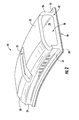
- each shroud segment 18 has a generally hollow cross-sectional shape defined by opposed inner and outer walls 20 and 22, and forward and aft walls 24 and 26. Radiused, sharp, or square-edged transitions may be used at the intersections of the walls.
- a shroud cavity 28 is defined within the walls 20, 22, 24, and 26.
- a transition wall 29 extends at an angle between the forward wall 24 and the outer wall 22, and lies at an acute angle to a central longitudinal axis of the engine when viewed in cross-section.
- An axially-elongated mounting slot 27 passes through the outer wall 22, the transition wall 29, and the forward wall 24.
- the inner wall 20 defines an arcuate radially inner flowpath surface 30.
- the inner wall 20 extends axially forward past the forward wall 24 to define a forward flange or overhang 32 and it also extends axially aft past the aft wall 26 to define an aft flange or overhang 34.
- the flowpath surface 30 follows a circular arc in elevation view (e.g. forward looking aft or vice-versa).
- the shroud segments 18 are constructed from a ceramic matrix composite (CMC) material of a known type.
- CMC materials include a ceramic type fiber for example SiC, forms of which are coated with a compliant material such as Boron Nitride (BN).
- BN Boron Nitride
- the fibers are carried in a ceramic type matrix, one form of which is Silicon Carbide (SiC).
- SiC Silicon Carbide
- CMC type materials have a room temperature tensile ductility of no greater than about 1%, herein used to define and mean a low tensile ductility material.
- CMC type materials have a room temperature tensile ductility in the range of about 0.4 to about 0.7%.
- shroud segments 18 could also be constructed from other low-ductility, high-temperature-capable materials.
- the flowpath surface 30 of the shroud segment 18 may incorporate a layer of environmental barrier coating ("EBC"), which may be an abradable material, and/or a rub-tolerant material of a known type suitable for use with CMC materials.
- EBC environmental barrier coating
- This layer is sometimes referred to as a "rub coat", designated at 38.
- the term "abradable” implies that the rub coat 38 is capable of being abraded, ground, or eroded away during contact with the tips of the turbine blades 16 as they turn inside the shroud segments 18 at high speed, with little or no resulting damage to the turbine blade tips.
- This abradable property may be a result of the material composition of the rub coat 38, by its physical configuration, or by some combination thereof.
- the rub coat 38 may comprise a ceramic layer, such as yttria stabilized zirconia or barium strontium aluminosilicate. Exemplary compositions and methods suitable for making the rub coat 38 are described in U.S. Pat. No. 7,749,565 (Johnson et al. ), which is incorporated herein by reference.
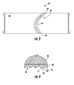
- FIGS. 3 and 4 depict the rub coat 38 in more detail.
- the rub coat 38 is patterned.
- the pattern enhances abradability of the rub coat by decreasing the surface area exposed to contact with the tips of the turbine blades 16.
- the rub coat 38 has a plurality of side-by-side grooves 39 formed therein.
- the presence of the grooves 39 gives the surface a shape comprising alternate peaks 41 and valleys 43.
- the grooves 39 run generally in a fore-to-aft direction, and each groove 39 has a forward end 45, a central portion 47, and an aft end 49,
- the grooves 39 may be curved.
- each groove 39 is curved such that its central portion 47 is offset in a lateral or tangential direction relative to its forward and aft ends 45 and 49.
- the shroud segments 18 include opposed end faces 42 (also commonly referred to as "slash" faces).
- the end faces 42 may lie in a plane parallel to the centerline axis of the engine, referred to as a "radial plane", or they may be slightly offset from the radial plane, or they may be oriented so that they are at an acute angle to such a radial plane.
- a radial plane When assembled into a complete ring, end gaps are present between the end faces 42 of adjacent shroud segments 18.
- One or more seals may be provided at the end faces 42. Similar seals are generally known as “spline seals" and take the form of thin strips of metal or other suitable material which are inserted in slots in the end faces 42. The spline seals span the gaps between shroud segments 18.
- the shroud segments 18 are mounted to a stationary metallic engine structure, shown in FIG. 1 .
- the stationary structure is part of a turbine case 44.
- the ring of shroud segments 18 is mounted to an array of arcuate shroud hangers 46 by way of an array of retainers 48 and bolts 50.
- each hanger 46 includes an annular body 52 which extends in a generally axial direction.
- the body 52 is angled such that its forward end is radially inboard of its aft end. It is penetrated at intervals by radially-aligned bolt holes 54.
- An annular forward outer leg 56 is disposed at the forward end of the body 52. It extends in a generally radial direction outboard of the body 52, and includes a forward hook 58 which extends axially aft.
- An annular aft outer leg 60 is disposed at the aft end of the body 52.
- the body 52 has one or more coolant feed passages 71 formed therein which serve to receive coolant from a source within the engine (such as compressor bleed air) and route the coolant to the inboard side of the body 52.
- the hangers 46 are installed into the turbine case 44 as follows.
- the forward hook 58 is received by an axially-forward facing forward rail 72 of the case 44.
- the aft hook 62 is received by an axially-forward facing aft rail 74 of the case 44.
- An anti-rotation pin 76 or other similar anti-rotation feature is received in the forward rail 72 and extends into a mating slot (not shown) in the forward hook 58.
- Each retainer 48 has a central portion 78 with two laterally-extending arms 80.
- the distal end of each arm 80 includes a concave-curved contact pad 82 which protrudes radially outward relative to the remainder of the arm 80.
- the central portion 78 is raised above the arms 80 in the radial direction and defines a clamping surface 84.
- a radially-aligned bore 86 extends through the central portion 78.
- a generally tubular insert 88 is swaged or otherwise secured to the bore 86 and includes a threaded fastener hole.
- the bore 86 could be threaded and the insert 88 eliminated.
- the retainer 48 is positioned in the shroud cavity 28 with the central portion 78 and the clamping surface 84 exposed through the mounting hole 27 in the outer wall 22.
- the retainer 48 is clamped against a boss 90 of the hanger 46 by the bolt 50 or other suitable fastener, and a spring 92 is clamped between the boss 90 and the clamping surface.
- Each spring 92 includes a center section with a mounting hole, and opposed laterally-extending arms 94.
- the relative dimensions of the boss 90, the retainer 48, and the shroud segment 18 are selected such that the retainers 48 limit the inboard movement of the shroud segments 18, but do not clamp the shroud segments 18 against the hanger 46 in the radial direction.
- the retainers 48 permit a definite clearance for movement in the radially outboard direction.
- the prevailing gas pressure load in the secondary flowpath urges the shroud segment 18 radially inboard against the retainer 48, while the retainer 48 deflects a small amount.
- the springs 92 function to hold the shroud segments 18 radially inboard against the retainers 48 during assembly and for an initial grinding process to circularize the ring of shroud segments 18.
- the springs 92 are sized such that they do not exert a substantial clamping load on the shroud segments 18.
- the aft inner leg 68 of the hanger 46 acts as a large cantilevered spring to counteract air pressure loads in operation. This spring action urges the forward wall 24 of the shroud segment 18 against the forward bearing surface 66 of the forward inner leg 64, resulting in a positive seal between the metallic hanger 46 and the CMC shroud segments, thereby decreasing cooling flow leakage.
- the forward and aft overhangs 32 and 34 are disposed in axially close proximity or in axially overlapping relationship with the components forward and aft of the shroud segment 18.
- the mounting slot 27 passes through the outer wall 22, the transition wall 29, and the forward wall 24.
- the shroud segments 18 thus incorporate a substantial amount of open area. There is not an air seal present between the perimeter of the mounting slot 27 and the hanger 46, and the shroud segments 18 do not, in and of themselves, function as plenums. Rather, the shroud segments 18 form a plenum in cooperation with the hangers 46, indicated generally at "P" in FIG. 1 .
- an annular sealing contact is present between the forward bearing surface 66 and the forward wall 24 of the shroud segment 18.
- an annular sealing contact is present between the aft bearing surface 70 and the aft wall 26 of the shroud segment 18.
- the sealing contact is ensured by the spring action of the aft inner leg 68 as described above.
- the shroud segments 18 may be considered to be the "inner portion" of the plenum and the hangers 46 may be considered to be the "outer portion” thereof.
- a hollow metallic impingement baffle 96 is disposed inside each shroud segment 18.
- the impingement baffle 96 fits closely to the retainer 48.
- the inboard wall of the impingement baffle has a number of impingement holes 98 formed therein, which direct coolant at the segment 18.
- the interior of the impingement baffle 96 communicates with the coolant feed passage 71 through a transfer passage 73 formed in the retainer 48.
- the shroud mounting apparatus described above is effective to mount a low-ductility shroud in a turbine engine without applying clamping loads directly thereto, and has several advantages compared to the prior art.
- the tapered edge (or wedge) shape on the forward side of the shroud allows the shroud mounting system to carry loads from forward of the shroud segments 18 to the turbine case 44 without transmitting directly through the shroud segments 18. By redirecting the load around the shroud segments 18, the stress in the shroud segments 18 remains relatively low.
- the overhangs 32 and 34 allow the shroud segments 18 to protect the supporting structure close to the flowpath while discouraging hot gas ingestion through the use of overlaps between the shroud segments 18 and the axially adjacent nozzles.
- This overlapping configuration requires less cooling flow to purge the shroud-to-nozzle cavities, thereby improving overall engine performance.
- the use of the overhangs 32 and 34 provides an overall turbine life improvement.
Landscapes
- Engineering & Computer Science (AREA)
- Mechanical Engineering (AREA)
- General Engineering & Computer Science (AREA)
- Turbine Rotor Nozzle Sealing (AREA)
Applications Claiming Priority (1)
| Application Number | Priority Date | Filing Date | Title |
|---|---|---|---|
| US13/327,349 US9726043B2 (en) | 2011-12-15 | 2011-12-15 | Mounting apparatus for low-ductility turbine shroud |
Publications (2)
| Publication Number | Publication Date |
|---|---|
| EP2604805A2 true EP2604805A2 (de) | 2013-06-19 |
| EP2604805A3 EP2604805A3 (de) | 2015-08-19 |
Family
ID=47297007
Family Applications (1)
| Application Number | Title | Priority Date | Filing Date |
|---|---|---|---|
| EP12195953.0A Withdrawn EP2604805A3 (de) | 2011-12-15 | 2012-12-06 | Statoraussenringanordnung für ein Gasturbinentriebwerk |
Country Status (5)
| Country | Link |
|---|---|
| US (1) | US9726043B2 (de) |
| EP (1) | EP2604805A3 (de) |
| JP (1) | JP2013124664A (de) |
| CN (1) | CN103161525B (de) |
| CA (1) | CA2798307A1 (de) |
Cited By (17)
| Publication number | Priority date | Publication date | Assignee | Title |
|---|---|---|---|---|
| EP3037628A1 (de) * | 2014-12-23 | 2016-06-29 | Rolls-Royce Corporation | Turbinenummantelung |
| FR3045717A1 (fr) * | 2015-12-22 | 2017-06-23 | Snecma | Dispositif de pilotage de jeu en sommets d'aubes rotatives de turbine |
| US9752592B2 (en) | 2013-01-29 | 2017-09-05 | Rolls-Royce Corporation | Turbine shroud |
| EP3228833A1 (de) * | 2016-04-05 | 2017-10-11 | MTU Aero Engines GmbH | Verbindungsanordnung für bauteile aus keramischen faserverbundwerkstoffen eines turbinenzwischengehäuses |
| FR3056633A1 (fr) * | 2016-09-27 | 2018-03-30 | Safran Aircraft Engines | Ensemble d'anneau turbine comprenant un element de repartition de l'air de refroidissement |
| US10012100B2 (en) | 2015-01-15 | 2018-07-03 | Rolls-Royce North American Technologies Inc. | Turbine shroud with tubular runner-locating inserts |
| US10094233B2 (en) | 2013-03-13 | 2018-10-09 | Rolls-Royce Corporation | Turbine shroud |
| CN109139129A (zh) * | 2017-06-27 | 2019-01-04 | 通用电气公司 | 间隙控制装置 |
| US10190434B2 (en) | 2014-10-29 | 2019-01-29 | Rolls-Royce North American Technologies Inc. | Turbine shroud with locating inserts |
| US10240476B2 (en) | 2016-01-19 | 2019-03-26 | Rolls-Royce North American Technologies Inc. | Full hoop blade track with interstage cooling air |
| US10287906B2 (en) | 2016-05-24 | 2019-05-14 | Rolls-Royce North American Technologies Inc. | Turbine shroud with full hoop ceramic matrix composite blade track and seal system |
| US10316682B2 (en) | 2015-04-29 | 2019-06-11 | Rolls-Royce North American Technologies Inc. | Composite keystoned blade track |
| US10370985B2 (en) | 2014-12-23 | 2019-08-06 | Rolls-Royce Corporation | Full hoop blade track with axially keyed features |
| US10415415B2 (en) | 2016-07-22 | 2019-09-17 | Rolls-Royce North American Technologies Inc. | Turbine shroud with forward case and full hoop blade track |
| WO2020065220A1 (fr) * | 2018-09-28 | 2020-04-02 | Safran Aircraft Engines | Ensemble annulaire pour turbomachine |
| EP3719264A1 (de) * | 2019-04-05 | 2020-10-07 | United Technologies Corporation | Schaufelaussenluftdichtung aus cmc mit querhakenanordnung |
| US11053806B2 (en) | 2015-04-29 | 2021-07-06 | Rolls-Royce Corporation | Brazed blade track for a gas turbine engine |
Families Citing this family (68)
| Publication number | Priority date | Publication date | Assignee | Title |
|---|---|---|---|---|
| US8753073B2 (en) * | 2010-06-23 | 2014-06-17 | General Electric Company | Turbine shroud sealing apparatus |
| US8998573B2 (en) * | 2010-10-29 | 2015-04-07 | General Electric Company | Resilient mounting apparatus for low-ductility turbine shroud |
| EP2961940B1 (de) | 2013-02-28 | 2019-04-03 | United Technologies Corporation | Konturierte äussere laufschaufelluftdichtung für einen gasturbinenmotor |
| WO2015009384A1 (en) * | 2013-07-16 | 2015-01-22 | United Technologies Corporation | Gas turbine engine with ceramic panel |
| US10287904B2 (en) | 2013-11-19 | 2019-05-14 | United Technologies Corporation | Multi-element inner shroud extension for a turbo-machine |
| CA2932612C (en) * | 2013-12-12 | 2022-01-18 | General Electric Company | Cmc shroud support system |
| US10472989B2 (en) | 2014-01-17 | 2019-11-12 | General Electric Company | CMC hanger sleeve for CMC shroud |
| EP3155230B1 (de) * | 2014-06-12 | 2022-06-01 | General Electric Company | Mehrteilige ummantelungsaufhängungsanordnung |
| EP3155236A1 (de) | 2014-06-12 | 2017-04-19 | General Electric Company | Ummantelungsaufhängeranordnung |
| EP3155231B1 (de) | 2014-06-12 | 2019-07-03 | General Electric Company | Ummantelungsaufhängeranordnung |
| US10281045B2 (en) | 2015-02-20 | 2019-05-07 | Rolls-Royce North American Technologies Inc. | Apparatus and methods for sealing components in gas turbine engines |
| US9874104B2 (en) | 2015-02-27 | 2018-01-23 | General Electric Company | Method and system for a ceramic matrix composite shroud hanger assembly |
| US10422244B2 (en) | 2015-03-16 | 2019-09-24 | General Electric Company | System for cooling a turbine shroud |
| US10233844B2 (en) | 2015-05-11 | 2019-03-19 | General Electric Company | System for thermally shielding a portion of a gas turbine shroud assembly |
| US9932901B2 (en) | 2015-05-11 | 2018-04-03 | General Electric Company | Shroud retention system with retention springs |
| US9759079B2 (en) | 2015-05-28 | 2017-09-12 | Rolls-Royce Corporation | Split line flow path seals |
| US10583479B2 (en) | 2015-06-23 | 2020-03-10 | Rolls-Royce Corporation | Automated bi-casting |
| US10094234B2 (en) | 2015-06-29 | 2018-10-09 | Rolls-Royce North America Technologies Inc. | Turbine shroud segment with buffer air seal system |
| US10196919B2 (en) | 2015-06-29 | 2019-02-05 | Rolls-Royce North American Technologies Inc. | Turbine shroud segment with load distribution springs |
| US10184352B2 (en) | 2015-06-29 | 2019-01-22 | Rolls-Royce North American Technologies Inc. | Turbine shroud segment with integrated cooling air distribution system |
| US10385718B2 (en) | 2015-06-29 | 2019-08-20 | Rolls-Royce North American Technologies, Inc. | Turbine shroud segment with side perimeter seal |
| US10047624B2 (en) | 2015-06-29 | 2018-08-14 | Rolls-Royce North American Technologies Inc. | Turbine shroud segment with flange-facing perimeter seal |
| EP3121387B1 (de) | 2015-07-24 | 2018-12-26 | Rolls-Royce Corporation | Gasturbinentriebwerk mit einem dichtungssegment |
| US10458263B2 (en) | 2015-10-12 | 2019-10-29 | Rolls-Royce North American Technologies Inc. | Turbine shroud with sealing features |
| US10689998B2 (en) * | 2015-10-14 | 2020-06-23 | General Electric Company | Shrouds and methods for forming turbine components |
| US10100654B2 (en) | 2015-11-24 | 2018-10-16 | Rolls-Royce North American Technologies Inc. | Impingement tubes for CMC seal segment cooling |
| US10294809B2 (en) | 2016-03-09 | 2019-05-21 | Rolls-Royce North American Technologies Inc. | Gas turbine engine with compliant layer for turbine shroud mounts |
| US10458268B2 (en) | 2016-04-13 | 2019-10-29 | Rolls-Royce North American Technologies Inc. | Turbine shroud with sealed box segments |
| FR3055146B1 (fr) * | 2016-08-19 | 2020-05-29 | Safran Aircraft Engines | Ensemble d'anneau de turbine |
| FR3055148B1 (fr) * | 2016-08-19 | 2020-06-05 | Safran Aircraft Engines | Ensemble d'anneau de turbine |
| FR3055147B1 (fr) * | 2016-08-19 | 2020-05-29 | Safran Aircraft Engines | Ensemble d'anneau de turbine |
| US10697314B2 (en) | 2016-10-14 | 2020-06-30 | Rolls-Royce Corporation | Turbine shroud with I-beam construction |
| US10301955B2 (en) * | 2016-11-29 | 2019-05-28 | Rolls-Royce North American Technologies Inc. | Seal assembly for gas turbine engine components |
| EP3330497B1 (de) | 2016-11-30 | 2019-06-26 | Rolls-Royce Corporation | Turbinenummantelungsanordnung mit positionierungs-pads |
| US10746037B2 (en) | 2016-11-30 | 2020-08-18 | Rolls-Royce Corporation | Turbine shroud assembly with tandem seals |
| US10577978B2 (en) | 2016-11-30 | 2020-03-03 | Rolls-Royce North American Technologies Inc. | Turbine shroud assembly with anti-rotation features |
| US10443420B2 (en) | 2017-01-11 | 2019-10-15 | Rolls-Royce North American Technologies Inc. | Seal assembly for gas turbine engine components |
| US20180223681A1 (en) * | 2017-02-09 | 2018-08-09 | General Electric Company | Turbine engine shroud with near wall cooling |
| US10655491B2 (en) | 2017-02-22 | 2020-05-19 | Rolls-Royce Corporation | Turbine shroud ring for a gas turbine engine with radial retention features |
| US10577977B2 (en) | 2017-02-22 | 2020-03-03 | Rolls-Royce Corporation | Turbine shroud with biased retaining ring |
| US10480337B2 (en) | 2017-04-18 | 2019-11-19 | Rolls-Royce North American Technologies Inc. | Turbine shroud assembly with multi-piece seals |
| US10557365B2 (en) | 2017-10-05 | 2020-02-11 | Rolls-Royce Corporation | Ceramic matrix composite blade track with mounting system having reaction load distribution features |
| CN107882599B (zh) * | 2017-11-01 | 2021-02-09 | 中国航发湖南动力机械研究所 | 整体式涡轮外环连接结构及涡轮发动机 |
| US10718226B2 (en) | 2017-11-21 | 2020-07-21 | Rolls-Royce Corporation | Ceramic matrix composite component assembly and seal |
| US10704408B2 (en) * | 2018-05-03 | 2020-07-07 | Rolls-Royce North American Technologies Inc. | Dual response blade track system |
| US11242764B2 (en) | 2018-05-17 | 2022-02-08 | Raytheon Technologies Corporation | Seal assembly with baffle for gas turbine engine |
| US10914186B2 (en) * | 2018-12-05 | 2021-02-09 | Raytheon Technologies Corporation | BOAS control structure with center support hook |
| US10830050B2 (en) * | 2019-01-31 | 2020-11-10 | General Electric Company | Unitary body turbine shrouds including structural breakdown and collapsible features |
| USD1070922S1 (en) | 2019-01-31 | 2025-04-15 | Ge Infrastructure Technology Llc | Turbine shroud |
| US10822986B2 (en) | 2019-01-31 | 2020-11-03 | General Electric Company | Unitary body turbine shrouds including internal cooling passages |
| US10927693B2 (en) | 2019-01-31 | 2021-02-23 | General Electric Company | Unitary body turbine shroud for turbine systems |
| US11326463B2 (en) | 2019-06-19 | 2022-05-10 | Raytheon Technologies Corporation | BOAS thermal baffle |
| US11073038B2 (en) | 2019-07-19 | 2021-07-27 | Raytheon Technologies Corporation | CMC BOAS arrangement |
| US11149576B2 (en) | 2019-07-24 | 2021-10-19 | Rolls-Royce Corporation | Turbine shroud with ceramic matrix composite seal segments mounted to metallic carriers |
| US11352897B2 (en) | 2019-09-26 | 2022-06-07 | Raytheon Technologies Corporation | Double box composite seal assembly for gas turbine engine |
| US11220924B2 (en) | 2019-09-26 | 2022-01-11 | Raytheon Technologies Corporation | Double box composite seal assembly with insert for gas turbine engine |
| US11359507B2 (en) | 2019-09-26 | 2022-06-14 | Raytheon Technologies Corporation | Double box composite seal assembly with fiber density arrangement for gas turbine engine |
| US11149563B2 (en) | 2019-10-04 | 2021-10-19 | Rolls-Royce Corporation | Ceramic matrix composite blade track with mounting system having axial reaction load distribution features |
| US11187098B2 (en) | 2019-12-20 | 2021-11-30 | Rolls-Royce Corporation | Turbine shroud assembly with hangers for ceramic matrix composite material seal segments |
| US11174743B2 (en) | 2019-12-20 | 2021-11-16 | Rolls-Royce Corporation | Turbine shroud assembly with multi-piece support for ceramic matrix composite material seal segments |
| US11073026B1 (en) | 2020-01-17 | 2021-07-27 | Rolls-Royce Corporation | Turbine shroud assembly with multi-piece support for ceramic matrix composite material seal segments |
| US11085318B1 (en) | 2020-01-17 | 2021-08-10 | Rolls-Royce Corporation | Turbine shroud assembly with multi-piece support for ceramic matrix composite material seal segments |
| US11220928B1 (en) | 2020-08-24 | 2022-01-11 | Rolls-Royce Corporation | Turbine shroud assembly with ceramic matrix composite components and cooling features |
| US11326476B1 (en) * | 2020-10-22 | 2022-05-10 | Honeywell International Inc. | Compliant retention system for gas turbine engine |
| US11674403B2 (en) * | 2021-03-29 | 2023-06-13 | General Electric Company | Annular shroud assembly |
| US11761351B2 (en) * | 2021-05-25 | 2023-09-19 | Rolls-Royce Corporation | Turbine shroud assembly with radially located ceramic matrix composite shroud segments |
| CN114483206A (zh) * | 2021-12-29 | 2022-05-13 | 西安鑫垚陶瓷复合材料有限公司 | 浮动式陶瓷基复材涡轮外环及其与机匣的装配结构与方法 |
| US12188359B2 (en) * | 2022-09-30 | 2025-01-07 | Rtx Corporation | Blade outer air seal with retainer ring |
Citations (1)
| Publication number | Priority date | Publication date | Assignee | Title |
|---|---|---|---|---|
| US7749565B2 (en) | 2006-09-29 | 2010-07-06 | General Electric Company | Method for applying and dimensioning an abradable coating |
Family Cites Families (130)
| Publication number | Priority date | Publication date | Assignee | Title |
|---|---|---|---|---|
| BE756582A (fr) * | 1969-10-02 | 1971-03-01 | Gen Electric | Ecran circulaire et support d'ecran avec dispositif de reglage de la temperature pour turbomachine |
| US3778185A (en) | 1972-08-28 | 1973-12-11 | United Aircraft Corp | Composite strut joint construction |
| US4087199A (en) * | 1976-11-22 | 1978-05-02 | General Electric Company | Ceramic turbine shroud assembly |
| DE3019920C2 (de) | 1980-05-24 | 1982-12-30 | MTU Motoren- und Turbinen-Union München GmbH, 8000 München | Einrichtung zur äußeren Ummantelung der Laufschaufeln von Axialturbinen für Gasturbinentriebwerke |
| GB2397102B (en) | 1981-12-30 | 2004-11-03 | Rolls Royce | Turbine shroud assembly |
| FR2540938B1 (fr) | 1983-02-10 | 1987-06-05 | Snecma | Anneau de turbine d'une turbomachine |
| FR2540939A1 (fr) | 1983-02-10 | 1984-08-17 | Snecma | Anneau d'etancheite pour un rotor de turbine d'une turbomachine et installation de turbomachine munie de tels anneaux |
| FR2580033A1 (en) | 1985-04-03 | 1986-10-10 | Snecma | Elastically suspended turbine ring for a turbine machine |
| FR2597921A1 (fr) | 1986-04-24 | 1987-10-30 | Snecma | Anneau de turbine sectorise |
| JP2659950B2 (ja) | 1987-03-27 | 1997-09-30 | 株式会社東芝 | ガスタービンシユラウド |
| GB2206651B (en) | 1987-07-01 | 1991-05-08 | Rolls Royce Plc | Turbine blade shroud structure |
| US5048288A (en) | 1988-12-20 | 1991-09-17 | United Technologies Corporation | Combined turbine stator cooling and turbine tip clearance control |
| GB8921003D0 (en) | 1989-09-15 | 1989-11-01 | Rolls Royce Plc | Improvements in or relating to shroud rings |
| US5127793A (en) | 1990-05-31 | 1992-07-07 | General Electric Company | Turbine shroud clearance control assembly |
| US5074748A (en) | 1990-07-30 | 1991-12-24 | General Electric Company | Seal assembly for segmented turbine engine structures |
| US5080557A (en) | 1991-01-14 | 1992-01-14 | General Motors Corporation | Turbine blade shroud assembly |
| US5154577A (en) | 1991-01-17 | 1992-10-13 | General Electric Company | Flexible three-piece seal assembly |
| US5169287A (en) | 1991-05-20 | 1992-12-08 | General Electric Company | Shroud cooling assembly for gas turbine engine |
| US5197853A (en) | 1991-08-28 | 1993-03-30 | General Electric Company | Airtight shroud support rail and method for assembling in turbine engine |
| US5188507A (en) | 1991-11-27 | 1993-02-23 | General Electric Company | Low-pressure turbine shroud |
| US5419971A (en) | 1993-03-03 | 1995-05-30 | General Electric Company | Enhanced thermal barrier coating system |
| US5593277A (en) | 1995-06-06 | 1997-01-14 | General Electric Company | Smart turbine shroud |
| JPH0913904A (ja) | 1995-06-27 | 1997-01-14 | Ishikawajima Harima Heavy Ind Co Ltd | セラミック製タービン動翼 |
| GB9513252D0 (en) | 1995-06-29 | 1995-09-06 | Rolls Royce Plc | An abradable composition |
| US5639210A (en) | 1995-10-23 | 1997-06-17 | United Technologies Corporation | Rotor blade outer tip seal apparatus |
| US5655876A (en) | 1996-01-02 | 1997-08-12 | General Electric Company | Low leakage turbine nozzle |
| US5738490A (en) | 1996-05-20 | 1998-04-14 | Pratt & Whitney Canada, Inc. | Gas turbine engine shroud seals |
| JPH10103014A (ja) | 1996-09-30 | 1998-04-21 | Toshiba Corp | ガスタービンシュラウド構造 |
| FR2766517B1 (fr) | 1997-07-24 | 1999-09-03 | Snecma | Dispositif de ventilation d'un anneau de turbomachine |
| US6733907B2 (en) | 1998-03-27 | 2004-05-11 | Siemens Westinghouse Power Corporation | Hybrid ceramic material composed of insulating and structural ceramic layers |
| US6113349A (en) | 1998-09-28 | 2000-09-05 | General Electric Company | Turbine assembly containing an inner shroud |
| US6315519B1 (en) | 1998-09-28 | 2001-11-13 | General Electric Company | Turbine inner shroud and turbine assembly containing such inner shroud |
| US6164656A (en) | 1999-01-29 | 2000-12-26 | General Electric Company | Turbine nozzle interface seal and methods |
| US6412149B1 (en) | 1999-08-25 | 2002-07-02 | General Electric Company | C-clip for shroud assembly |
| US6290459B1 (en) | 1999-11-01 | 2001-09-18 | General Electric Company | Stationary flowpath components for gas turbine engines |
| US6402466B1 (en) | 2000-05-16 | 2002-06-11 | General Electric Company | Leaf seal for gas turbine stator shrouds and a nozzle band |
| US6340285B1 (en) | 2000-06-08 | 2002-01-22 | General Electric Company | End rail cooling for combined high and low pressure turbine shroud |
| FR2815668B1 (fr) | 2000-10-19 | 2003-01-10 | Snecma Moteurs | Agencement de liaison d'un anneau de stator de turbine a une entretoise de support |
| FR2819010B1 (fr) | 2001-01-04 | 2004-05-28 | Snecma Moteurs | Secteur d'entretoise de support d'anneau de stator de la turbine haute pression d'une turbomachine avec rattrapage de jeux |
| US6478545B2 (en) | 2001-03-07 | 2002-11-12 | General Electric Company | Fluted blisk |
| US6537021B2 (en) | 2001-06-06 | 2003-03-25 | Chromalloy Gas Turbine Corporation | Abradeable seal system |
| US6503051B2 (en) | 2001-06-06 | 2003-01-07 | General Electric Company | Overlapping interference seal and methods for forming the seal |
| AU2003207560A1 (en) | 2002-01-14 | 2003-07-30 | Sulzer Metco (Us) Inc. | High temperature spray dried composite abradable powder for combustion spraying and abradable barrier coating produced using same |
| US6702550B2 (en) * | 2002-01-16 | 2004-03-09 | General Electric Company | Turbine shroud segment and shroud assembly |
| US6733235B2 (en) | 2002-03-28 | 2004-05-11 | General Electric Company | Shroud segment and assembly for a turbine engine |
| US6733233B2 (en) * | 2002-04-26 | 2004-05-11 | Pratt & Whitney Canada Corp. | Attachment of a ceramic shroud in a metal housing |
| US6726448B2 (en) | 2002-05-15 | 2004-04-27 | General Electric Company | Ceramic turbine shroud |
| JP2004036443A (ja) | 2002-07-02 | 2004-02-05 | Ishikawajima Harima Heavy Ind Co Ltd | ガスタービンシュラウド構造 |
| US6758653B2 (en) | 2002-09-09 | 2004-07-06 | Siemens Westinghouse Power Corporation | Ceramic matrix composite component for a gas turbine engine |
| US6821085B2 (en) * | 2002-09-30 | 2004-11-23 | General Electric Company | Turbine engine axially sealing assembly including an axially floating shroud, and assembly method |
| US6884026B2 (en) | 2002-09-30 | 2005-04-26 | General Electric Company | Turbine engine shroud assembly including axially floating shroud segment |
| US20050003172A1 (en) | 2002-12-17 | 2005-01-06 | General Electric Company | 7FAstage 1 abradable coatings and method for making same |
| US6887528B2 (en) | 2002-12-17 | 2005-05-03 | General Electric Company | High temperature abradable coatings |
| US6808363B2 (en) | 2002-12-20 | 2004-10-26 | General Electric Company | Shroud segment and assembly with circumferential seal at a planar segment surface |
| US6893214B2 (en) | 2002-12-20 | 2005-05-17 | General Electric Company | Shroud segment and assembly with surface recessed seal bridging adjacent members |
| FR2852053B1 (fr) | 2003-03-06 | 2007-12-28 | Snecma Moteurs | Turbine haute pression pour turbomachine |
| US20040219011A1 (en) | 2003-05-02 | 2004-11-04 | General Electric Company | High pressure turbine elastic clearance control system and method |
| US6942203B2 (en) | 2003-11-04 | 2005-09-13 | General Electric Company | Spring mass damper system for turbine shrouds |
| US7147432B2 (en) | 2003-11-24 | 2006-12-12 | General Electric Company | Turbine shroud asymmetrical cooling elements |
| US6997673B2 (en) * | 2003-12-11 | 2006-02-14 | Honeywell International, Inc. | Gas turbine high temperature turbine blade outer air seal assembly |
| EP1548144B1 (de) | 2003-12-17 | 2010-02-10 | Sulzer Metco (US) Inc. | Strömungsmaschine mit einer keramischen Anstreifschicht |
| US7008183B2 (en) | 2003-12-26 | 2006-03-07 | General Electric Company | Deflector embedded impingement baffle |
| US7052235B2 (en) | 2004-06-08 | 2006-05-30 | General Electric Company | Turbine engine shroud segment, hanger and assembly |
| CA2520792C (en) | 2004-09-30 | 2014-01-28 | General Electric Company | Compliant seal and system and method thereof |
| US20060078429A1 (en) | 2004-10-08 | 2006-04-13 | Darkins Toby G Jr | Turbine engine shroud segment |
| US7207771B2 (en) | 2004-10-15 | 2007-04-24 | Pratt & Whitney Canada Corp. | Turbine shroud segment seal |
| US7614847B2 (en) | 2004-11-24 | 2009-11-10 | General Electric Company | Pattern for the surface of a turbine shroud |
| US7600968B2 (en) | 2004-11-24 | 2009-10-13 | General Electric Company | Pattern for the surface of a turbine shroud |
| US7217089B2 (en) | 2005-01-14 | 2007-05-15 | Pratt & Whitney Canada Corp. | Gas turbine engine shroud sealing arrangement |
| US7270518B2 (en) | 2005-05-19 | 2007-09-18 | General Electric Company | Steep angle turbine cover buckets having relief grooves |
| US7494317B2 (en) | 2005-06-23 | 2009-02-24 | Siemens Energy, Inc. | Ring seal attachment system |
| US7563071B2 (en) * | 2005-08-04 | 2009-07-21 | Siemens Energy, Inc. | Pin-loaded mounting apparatus for a refractory component in a combustion turbine engine |
| US7442004B2 (en) | 2005-08-06 | 2008-10-28 | General Electric Company | Thermally compliant C-clip |
| US7278820B2 (en) * | 2005-10-04 | 2007-10-09 | Siemens Power Generation, Inc. | Ring seal system with reduced cooling requirements |
| US7238002B2 (en) | 2005-11-03 | 2007-07-03 | General Electric Company | Damper seal system and method |
| US7595114B2 (en) | 2005-12-09 | 2009-09-29 | General Electric Company | Environmental barrier coating for a component and method for fabricating the same |
| GB0526011D0 (en) | 2005-12-22 | 2006-02-01 | Rolls Royce Plc | Fan or compressor casing |
| US7648336B2 (en) | 2006-01-03 | 2010-01-19 | General Electric Company | Apparatus and method for assembling a gas turbine stator |
| US7556475B2 (en) | 2006-05-31 | 2009-07-07 | General Electric Company | Methods and apparatus for assembling turbine engines |
| US7726936B2 (en) | 2006-07-25 | 2010-06-01 | Siemens Energy, Inc. | Turbine engine ring seal |
| US20080025838A1 (en) | 2006-07-25 | 2008-01-31 | Siemens Power Generation, Inc. | Ring seal for a turbine engine |
| US7665960B2 (en) | 2006-08-10 | 2010-02-23 | United Technologies Corporation | Turbine shroud thermal distortion control |
| US7753643B2 (en) | 2006-09-22 | 2010-07-13 | Siemens Energy, Inc. | Stacked laminate bolted ring segment |
| US7950234B2 (en) | 2006-10-13 | 2011-05-31 | Siemens Energy, Inc. | Ceramic matrix composite turbine engine components with unitary stiffening frame |
| US7686577B2 (en) | 2006-11-02 | 2010-03-30 | Siemens Energy, Inc. | Stacked laminate fiber wrapped segment |
| US20090324393A1 (en) | 2007-01-25 | 2009-12-31 | Siemens Power Generation, Inc. | Ceramic matrix composite turbine engine component |
| US7871244B2 (en) | 2007-02-15 | 2011-01-18 | Siemens Energy, Inc. | Ring seal for a turbine engine |
| US20080206542A1 (en) | 2007-02-22 | 2008-08-28 | Siemens Power Generation, Inc. | Ceramic matrix composite abradable via reduction of surface area |
| GB0703827D0 (en) | 2007-02-28 | 2007-04-11 | Rolls Royce Plc | Rotor seal segment |
| US7819625B2 (en) | 2007-05-07 | 2010-10-26 | Siemens Energy, Inc. | Abradable CMC stacked laminate ring segment for a gas turbine |
| US7968217B2 (en) | 2007-06-26 | 2011-06-28 | General Electric Company | Articles for high temperature service and methods for their manufacture |
| US8061977B2 (en) | 2007-07-03 | 2011-11-22 | Siemens Energy, Inc. | Ceramic matrix composite attachment apparatus and method |
| US20090053045A1 (en) | 2007-08-22 | 2009-02-26 | General Electric Company | Turbine Shroud for Gas Turbine Assemblies and Processes for Forming the Shroud |
| US8047773B2 (en) | 2007-08-23 | 2011-11-01 | General Electric Company | Gas turbine shroud support apparatus |
| US8303247B2 (en) | 2007-09-06 | 2012-11-06 | United Technologies Corporation | Blade outer air seal |
| US7908867B2 (en) | 2007-09-14 | 2011-03-22 | Siemens Energy, Inc. | Wavy CMC wall hybrid ceramic apparatus |
| US8128350B2 (en) | 2007-09-21 | 2012-03-06 | Siemens Energy, Inc. | Stacked lamellae ceramic gas turbine ring segment component |
| US8568091B2 (en) | 2008-02-18 | 2013-10-29 | United Technologies Corporation | Gas turbine engine systems and methods involving blade outer air seals |
| US8118546B2 (en) | 2008-08-20 | 2012-02-21 | Siemens Energy, Inc. | Grid ceramic matrix composite structure for gas turbine shroud ring segment |
| FR2942844B1 (fr) | 2009-03-09 | 2014-06-27 | Snecma | Ensemble d'anneau de turbine avec arret axial |
| US8167546B2 (en) | 2009-09-01 | 2012-05-01 | United Technologies Corporation | Ceramic turbine shroud support |
| US8303245B2 (en) | 2009-10-09 | 2012-11-06 | General Electric Company | Shroud assembly with discourager |
| JP5490736B2 (ja) * | 2010-01-25 | 2014-05-14 | 株式会社日立製作所 | セラミックアブレーダブルコーテイングを有するガスタービン用シュラウド |
| US8079807B2 (en) | 2010-01-29 | 2011-12-20 | General Electric Company | Mounting apparatus for low-ductility turbine shroud |
| US8784052B2 (en) | 2010-05-10 | 2014-07-22 | Hamilton Sundstrand Corporation | Ceramic gas turbine shroud |
| US8740552B2 (en) * | 2010-05-28 | 2014-06-03 | General Electric Company | Low-ductility turbine shroud and mounting apparatus |
| US9151166B2 (en) | 2010-06-07 | 2015-10-06 | Rolls-Royce North American Technologies, Inc. | Composite gas turbine engine component |
| US8753073B2 (en) | 2010-06-23 | 2014-06-17 | General Electric Company | Turbine shroud sealing apparatus |
| US8926270B2 (en) | 2010-12-17 | 2015-01-06 | General Electric Company | Low-ductility turbine shroud flowpath and mounting arrangement therefor |
| US8985944B2 (en) | 2011-03-30 | 2015-03-24 | General Electric Company | Continuous ring composite turbine shroud |
| US8647055B2 (en) | 2011-04-18 | 2014-02-11 | General Electric Company | Ceramic matrix composite shroud attachment system |
| US8998565B2 (en) | 2011-04-18 | 2015-04-07 | General Electric Company | Apparatus to seal with a turbine blade stage in a gas turbine |
| US8790067B2 (en) | 2011-04-27 | 2014-07-29 | United Technologies Corporation | Blade clearance control using high-CTE and low-CTE ring members |
| US8834106B2 (en) | 2011-06-01 | 2014-09-16 | United Technologies Corporation | Seal assembly for gas turbine engine |
| US9039364B2 (en) | 2011-06-29 | 2015-05-26 | United Technologies Corporation | Integrated case and stator |
| US8511975B2 (en) | 2011-07-05 | 2013-08-20 | United Technologies Corporation | Gas turbine shroud arrangement |
| US20130011248A1 (en) | 2011-07-05 | 2013-01-10 | United Technologies Corporation | Reduction in thermal stresses in monolithic ceramic or ceramic matrix composite shroud |
| US8944756B2 (en) * | 2011-07-15 | 2015-02-03 | United Technologies Corporation | Blade outer air seal assembly |
| WO2013102171A2 (en) | 2011-12-31 | 2013-07-04 | Rolls-Royce Corporation | Blade track assembly, components, and methods |
| CA2806401A1 (en) | 2012-02-22 | 2013-08-22 | General Electric Company | Low-ductility turbine shroud |
| US9316109B2 (en) | 2012-04-10 | 2016-04-19 | General Electric Company | Turbine shroud assembly and method of forming |
| WO2013163505A1 (en) | 2012-04-27 | 2013-10-31 | General Electric Company | Shroud assembly and seal for a gas turbine engine |
| WO2014130762A1 (en) | 2013-02-25 | 2014-08-28 | General Electric Company | Integral segmented cmc shroud hanger and retainer system |
| EP2964899B1 (de) | 2013-03-05 | 2018-12-05 | Rolls-Royce Corporation | Struktur und verfahren zur schaffung einer federung und einer dichtung zwischen keramischen und metallischen strukturen |
| GB201303995D0 (en) | 2013-03-06 | 2013-04-17 | Rolls Royce Plc | CMC turbine engine component |
| GB201303999D0 (en) | 2013-03-06 | 2013-04-17 | Rolls Royce Plc | Ceramic matrix composite |
| EP2971587B1 (de) | 2013-03-12 | 2020-02-05 | Rolls-Royce Corporation | Turbinenschaufelummantelungsvorrichtung |
| EP2971577B1 (de) | 2013-03-13 | 2018-08-29 | Rolls-Royce Corporation | Turbinendeckband |
| GB201305702D0 (en) | 2013-03-28 | 2013-05-15 | Rolls Royce Plc | Seal segment |
| GB201305701D0 (en) | 2013-03-28 | 2013-05-15 | Rolls Royce Plc | Wall section for the working gas annulus of a gas turbine engine |
-
2011
- 2011-12-15 US US13/327,349 patent/US9726043B2/en active Active
-
2012
- 2012-12-06 CA CA2798307A patent/CA2798307A1/en not_active Abandoned
- 2012-12-06 EP EP12195953.0A patent/EP2604805A3/de not_active Withdrawn
- 2012-12-11 JP JP2012269895A patent/JP2013124664A/ja not_active Ceased
- 2012-12-14 CN CN201210541477.1A patent/CN103161525B/zh active Active
Patent Citations (1)
| Publication number | Priority date | Publication date | Assignee | Title |
|---|---|---|---|---|
| US7749565B2 (en) | 2006-09-29 | 2010-07-06 | General Electric Company | Method for applying and dimensioning an abradable coating |
Cited By (30)
| Publication number | Priority date | Publication date | Assignee | Title |
|---|---|---|---|---|
| US9752592B2 (en) | 2013-01-29 | 2017-09-05 | Rolls-Royce Corporation | Turbine shroud |
| US10094233B2 (en) | 2013-03-13 | 2018-10-09 | Rolls-Royce Corporation | Turbine shroud |
| US10190434B2 (en) | 2014-10-29 | 2019-01-29 | Rolls-Royce North American Technologies Inc. | Turbine shroud with locating inserts |
| US10371008B2 (en) | 2014-12-23 | 2019-08-06 | Rolls-Royce North American Technologies Inc. | Turbine shroud |
| EP3037628A1 (de) * | 2014-12-23 | 2016-06-29 | Rolls-Royce Corporation | Turbinenummantelung |
| US10370985B2 (en) | 2014-12-23 | 2019-08-06 | Rolls-Royce Corporation | Full hoop blade track with axially keyed features |
| US10012100B2 (en) | 2015-01-15 | 2018-07-03 | Rolls-Royce North American Technologies Inc. | Turbine shroud with tubular runner-locating inserts |
| US10738642B2 (en) | 2015-01-15 | 2020-08-11 | Rolls-Royce Corporation | Turbine engine assembly with tubular locating inserts |
| US10316682B2 (en) | 2015-04-29 | 2019-06-11 | Rolls-Royce North American Technologies Inc. | Composite keystoned blade track |
| US11053806B2 (en) | 2015-04-29 | 2021-07-06 | Rolls-Royce Corporation | Brazed blade track for a gas turbine engine |
| GB2545815A (en) * | 2015-12-22 | 2017-06-28 | Safran Aircraft Engines | Device for controlling clearance at the tops of turbine rotating blades |
| FR3045717A1 (fr) * | 2015-12-22 | 2017-06-23 | Snecma | Dispositif de pilotage de jeu en sommets d'aubes rotatives de turbine |
| GB2545815B (en) * | 2015-12-22 | 2021-03-31 | Safran Aircraft Engines | Device for controlling clearance at the tops of turbine rotating blades |
| US10539037B2 (en) | 2015-12-22 | 2020-01-21 | Safran Aircraft Engines | Device for controlling clearance at the tops of turbine rotating blades |
| US10240476B2 (en) | 2016-01-19 | 2019-03-26 | Rolls-Royce North American Technologies Inc. | Full hoop blade track with interstage cooling air |
| US10415430B2 (en) | 2016-04-05 | 2019-09-17 | MTU Aero Engines AG | Coupling assembly for components of ceramic matrix composites for a turbine center frame |
| EP3228833A1 (de) * | 2016-04-05 | 2017-10-11 | MTU Aero Engines GmbH | Verbindungsanordnung für bauteile aus keramischen faserverbundwerkstoffen eines turbinenzwischengehäuses |
| US10287906B2 (en) | 2016-05-24 | 2019-05-14 | Rolls-Royce North American Technologies Inc. | Turbine shroud with full hoop ceramic matrix composite blade track and seal system |
| US10415415B2 (en) | 2016-07-22 | 2019-09-17 | Rolls-Royce North American Technologies Inc. | Turbine shroud with forward case and full hoop blade track |
| US10995627B2 (en) | 2016-07-22 | 2021-05-04 | Rolls-Royce North American Technologies Inc. | Turbine shroud with forward case and full hoop blade track |
| US10428688B2 (en) | 2016-09-27 | 2019-10-01 | Safran Aircraft Engines | Turbine ring assembly comprising a cooling air distribution element |
| US10415427B2 (en) | 2016-09-27 | 2019-09-17 | Safran Aircraft Engines | Turbine ring assembly comprising a cooling air distribution element |
| US10415426B2 (en) | 2016-09-27 | 2019-09-17 | Safran Aircraft Engines | Turbine ring assembly comprising a cooling air distribution element |
| FR3056633A1 (fr) * | 2016-09-27 | 2018-03-30 | Safran Aircraft Engines | Ensemble d'anneau turbine comprenant un element de repartition de l'air de refroidissement |
| CN109139129A (zh) * | 2017-06-27 | 2019-01-04 | 通用电气公司 | 间隙控制装置 |
| WO2020065220A1 (fr) * | 2018-09-28 | 2020-04-02 | Safran Aircraft Engines | Ensemble annulaire pour turbomachine |
| FR3086691A1 (fr) * | 2018-09-28 | 2020-04-03 | Safran Aircraft Engines | Ensemble annulaire pour turbomachine |
| US11591930B2 (en) | 2018-09-28 | 2023-02-28 | Safran Aircraft Engines | Annular assembly for a turbomachine |
| EP3719264A1 (de) * | 2019-04-05 | 2020-10-07 | United Technologies Corporation | Schaufelaussenluftdichtung aus cmc mit querhakenanordnung |
| US11047250B2 (en) | 2019-04-05 | 2021-06-29 | Raytheon Technologies Corporation | CMC BOAS transverse hook arrangement |
Also Published As
| Publication number | Publication date |
|---|---|
| US9726043B2 (en) | 2017-08-08 |
| EP2604805A3 (de) | 2015-08-19 |
| CA2798307A1 (en) | 2013-06-15 |
| JP2013124664A (ja) | 2013-06-24 |
| CN103161525B (zh) | 2016-08-03 |
| US20130156550A1 (en) | 2013-06-20 |
| CN103161525A (zh) | 2013-06-19 |
Similar Documents
| Publication | Publication Date | Title |
|---|---|---|
| US9726043B2 (en) | Mounting apparatus for low-ductility turbine shroud | |
| US9175579B2 (en) | Low-ductility turbine shroud | |
| EP2631434A2 (de) | Turbinenummantelung mit geringer Leitfähigkeit | |
| CA2781944C (en) | Chordal mounting arrangement for low-ductility turbine shroud | |
| US8753073B2 (en) | Turbine shroud sealing apparatus | |
| CA2740538C (en) | Low-ductility turbine shroud and mounting apparatus | |
| US8998573B2 (en) | Resilient mounting apparatus for low-ductility turbine shroud | |
| CA2729528C (en) | Mounting apparatus for low-ductility turbine shroud | |
| US8905709B2 (en) | Low-ductility open channel turbine shroud | |
| CA2762609C (en) | Mounting apparatus for low-ductility turbine shroud |
Legal Events
| Date | Code | Title | Description |
|---|---|---|---|
| PUAI | Public reference made under article 153(3) epc to a published international application that has entered the european phase |
Free format text: ORIGINAL CODE: 0009012 |
|
| AK | Designated contracting states |
Kind code of ref document: A2 Designated state(s): AL AT BE BG CH CY CZ DE DK EE ES FI FR GB GR HR HU IE IS IT LI LT LU LV MC MK MT NL NO PL PT RO RS SE SI SK SM TR |
|
| AX | Request for extension of the european patent |
Extension state: BA ME |
|
| PUAL | Search report despatched |
Free format text: ORIGINAL CODE: 0009013 |
|
| AK | Designated contracting states |
Kind code of ref document: A3 Designated state(s): AL AT BE BG CH CY CZ DE DK EE ES FI FR GB GR HR HU IE IS IT LI LT LU LV MC MK MT NL NO PL PT RO RS SE SI SK SM TR |
|
| AX | Request for extension of the european patent |
Extension state: BA ME |
|
| RIC1 | Information provided on ipc code assigned before grant |
Ipc: F01D 11/24 20060101ALI20150716BHEP Ipc: F01D 11/12 20060101AFI20150716BHEP Ipc: F01D 5/28 20060101ALI20150716BHEP Ipc: F01D 11/08 20060101ALI20150716BHEP Ipc: F01D 25/24 20060101ALI20150716BHEP |
|
| 17P | Request for examination filed |
Effective date: 20160219 |
|
| RBV | Designated contracting states (corrected) |
Designated state(s): AL AT BE BG CH CY CZ DE DK EE ES FI FR GB GR HR HU IE IS IT LI LT LU LV MC MK MT NL NO PL PT RO RS SE SI SK SM TR |
|
| 17Q | First examination report despatched |
Effective date: 20170717 |
|
| STAA | Information on the status of an ep patent application or granted ep patent |
Free format text: STATUS: THE APPLICATION IS DEEMED TO BE WITHDRAWN |
|
| 18D | Application deemed to be withdrawn |
Effective date: 20171128 |