EP2604823A2 - Verfahren und System zum Abscheiden von CO2 aus N2 und O2 in einem Turbinenmotorsystem - Google Patents
Verfahren und System zum Abscheiden von CO2 aus N2 und O2 in einem Turbinenmotorsystem Download PDFInfo
- Publication number
- EP2604823A2 EP2604823A2 EP12195675.9A EP12195675A EP2604823A2 EP 2604823 A2 EP2604823 A2 EP 2604823A2 EP 12195675 A EP12195675 A EP 12195675A EP 2604823 A2 EP2604823 A2 EP 2604823A2
- Authority
- EP
- European Patent Office
- Prior art keywords
- gases
- mixture
- directing
- compressor
- accordance
- Prior art date
- Legal status (The legal status is an assumption and is not a legal conclusion. Google has not performed a legal analysis and makes no representation as to the accuracy of the status listed.)
- Withdrawn
Links
- 238000000034 method Methods 0.000 title claims abstract description 26
- CURLTUGMZLYLDI-UHFFFAOYSA-N Carbon dioxide Chemical compound O=C=O CURLTUGMZLYLDI-UHFFFAOYSA-N 0.000 claims abstract description 104
- 229910002092 carbon dioxide Inorganic materials 0.000 claims abstract description 98
- 239000001569 carbon dioxide Substances 0.000 claims abstract description 98
- 239000007789 gas Substances 0.000 claims abstract description 69
- 239000000203 mixture Substances 0.000 claims abstract description 42
- 238000000926 separation method Methods 0.000 claims abstract description 35
- 239000000446 fuel Substances 0.000 claims abstract description 24
- QVGXLLKOCUKJST-UHFFFAOYSA-N atomic oxygen Chemical compound [O] QVGXLLKOCUKJST-UHFFFAOYSA-N 0.000 claims abstract description 18
- 239000001301 oxygen Substances 0.000 claims abstract description 18
- 229910052760 oxygen Inorganic materials 0.000 claims abstract description 18
- 238000011084 recovery Methods 0.000 claims abstract description 12
- XLYOFNOQVPJJNP-UHFFFAOYSA-N water Substances O XLYOFNOQVPJJNP-UHFFFAOYSA-N 0.000 claims abstract description 11
- 238000002485 combustion reaction Methods 0.000 claims abstract description 10
- IJGRMHOSHXDMSA-UHFFFAOYSA-N Atomic nitrogen Chemical compound N#N IJGRMHOSHXDMSA-UHFFFAOYSA-N 0.000 claims abstract description 9
- 239000000567 combustion gas Substances 0.000 claims abstract description 9
- 239000000463 material Substances 0.000 claims description 19
- 238000004891 communication Methods 0.000 claims description 15
- OKKJLVBELUTLKV-UHFFFAOYSA-N Methanol Chemical compound OC OKKJLVBELUTLKV-UHFFFAOYSA-N 0.000 claims description 9
- 239000007788 liquid Substances 0.000 claims description 9
- 239000007787 solid Substances 0.000 claims description 9
- 238000001816 cooling Methods 0.000 claims description 6
- 239000002904 solvent Substances 0.000 claims description 5
- 230000003647 oxidation Effects 0.000 claims description 4
- 238000007254 oxidation reaction Methods 0.000 claims description 4
- 239000002202 Polyethylene glycol Substances 0.000 claims description 3
- 238000010521 absorption reaction Methods 0.000 claims description 3
- 229920001223 polyethylene glycol Polymers 0.000 claims description 3
- 238000006243 chemical reaction Methods 0.000 claims 1
- VNWKTOKETHGBQD-UHFFFAOYSA-N methane Chemical compound C VNWKTOKETHGBQD-UHFFFAOYSA-N 0.000 description 10
- 239000012530 fluid Substances 0.000 description 8
- 230000009919 sequestration Effects 0.000 description 8
- UGFAIRIUMAVXCW-UHFFFAOYSA-N Carbon monoxide Chemical compound [O+]#[C-] UGFAIRIUMAVXCW-UHFFFAOYSA-N 0.000 description 6
- 229910002091 carbon monoxide Inorganic materials 0.000 description 6
- 238000010248 power generation Methods 0.000 description 6
- 239000003345 natural gas Substances 0.000 description 5
- 230000008901 benefit Effects 0.000 description 4
- 229930195733 hydrocarbon Natural products 0.000 description 3
- 150000002430 hydrocarbons Chemical class 0.000 description 3
- MWUXSHHQAYIFBG-UHFFFAOYSA-N nitrogen oxide Inorganic materials O=[N] MWUXSHHQAYIFBG-UHFFFAOYSA-N 0.000 description 3
- OKTJSMMVPCPJKN-UHFFFAOYSA-N Carbon Chemical compound [C] OKTJSMMVPCPJKN-UHFFFAOYSA-N 0.000 description 2
- 230000005540 biological transmission Effects 0.000 description 2
- 229910052799 carbon Inorganic materials 0.000 description 2
- 239000003054 catalyst Substances 0.000 description 2
- 230000005611 electricity Effects 0.000 description 2
- 238000002347 injection Methods 0.000 description 2
- 239000007924 injection Substances 0.000 description 2
- 229910044991 metal oxide Inorganic materials 0.000 description 2
- 229910052757 nitrogen Inorganic materials 0.000 description 2
- 230000009257 reactivity Effects 0.000 description 2
- 239000004215 Carbon black (E152) Substances 0.000 description 1
- 238000003915 air pollution Methods 0.000 description 1
- 230000003197 catalytic effect Effects 0.000 description 1
- 238000010531 catalytic reduction reaction Methods 0.000 description 1
- 230000008859 change Effects 0.000 description 1
- 239000003245 coal Substances 0.000 description 1
- 230000006835 compression Effects 0.000 description 1
- 238000007906 compression Methods 0.000 description 1
- 230000001627 detrimental effect Effects 0.000 description 1
- 239000003344 environmental pollutant Substances 0.000 description 1
- 230000006870 function Effects 0.000 description 1
- 239000001257 hydrogen Substances 0.000 description 1
- 229910052739 hydrogen Inorganic materials 0.000 description 1
- 125000004435 hydrogen atom Chemical class [H]* 0.000 description 1
- 238000004519 manufacturing process Methods 0.000 description 1
- 238000005259 measurement Methods 0.000 description 1
- 239000003607 modifier Substances 0.000 description 1
- 239000003921 oil Substances 0.000 description 1
- 239000003129 oil well Substances 0.000 description 1
- 239000007800 oxidant agent Substances 0.000 description 1
- 231100000719 pollutant Toxicity 0.000 description 1
Images

Classifications
-
- F—MECHANICAL ENGINEERING; LIGHTING; HEATING; WEAPONS; BLASTING
- F02—COMBUSTION ENGINES; HOT-GAS OR COMBUSTION-PRODUCT ENGINE PLANTS
- F02C—GAS-TURBINE PLANTS; AIR INTAKES FOR JET-PROPULSION PLANTS; CONTROLLING FUEL SUPPLY IN AIR-BREATHING JET-PROPULSION PLANTS
- F02C3/00—Gas-turbine plants characterised by the use of combustion products as the working fluid
- F02C3/20—Gas-turbine plants characterised by the use of combustion products as the working fluid using a special fuel, oxidant, or dilution fluid to generate the combustion products
-
- F—MECHANICAL ENGINEERING; LIGHTING; HEATING; WEAPONS; BLASTING
- F01—MACHINES OR ENGINES IN GENERAL; ENGINE PLANTS IN GENERAL; STEAM ENGINES
- F01K—STEAM ENGINE PLANTS; STEAM ACCUMULATORS; ENGINE PLANTS NOT OTHERWISE PROVIDED FOR; ENGINES USING SPECIAL WORKING FLUIDS OR CYCLES
- F01K23/00—Plants characterised by more than one engine delivering power external to the plant, the engines being driven by different fluids
- F01K23/02—Plants characterised by more than one engine delivering power external to the plant, the engines being driven by different fluids the engine cycles being thermally coupled
- F01K23/06—Plants characterised by more than one engine delivering power external to the plant, the engines being driven by different fluids the engine cycles being thermally coupled combustion heat from one cycle heating the fluid in another cycle
- F01K23/10—Plants characterised by more than one engine delivering power external to the plant, the engines being driven by different fluids the engine cycles being thermally coupled combustion heat from one cycle heating the fluid in another cycle with exhaust fluid of one cycle heating the fluid in another cycle
-
- F—MECHANICAL ENGINEERING; LIGHTING; HEATING; WEAPONS; BLASTING
- F02—COMBUSTION ENGINES; HOT-GAS OR COMBUSTION-PRODUCT ENGINE PLANTS
- F02C—GAS-TURBINE PLANTS; AIR INTAKES FOR JET-PROPULSION PLANTS; CONTROLLING FUEL SUPPLY IN AIR-BREATHING JET-PROPULSION PLANTS
- F02C3/00—Gas-turbine plants characterised by the use of combustion products as the working fluid
- F02C3/34—Gas-turbine plants characterised by the use of combustion products as the working fluid with recycling of part of the working fluid, i.e. semi-closed cycles with combustion products in the closed part of the cycle
-
- F—MECHANICAL ENGINEERING; LIGHTING; HEATING; WEAPONS; BLASTING
- F05—INDEXING SCHEMES RELATING TO ENGINES OR PUMPS IN VARIOUS SUBCLASSES OF CLASSES F01-F04
- F05D—INDEXING SCHEME FOR ASPECTS RELATING TO NON-POSITIVE-DISPLACEMENT MACHINES OR ENGINES, GAS-TURBINES OR JET-PROPULSION PLANTS
- F05D2260/00—Function
- F05D2260/20—Heat transfer, e.g. cooling
- F05D2260/205—Cooling fluid recirculation, i.e. after cooling one or more components is the cooling fluid recovered and used elsewhere for other purposes
-
- F—MECHANICAL ENGINEERING; LIGHTING; HEATING; WEAPONS; BLASTING
- F05—INDEXING SCHEMES RELATING TO ENGINES OR PUMPS IN VARIOUS SUBCLASSES OF CLASSES F01-F04
- F05D—INDEXING SCHEME FOR ASPECTS RELATING TO NON-POSITIVE-DISPLACEMENT MACHINES OR ENGINES, GAS-TURBINES OR JET-PROPULSION PLANTS
- F05D2260/00—Function
- F05D2260/60—Fluid transfer
- F05D2260/61—Removal of CO2
-
- Y—GENERAL TAGGING OF NEW TECHNOLOGICAL DEVELOPMENTS; GENERAL TAGGING OF CROSS-SECTIONAL TECHNOLOGIES SPANNING OVER SEVERAL SECTIONS OF THE IPC; TECHNICAL SUBJECTS COVERED BY FORMER USPC CROSS-REFERENCE ART COLLECTIONS [XRACs] AND DIGESTS
- Y02—TECHNOLOGIES OR APPLICATIONS FOR MITIGATION OR ADAPTATION AGAINST CLIMATE CHANGE
- Y02E—REDUCTION OF GREENHOUSE GAS [GHG] EMISSIONS, RELATED TO ENERGY GENERATION, TRANSMISSION OR DISTRIBUTION
- Y02E20/00—Combustion technologies with mitigation potential
- Y02E20/16—Combined cycle power plant [CCPP], or combined cycle gas turbine [CCGT]
- Y02E20/18—Integrated gasification combined cycle [IGCC], e.g. combined with carbon capture and storage [CCS]
-
- Y—GENERAL TAGGING OF NEW TECHNOLOGICAL DEVELOPMENTS; GENERAL TAGGING OF CROSS-SECTIONAL TECHNOLOGIES SPANNING OVER SEVERAL SECTIONS OF THE IPC; TECHNICAL SUBJECTS COVERED BY FORMER USPC CROSS-REFERENCE ART COLLECTIONS [XRACs] AND DIGESTS
- Y02—TECHNOLOGIES OR APPLICATIONS FOR MITIGATION OR ADAPTATION AGAINST CLIMATE CHANGE
- Y02E—REDUCTION OF GREENHOUSE GAS [GHG] EMISSIONS, RELATED TO ENERGY GENERATION, TRANSMISSION OR DISTRIBUTION
- Y02E20/00—Combustion technologies with mitigation potential
- Y02E20/34—Indirect CO2mitigation, i.e. by acting on non CO2directly related matters of the process, e.g. pre-heating or heat recovery
Definitions
- the field of the invention relates generally to turbine engine systems, and more particularly, to turbine engine systems in power generation plants.
- Turbine engines produce mechanical energy using a working fluid supplied to the engines. More specifically, in known turbine engines, the working fluid may be air that is compressed and delivered, along with fuel and oxygen, to a combustor, wherein the fuel-air mixture is ignited. As the fuel-air mixture bums, its energy is released into the working fluid as heat. The temperature rise causes a corresponding increase in the pressure of the working fluid, and following combustion, the working fluid expands as it is discharged from the combustor downstream towards at least one turbine. As the working fluid flows past each turbine, the turbine is rotated and converts the heat energy to mechanical energy in the form of thrust or shaft power connected to a generator.
- the working fluid may be air that is compressed and delivered, along with fuel and oxygen, to a combustor, wherein the fuel-air mixture is ignited. As the fuel-air mixture bums, its energy is released into the working fluid as heat. The temperature rise causes a corresponding increase in the pressure of the working fluid, and following combustion, the working fluid expands as it is discharged
- NOx oxides of nitrogen
- HC unburned hydrocarbons
- CO carbon monoxide
- CO 2 carbon dioxide
- At least some known gas turbine engines operate with reduced combustion temperatures and/or Selective Catalytic Reduction (SCR) equipment.
- SCR Selective Catalytic Reduction
- any benefits gained through using known SCR equipment may be outweighed by the cost of the equipment and/or the cost of disposing the NOx.
- an oxidation catalyst may be used.
- at least some known gas turbine engines channel turbine exhaust through a gas separation unit to separate CO 2 from nitrogen (N 2 ), the major component when using air as the working fluid, and at least one CO 2 compressor. Again however, the benefits gained through the use of such equipment may be outweighed by the costs of the equipment.
- a method of separating carbon dioxide (CO 2 ) from nitrogen (N 2 ) and oxygen (O 2 ) in a turbine engine system includes a first compressor coupled to a turbine expander by a rotatable shaft, and a combustor coupled in flow communication to the compressor and the first turbine.
- the method includes directing an air stream into an air separation unit (ASU), separating N 2 from the air stream in the ASU to form an oxygen (O 2 ) rich air stream, and directing the O 2 rich air stream to the combustor to mix with a fuel for combustion forming hot combustion gases, containing O 2 and CO 2 , which are used to rotate the turbine.
- ASU air separation unit
- the method also includes directing turbine exhaust gases to a heat recovery steam generator (HRSG) to create steam, directing exhaust from the HRSG to a condenser to separate water from a mixture of O 2 and CO 2 gases, and directing the mixture of O 2 and CO 2 gases to a separation system, where the CO 2 is separated from the O 2 gases and removed from the separation system.
- HRSG heat recovery steam generator
- a system in separating CO 2 and N 2 in a turbine engine apparatus includes an air separation unit (ASU) for separating N 2 from an air stream that forms an oxygen (O 2 ) rich air stream, a heat recovery steam generator (HRSG), and a condenser to separate water from a mixture of O 2 and CO 2 gases from the HRSG.
- ASU air separation unit
- HRSG heat recovery steam generator
- condenser to separate water from a mixture of O 2 and CO 2 gases from the HRSG.
- the system also includes a separation system where the CO 2 is separated from the O 2 gases and removed from the separation system.
- Novel methods of producing a carbon dioxide (CO 2 ) rich stream and a nitrogen (N 2 ) rich stream from combustion of a hydrocarbon fuel source (natural gas, oil, coal) are disclosed.
- Applications of the novel methods involve electricity production, enhanced oil recovery, carbon capture, and sequestration.
- the methods disclosed provide separation of CO 2 and N 2 gases which are products of a combustion process. Methods and systems for separating N 2 and CO 2 from the working air and/or exhaust in turbine engine systems in power generation plants are described below in detail.
- oxygen (O 2 ) is separated from a CO 2 and O 2 mixture in the exhaust of the turbine engine system, and may be recycled back to the oxyfuel combuster of the turbine engine system. Removing the N 2 from the working air reduces NOx emissions.
- the CO 2 removed from the exhaust may be sequestered for use in enhanced oil recovery.
- a stream of removed CO 2 may contain no O 2 or less that 1 percent of O 2 .
- Advantages of the methods and systems described below include removing O 2 from a CO 2 stream with lower energy and lower costs than known methods. With O 2 removed from a CO 2 stream, the CO 2 stream may be used for injection in an oil well for enhanced oil recovery. Streams of CO 2 that do include O 2 can be detrimental to oil recovery because of the reactivity of O 2 .
- advantages of the methods and systems may include improved flexibility of operation of a power generation plant, a safer power generation plant because of reduced CO emissions and a reduced need for the use of CO oxidation catalysts.
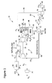
- FIG. 1 is a schematic illustration of an exemplary combined-cycle power generation plant 10 that includes a gas turbine engine 12.
- Gas turbine engine 12 includes a compressor 14 that is coupled to a turbine expander 16 (also referred to in the art as a "turbine") via a rotatable shaft 18.
- Compressor 14 receives air at locally atmospheric pressures and temperatures.
- Turbine expander 16 is coupled to a first electrical generator 20 via a first rotor 22.
- Gas turbine engine 12 also includes a combustor 24 coupled in flow communication with compressor 14.
- Combustor 24 receives at least a portion of recirculated CO 2 compressed by compressor 14 via a conduit 26.
- an air separation unit (ASU) 28 is coupled in flow communication with combustor 24 by a conduit 27.
- ASU air separation unit
- ASU 28 separates N 2 from an air stream 30 and makes air stream 30 rich in O 2 .
- the O 2 rich air stream 30 is directed into combustor 24.
- the N 2 is directed to a compressor 31 through a conduit 29 for compression and sequestration, e.g., by injection underground.
- Combustor 24 is also coupled in flow communication with at least one fuel source 32 and receives fuel from the fuel source, for example, natural gas. The air and fuel are mixed and combusted within combustor 24 which produces hot combustion gases.
- Turbine expander 16 is coupled in flow communication with combustor 24, and turbine expander 16 receives the hot combustion gases via a combustion gas conduit 34. Turbine expander 16 converts the heat energy within the gases to rotational energy. The rotational energy is transmitted to generator 20 via rotor 36, wherein generator 20 converts the rotational energy to electrical energy for transmission to at least one load, including, but not limited to, an electrical power grid.
- plant 10 also includes a steam turbine engine 40. More specifically, steam turbine engine 40 includes a steam turbine 42 coupled to a second electrical generator 44 via a second rotor 46. Power plant 10 also includes a steam generation system 48.
- system 48 includes a heat recovery steam generator (HRSG) 50 that is coupled in flow communication with turbine 16 via at least one conduit 52. HRSG 50 receives exhaust gases from turbine expander 16 via exhaust gas conduit 52. The exhaust from turbine includes O 2 , H 2 O, and CO 2 . HRSG 50 is coupled in flow communication with steam turbine 42 via a steam conduit 54.
- HRSG heat recovery steam generator
- Conduit 54 channels steam from HRSG 50 to steam turbine 42 which converts the thermal energy in the steam to rotational energy.
- the rotational energy is transmitted to generator 44 via rotor 46, wherein generator 44 converts the rotational energy to electrical energy for transmission to at least one load, including, but not limited to, the electrical power grid.
- the exhaust steam from turbine 42 is directed to a condenser 56 where the exhaust steam is condensed to water.
- a pump 58 is coupled in flow communication with condenser 56. Pump 58 pumps the condensed water through a conduit 60 that is coupled in flow communication with HRSG 50.
- the exhaust of the HRSG 50 is directed to a condenser 62 through a conduit 64 that is that is coupled to HRSG 50 and condenser 62.
- Exhaust from HRSG 50 includes O 2 , H 2 O, and CO 2 .
- Water is removed from condenser 62 through an outlet conduit 66.
- a portion of CO 2 is recirculated back to compressor 14 through a conduit 68.
- a separation system 69 is used to separate the excess O 2 from CO 2 by compressing the mixture of CO 2 and O 2 and cooling the compressed mixture.
- Separation system 69 includes a compressor 70, a heat exchanger 74, and a separator 78.
- the remainder of the CO 2 and O 2 is directed to compressor 70 through conduit 72 to compress the CO 2 and O 2 mixture.
- the compressed CO 2 and O 2 mixture is directed to heat exchanger 74 through a conduit 76 to cool down the mixture to temperatures of between about minus 60°C to about minus 120°C.
- the cooled CO 2 and O 2 mixture is directed to separator 78 through a conduit 80 where the CO 2 is separated as either a liquid or a solid.
- a non-condensable O 2 rich stream is recycled to combustor 24 from separator 78 through a conduit 82.
- the liquid/solid CO 2 is pumped from separator 78 through conduit 84 by pump 86 for sequestration.
- a CO 2 and O 2 separation system 90 replaces separation system 69 described above.
- separation system 90 includes a first chamber 92 that includes a oxygen transfer material, for example, a metal-metal oxide material, to remove O 2 from the CO 2 and O 2 mixture described above. Any suitable metal-metal oxide may be used, for example, a Cu-CuO material and the like.
- the oxygen transfer material is oxidized by the O 2 thereby removing the O 2 from the CO 2 and O 2 mixture.
- the CO 2 is removed from first chamber 92 through an outlet conduit 94 for sequestration.
- the oxidized material is directed to a second chamber 96 through a conduit 98 where the oxidized material is reduced by reacting with a fuel, for example natural gas.
- O 2 is removed from the oxidized material by the fuel.
- the fuel and 02 is removed from second chamber 96 through an outlet conduit 100 and recirculated to combustor 24 (shown in Figure 1 ).
- the reduced material is recycled to first chamber 92 through conduit 102.
- O 2 may be removed from the CO 2 and O 2 mixture by adding hydrogen (H 2 ) and combusting the mixture using a burner of catalytic oxidizer.
- the H 2 may be generated bypassing a small amount of fuel, for example natural gas, through a reformer.
- the H 2 may be generated by using electricity generated from generator 20 (shown in Figure 1 ) split water.
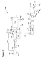
- FIG 3 is a schematic illustration of an exemplary stoichiometric exhaust gas recirculation system (SEGR) 110.
- SEGR 110 includes a first compressor 112 connected to a generator 114 by a first rotatable shaft 116.
- a second compressor 118 is also connected to generator 114 by a second rotatable shaft 120, and to a gas turbine expander 122 by a third rotatable shaft 124.
- a combustor 126 is coupled in flow communication with first compressor 112, and with second compressor 118.
- Combustor 126 receives at least a portion of air compressed by compressors 112 and 118 and via air conduits 128 and 130.
- Combustor 126 is also coupled in flow communication with at least one fuel source 132 and receives fuel from the fuel source, for example, natural gas. The air and fuel are mixed and combusted within combustor 126 which produces hot combustion gases.
- Turbine expander 122 is coupled in flow communication with combustor 126, and turbine expander 122 receives the hot combustion gases via a combustion gas conduit 134. Turbine expander 122 converts the heat energy within the gases to rotational energy.
- SEGR 110 also includes a heat recovery steam generator (HRSG) 136 coupled in flow communication to turbine 122 by an exhaust conduit 138.
- HRSG 136 receives exhaust gases from turbine 122 via exhaust gas conduit 138.
- the exhaust from turbine 112 includes N 2 , H 2 O, and CO 2 .
- HRSG 136 is coupled in flow communication with second compressor 118 via a conduit 140.
- the exhaust gases may be recirculated to second compressor 118 through conduit 140 Water collected in HRSG 136 is removed through outlet conduit 142.
- a portion of the exhaust gases from second compressor 118 is directed to a high pressure HRSG 144 via a conduit 146.
- a separation system 147 is used to separate the excess N 2 from CO 2 from the exhaust gases by compressing the exhaust gases and cooling the compressed gases. Separation system 147 includes HRSG 144, a compressor 148, an intermediate cooler 150, and a separator 152.
- the exhaust gases are directed from HRSG 144 to a compressor 148 via a conduit 154 where the gases are compressed to about 1000 psi to about 2000 psi (about 6,895 kPa to about 13710 kPa).
- the compressed gases are directed to intermediate cooler 150 through a conduit 156 to cool down the gases.
- the cooled gases are directed to separator 152 through a conduit 158 where the CO 2 may be separated using a physical solvent, for example dimethyl-ether-polyethylene-glycol (DEPG) or methyl alcohol, by absorption.
- a non-condensable N 2 rich stream is removed from separator 152 through a conduit 160 to a compressor 162 for sequestration.
- the CO 2 is removed from separator 152 through conduit 164 to a compressor 166 for sequestration.
- intermediate cooler 150 cools the gases to temperatures of between about minus 60°C to about minus 120°C.
- the cooled gases containing CO 2 and N 2 is directed to separator 152 through conduit 158 where the CO 2 is separated as either a liquid or a solid.
- a non-condensable N 2 rich stream is removed from separator 152 through a conduit 160 to a compressor 162 for sequestration.
- the liquid/solid CO 2 is pumped from separator 152 through conduit 164 to a compressor 166 for sequestration.
- approximating language may be applied to modify any quantitative representation that may vary without resulting in a change in the basic function to which it is related. Accordingly, a value modified by a term or terms, such as “about” and “substantially,” may not be limited to the precise value specified, in some cases.
- the modifier "about” used in connection with a quantity is inclusive of the stated value and has the meaning dictated by the context (for example, includes the degree of error associated with the measurement of the particular quantity).
Landscapes
- Engineering & Computer Science (AREA)
- Chemical & Material Sciences (AREA)
- Combustion & Propulsion (AREA)
- Mechanical Engineering (AREA)
- General Engineering & Computer Science (AREA)
- Life Sciences & Earth Sciences (AREA)
- Sustainable Development (AREA)
- Carbon And Carbon Compounds (AREA)
- Treating Waste Gases (AREA)
- Engine Equipment That Uses Special Cycles (AREA)
- Separation Using Semi-Permeable Membranes (AREA)
Applications Claiming Priority (1)
| Application Number | Priority Date | Filing Date | Title |
|---|---|---|---|
| US13/324,466 US20130145773A1 (en) | 2011-12-13 | 2011-12-13 | Method and system for separating co2 from n2 and o2 in a turbine engine system |
Publications (2)
| Publication Number | Publication Date |
|---|---|
| EP2604823A2 true EP2604823A2 (de) | 2013-06-19 |
| EP2604823A3 EP2604823A3 (de) | 2017-09-20 |
Family
ID=47296993
Family Applications (1)
| Application Number | Title | Priority Date | Filing Date |
|---|---|---|---|
| EP12195675.9A Withdrawn EP2604823A3 (de) | 2011-12-13 | 2012-12-05 | Verfahren und System zum Abscheiden von CO2 aus N2 und O2 in einem Turbinenmotorsystem |
Country Status (5)
| Country | Link |
|---|---|
| US (2) | US20130145773A1 (de) |
| EP (1) | EP2604823A3 (de) |
| JP (1) | JP6169840B2 (de) |
| CN (1) | CN103161575A (de) |
| RU (1) | RU2012153420A (de) |
Cited By (1)
| Publication number | Priority date | Publication date | Assignee | Title |
|---|---|---|---|---|
| CN112483350A (zh) * | 2020-11-26 | 2021-03-12 | 清华四川能源互联网研究院 | 一种压缩空气储能排气综合利用系统和方法 |
Families Citing this family (20)
| Publication number | Priority date | Publication date | Assignee | Title |
|---|---|---|---|---|
| SG10201505211UA (en) * | 2010-07-02 | 2015-08-28 | Exxonmobil Upstream Res Co | Low emission triple-cycle power generation systems and methods |
| US9103285B2 (en) * | 2011-01-03 | 2015-08-11 | General Electric Company | Purge system, system including a purge system, and purge method |
| EP2644851A1 (de) * | 2012-03-29 | 2013-10-02 | Alstom Technology Ltd | Verfahren zum Betreiben eines Kombi-Kraftwerks und Kombi-Kraftwerk mit diesem Verfahren |
| DE102013200101A1 (de) * | 2013-01-07 | 2014-07-10 | Siemens Aktiengesellschaft | Gasturbinenanlage als flexibles Ausgleichskraftwerk |
| JP6220586B2 (ja) * | 2013-07-22 | 2017-10-25 | 8 リバーズ キャピタル,エルエルシー | ガスタービン設備 |
| JP6250332B2 (ja) | 2013-08-27 | 2017-12-20 | 8 リバーズ キャピタル,エルエルシー | ガスタービン設備 |
| JP6545436B2 (ja) * | 2014-04-03 | 2019-07-17 | 一般財団法人電力中央研究所 | Co2回収型クローズドサイクルガス化発電システム |
| US9951689B2 (en) | 2014-07-17 | 2018-04-24 | Saudi Arabian Oil Company | Integrated calcium looping combined cycle for sour gas applications |
| PL3344856T3 (pl) | 2015-09-01 | 2020-11-02 | 8 Rivers Capital, Llc | Systemy i sposoby wytwarzania energii przy zastosowaniu zintegrowanych cykli CO<sub>2</sub> |
| DE102016221394A1 (de) * | 2016-10-31 | 2018-05-03 | Robert Bosch Gmbh | Abwärmerückgewinnungssystem mit einem Arbeitsfluidkreislauf und Verfahren zum Betreiben eines derartigen Abwärmerückgewinnungssystems |
| GB2563818A (en) | 2017-05-05 | 2019-01-02 | Ceox Ltd | Mechanical/electrical power generation system |
| JP7025310B2 (ja) * | 2018-09-14 | 2022-02-24 | 一般財団法人電力中央研究所 | ガスタービン複合発電システム、ガスタービン複合発電方法 |
| CN109812304B (zh) * | 2019-03-06 | 2023-08-29 | 上海发电设备成套设计研究院有限责任公司 | 集成二氧化碳循环与液化空气储能的调峰发电系统及方法 |
| US11193421B2 (en) * | 2019-06-07 | 2021-12-07 | Saudi Arabian Oil Company | Cold recycle process for gas turbine inlet air cooling |
| JP7351648B2 (ja) * | 2019-06-13 | 2023-09-27 | 三菱重工業株式会社 | 複合プラント |
| GB201917011D0 (en) * | 2019-11-22 | 2020-01-08 | Rolls Royce Plc | Power generation system with carbon capture |
| CN119678005A (zh) * | 2021-11-02 | 2025-03-21 | 查特能源化工股份有限公司 | 具有废气再循环的碳捕获系统和方法 |
| IT202200001352A1 (it) * | 2022-01-27 | 2023-07-27 | Nuovo Pignone Tecnologie Srl | Un sistema di generazione di potenza comprendente una turbina a gas con generatore di vapore e recupero di calore e cattura di biossido di carbonio, e metodo |
| US12110823B2 (en) * | 2022-11-03 | 2024-10-08 | Saudi Arabian Oil Company | Optimized co-generating system and recovery method for power, water and nitrogen |
| US12416245B2 (en) * | 2023-11-07 | 2025-09-16 | Nuovo Pignone Tecnologie S.r.l. | Dual purpose energy plant |
Family Cites Families (14)
| Publication number | Priority date | Publication date | Assignee | Title |
|---|---|---|---|---|
| US4434613A (en) * | 1981-09-02 | 1984-03-06 | General Electric Company | Closed cycle gas turbine for gaseous production |
| US4498289A (en) * | 1982-12-27 | 1985-02-12 | Ian Osgerby | Carbon dioxide power cycle |
| JPH07213860A (ja) * | 1994-01-28 | 1995-08-15 | Mitsubishi Heavy Ind Ltd | Co2 回収装置及び回収方法 |
| JP2710267B2 (ja) * | 1994-07-12 | 1998-02-10 | 工業技術院長 | 二酸化炭素含有ガスからの二酸化炭素の分離装置と、二酸化炭素分離機能を有する燃焼装置 |
| JPH0914831A (ja) * | 1995-06-27 | 1997-01-17 | Mitsubishi Heavy Ind Ltd | Co2 回収装置及び回収方法 |
| US5724805A (en) * | 1995-08-21 | 1998-03-10 | University Of Massachusetts-Lowell | Power plant with carbon dioxide capture and zero pollutant emissions |
| JPH11169661A (ja) * | 1997-12-12 | 1999-06-29 | Ishikawajima Harima Heavy Ind Co Ltd | 二酸化炭素回収装置 |
| US7381243B2 (en) * | 2002-10-17 | 2008-06-03 | Entegris, Inc. | Method for purifying carbon dioxide |
| WO2006037320A1 (en) * | 2004-10-08 | 2006-04-13 | Union Engineering A/S | Method for recovery of carbon dioxide from a gas |
| US7266940B2 (en) * | 2005-07-08 | 2007-09-11 | General Electric Company | Systems and methods for power generation with carbon dioxide isolation |
| US7824574B2 (en) * | 2006-09-21 | 2010-11-02 | Eltron Research & Development | Cyclic catalytic upgrading of chemical species using metal oxide materials |
| US7966829B2 (en) * | 2006-12-11 | 2011-06-28 | General Electric Company | Method and system for reducing CO2 emissions in a combustion stream |
| DE102009014447A1 (de) * | 2009-03-23 | 2010-09-30 | Man Turbo Ag | Kraftwerk für IGSC-Prozess |
| US20110265445A1 (en) * | 2010-04-30 | 2011-11-03 | General Electric Company | Method for Reducing CO2 Emissions in a Combustion Stream and Industrial Plants Utilizing the Same |
-
2011
- 2011-12-13 US US13/324,466 patent/US20130145773A1/en not_active Abandoned
-
2012
- 2012-12-05 EP EP12195675.9A patent/EP2604823A3/de not_active Withdrawn
- 2012-12-07 JP JP2012267848A patent/JP6169840B2/ja not_active Expired - Fee Related
- 2012-12-12 RU RU2012153420/06A patent/RU2012153420A/ru not_active Application Discontinuation
- 2012-12-13 CN CN201210541022XA patent/CN103161575A/zh active Pending
-
2016
- 2016-01-19 US US15/000,641 patent/US20160131029A1/en not_active Abandoned
Non-Patent Citations (1)
| Title |
|---|
| None |
Cited By (2)
| Publication number | Priority date | Publication date | Assignee | Title |
|---|---|---|---|---|
| CN112483350A (zh) * | 2020-11-26 | 2021-03-12 | 清华四川能源互联网研究院 | 一种压缩空气储能排气综合利用系统和方法 |
| CN112483350B (zh) * | 2020-11-26 | 2022-03-01 | 清华四川能源互联网研究院 | 一种压缩空气储能排气综合利用系统和方法 |
Also Published As
| Publication number | Publication date |
|---|---|
| RU2012153420A (ru) | 2014-06-20 |
| CN103161575A (zh) | 2013-06-19 |
| JP2013124662A (ja) | 2013-06-24 |
| US20160131029A1 (en) | 2016-05-12 |
| JP6169840B2 (ja) | 2017-07-26 |
| US20130145773A1 (en) | 2013-06-13 |
| EP2604823A3 (de) | 2017-09-20 |
Similar Documents
| Publication | Publication Date | Title |
|---|---|---|
| EP2604823A2 (de) | Verfahren und System zum Abscheiden von CO2 aus N2 und O2 in einem Turbinenmotorsystem | |
| EP2588729B1 (de) | Emissionsarme dreifachzyklus-stromerzeugungssysteme und verfahren dafür | |
| CA2801494C (en) | Stoichiometric combustion of enriched air with exhaust gas recirculation | |
| JP5128243B2 (ja) | 発電用ガスタービンを利用した発電所並びにco2排出量の低減法 | |
| AU2011305628B2 (en) | System and method for high efficiency power generation using a nitrogen gas working fluid | |
| EP2588732B1 (de) | Emissionsarme dreifachzyklus-stromerzeugungssysteme und verfahren dafür | |
| US20090193809A1 (en) | Method and system to facilitate combined cycle working fluid modification and combustion thereof | |
| CA2732273C (en) | System and method of operating a power generation system with an alternative working fluid | |
| US20100024378A1 (en) | System and method of operating a gas turbine engine with an alternative working fluid | |
| WO2014124161A1 (en) | System and method for catalyst heat utilization for gas turbine with exhaust gas recirculation | |
| JP2011530033A (ja) | 代替作動流体でガスタービンエンジンを作動させるシステム及び方法 | |
| US11925894B2 (en) | System and method of recovering carbon dioxide from an exhaust gas stream | |
| US10765994B2 (en) | System and method of recovering carbon dioxide from an exhaust gas stream | |
| US8869502B2 (en) | Fuel reformer system for a turbomachine system |
Legal Events
| Date | Code | Title | Description |
|---|---|---|---|
| PUAI | Public reference made under article 153(3) epc to a published international application that has entered the european phase |
Free format text: ORIGINAL CODE: 0009012 |
|
| AK | Designated contracting states |
Kind code of ref document: A2 Designated state(s): AL AT BE BG CH CY CZ DE DK EE ES FI FR GB GR HR HU IE IS IT LI LT LU LV MC MK MT NL NO PL PT RO RS SE SI SK SM TR |
|
| AX | Request for extension of the european patent |
Extension state: BA ME |
|
| RIC1 | Information provided on ipc code assigned before grant |
Ipc: F02C 3/20 20060101AFI20170418BHEP Ipc: F01K 23/10 20060101ALI20170418BHEP Ipc: F02C 3/34 20060101ALI20170418BHEP |
|
| PUAL | Search report despatched |
Free format text: ORIGINAL CODE: 0009013 |
|
| AK | Designated contracting states |
Kind code of ref document: A3 Designated state(s): AL AT BE BG CH CY CZ DE DK EE ES FI FR GB GR HR HU IE IS IT LI LT LU LV MC MK MT NL NO PL PT RO RS SE SI SK SM TR |
|
| AX | Request for extension of the european patent |
Extension state: BA ME |
|
| RIC1 | Information provided on ipc code assigned before grant |
Ipc: F02C 3/20 20060101AFI20170811BHEP Ipc: F02C 3/34 20060101ALI20170811BHEP Ipc: F01K 23/10 20060101ALI20170811BHEP |
|
| STAA | Information on the status of an ep patent application or granted ep patent |
Free format text: STATUS: THE APPLICATION IS DEEMED TO BE WITHDRAWN |
|
| 18D | Application deemed to be withdrawn |
Effective date: 20180321 |