EP2604882A2 - Brems- und/oder Klemmvorrichtung mit Betriebszustandsüberwachung - Google Patents
Brems- und/oder Klemmvorrichtung mit Betriebszustandsüberwachung Download PDFInfo
- Publication number
- EP2604882A2 EP2604882A2 EP12008303.5A EP12008303A EP2604882A2 EP 2604882 A2 EP2604882 A2 EP 2604882A2 EP 12008303 A EP12008303 A EP 12008303A EP 2604882 A2 EP2604882 A2 EP 2604882A2
- Authority
- EP
- European Patent Office
- Prior art keywords
- housing
- braking
- deformation frame
- strain gauges
- guide rail
- Prior art date
- Legal status (The legal status is an assumption and is not a legal conclusion. Google has not performed a legal analysis and makes no representation as to the accuracy of the status listed.)
- Granted
Links
Images


Classifications
-
- F—MECHANICAL ENGINEERING; LIGHTING; HEATING; WEAPONS; BLASTING
- F16—ENGINEERING ELEMENTS AND UNITS; GENERAL MEASURES FOR PRODUCING AND MAINTAINING EFFECTIVE FUNCTIONING OF MACHINES OR INSTALLATIONS; THERMAL INSULATION IN GENERAL
- F16D—COUPLINGS FOR TRANSMITTING ROTATION; CLUTCHES; BRAKES
- F16D63/00—Brakes not otherwise provided for; Brakes combining more than one of the types of groups F16D49/00 - F16D61/00
- F16D63/008—Brakes acting on a linearly moving member
-
- F—MECHANICAL ENGINEERING; LIGHTING; HEATING; WEAPONS; BLASTING
- F16—ENGINEERING ELEMENTS AND UNITS; GENERAL MEASURES FOR PRODUCING AND MAINTAINING EFFECTIVE FUNCTIONING OF MACHINES OR INSTALLATIONS; THERMAL INSULATION IN GENERAL
- F16D—COUPLINGS FOR TRANSMITTING ROTATION; CLUTCHES; BRAKES
- F16D66/00—Arrangements for monitoring working conditions, e.g. wear, temperature
-
- F—MECHANICAL ENGINEERING; LIGHTING; HEATING; WEAPONS; BLASTING
- F16—ENGINEERING ELEMENTS AND UNITS; GENERAL MEASURES FOR PRODUCING AND MAINTAINING EFFECTIVE FUNCTIONING OF MACHINES OR INSTALLATIONS; THERMAL INSULATION IN GENERAL
- F16D—COUPLINGS FOR TRANSMITTING ROTATION; CLUTCHES; BRAKES
- F16D66/00—Arrangements for monitoring working conditions, e.g. wear, temperature
- F16D2066/005—Force, torque, stress or strain
-
- F—MECHANICAL ENGINEERING; LIGHTING; HEATING; WEAPONS; BLASTING
- F16—ENGINEERING ELEMENTS AND UNITS; GENERAL MEASURES FOR PRODUCING AND MAINTAINING EFFECTIVE FUNCTIONING OF MACHINES OR INSTALLATIONS; THERMAL INSULATION IN GENERAL
- F16D—COUPLINGS FOR TRANSMITTING ROTATION; CLUTCHES; BRAKES
- F16D2121/00—Type of actuator operation force
- F16D2121/02—Fluid pressure
- F16D2121/04—Fluid pressure acting on a piston-type actuator, e.g. for liquid pressure
- F16D2121/06—Fluid pressure acting on a piston-type actuator, e.g. for liquid pressure for releasing a normally applied brake
-
- F—MECHANICAL ENGINEERING; LIGHTING; HEATING; WEAPONS; BLASTING
- F16—ENGINEERING ELEMENTS AND UNITS; GENERAL MEASURES FOR PRODUCING AND MAINTAINING EFFECTIVE FUNCTIONING OF MACHINES OR INSTALLATIONS; THERMAL INSULATION IN GENERAL
- F16D—COUPLINGS FOR TRANSMITTING ROTATION; CLUTCHES; BRAKES
- F16D2125/00—Components of actuators
- F16D2125/18—Mechanical mechanisms
- F16D2125/58—Mechanical mechanisms transmitting linear movement
- F16D2125/66—Wedges
Definitions
- the invention relates to a braking and / or clamping device of a slide guided on at least one guide rail, wherein the device comprises at least one operable via a gear Reibgehemme having at least one, mounted in a device housing, can be pressed against the guide rail friction jaw and wherein the help moved by external energy gear for loading and relieving the Reibhememmes per loading and unloading by means of at least one actuator or by means of a spring system comprising at least one spring element, is movable.
- the present invention is based on the problem of equipping a brake and / or clamping device with one or more sensors such that the operating state of the device can be detected and reproduced safely and directly at any time.
- the device housing, attached parts of the device housing or parts installed in the device have at least one surface zone, which stretch, compress or twist when applying a braking and or clamping force.
- at least one of the deformable surface zones at least one strain gauge is arranged.
- the single brake and / or clamping device comprises at least one Reibhememme which is actuated directly or via a transmission.
- the Reibgehemme acts via a friction pad on a guide rail on which a machine or measuring device slide is mounted and guided, which carries this device.
- the single Reibhememme develops its braking and / or clamping effect, for example, by the release of stored in a spring energy stored in the spring energy, which is transmitted via the spline gear on the friction pad.
- the Reibgehemme can be driven directly here, for example by means of a hydraulic cylinder-piston unit.
- gearboxes are installed between the actuator and friction sleeve. This can, for example, slide wedge gears, Exzentergetriebe, lever mechanism, spindle gear and the like.
- the guide rails, on which the friction pads come to rest can e.g. have prismatic, rectangular, round, oval or polygonal cross sections.
- the friction pair is not limited to linear guides. Instead of the mentioned guide rails in the space curved rails can be used.
- sensors in the form of strain gauges are arranged on the device housing, on attachments of the device housing, on friction-inhibiting parts or on parts of possibly existing transmissions.
- the individual strain gauges are arranged there mainly in zones in which stress-induced deformations occur reproducibly and possibly even uniaxially.
- the occurring braking and / or clamping forces stretch, compress or twist the corresponding deformable surface zones, e.g. in the one to three digit micrometer range.
- elastically compliant device housing zones are particularly suitable for strain gauge attachment. These zones are usually large and easily accessible. Also, the wiring of the strain gauges designed simply, since no significant relative movements take place here between the boards carrying the transmitter and the strain gauges.
- device housings - such as the c-shaped housing of the embodiment - is easily on the device housing adaptable deformation frame for receiving the strain gauges and the evaluation used because the device housing deformation can be transferred to it by simple means.
- the entire operating state monitoring is attachable in this case as a modular attachment to the device housing.
- a deformation frame somewhat remote from the heat-loaded friction pads and drives, including its electronics housing, allows the effective attachment of strain gauges for temperature compensation.
- FIGS. 1 . 4 and 5 show a brake and / or clamping device, as used for example in many horizontal or vertical slide, inter alia, in tool and measuring machines.
- the devices of the present embodiment are arranged on the corresponding device carriage (9) in such a way that they engage around the guide rail (1), which predetermines the carriage longitudinal guide, eg with two friction stops (90).
- the device has for this purpose a housing (10), in which two mutually opposite Reibgehemme (90) on both sides of a guide rail (1) are arranged.
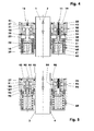
- a deformation frame (70) is flanged, in the interior of which a plurality of strain gauges (85, 86) are arranged, cf.
- FIGS. 2 and 3 Before the deformation frame (70) an electronics housing (110) is mounted, which receives the corresponding evaluation electronics for the interpretation of the deformation.
- the guide rail (1) consists of a rod with an approximately rectangular cross-section, for example. It contacts via its bottom surface (7), for example, the machine bed (5) carrying it. On both sides, it has in each case a guide surface (3, 4) on which the friction jaws (99) of the friction clip (90) are braced during braking.
- the guide rail (1) is surrounded by a housing (10) on both sides.
- the housing (10) two mutually braking and clamping forces generating devices are integrated.
- the in principle c-shaped housing (10) consists of a cuboid, which has transversely to its longitudinal extent a Umgriffsnut (14) which has a rectangular cross-section.
- the groove width is a few millimeters wider than the guide rail width in the area encompassed by the housing (10).
- the groove depth corresponds to e.g. 60% of the case height.
- the housing (10) has eg according to FIG. 4 - Transverse to the longitudinal direction (2) - a total width of about three times Width of the guide rail corresponds.
- the total height of the housing (10) is for example 145% of the guide rail height.
- the length of the housing (10) corresponds for example to 1.2 times the housing height.
- the housing (10) has after FIG. 6 a right (11) and a left housing zone (12), wherein both housing zones (11, 12) each lie next to the guide rail (1). Both zones (11, 12) are connected to one another in the example one-piece housing (10) via a bridge zone (13).
- the bridge zone (13) is, inter alia, also the housing area, via which the device is fastened to the corresponding carriage (9).
- Each housing zone (11, 12), cf. FIGS. 4 and 5 has a multi-stage through-hole (23, 31) whose center line (39) is oriented parallel to the guide longitudinal direction (2), cf. FIG. 4 ,
- the through hole is composed of a guide surface bore (23) and a Käfigsitzausnaturalung (31).
- a locking ring At the other end of the guide surface bore (23) is located as a stop a locking ring (29). Behind the retaining ring (29) is the Käfigsitzaus Principleung (31). It extends over the entire region of a transverse bore bore (23, 31) existing Gehemmebohrung (41).
- the recess (31) is a slot whose width is slightly larger than that of a built-there cage (95). The maximum height of the recess (31) corresponds to the diameter of the guide surface bore (23).
- the recess (31), cf. in FIG. 6 the dashed line in the housing zone (11) has an oval contour in cross-section on the non-rectilinear flanks, in the upper and lower Section sections of the contour of the guide surface bore follows.
- the Gehemmebohrung (41) extending transversely to the stepped bore (23, 31) has a center line (46), the center lines (39) of the stepped holes in the embodiment at a distance of e.g. 1 mm crosses.
- the center line (46) intersects the center line (2) of the guide rail (1).
- Each Gehemmebohrung (41) has three graduated areas, see. FIG. 5 , From the outside of the housing, these are a main bore (42), a pressure piece guide bore (44) and an outlet bore (45).
- the main bore (42) intersects with the cage seat recess (31). In the housing zones (11, 12), see FIG. 4 , you can see the penetration lines (43).
- the adjusting screw (91) is a cylindrical disc, which has bores for the engagement of a tenon wrench on the outer end face, cf. FIG. 1 , It has an external thread that ends in an annular groove. In the groove a squeeze ring is embedded as a screw lock.
- the pressure piece (96) is a cylindrical piston with an integrally formed piston rod.
- the piston rod projects out of the outlet bore (45) when the friction clip (90) is actuated.
- an elastic remindhubring (98) sits with eg rectangular single cross section.
- a friction jaw (99) - as a front part of the pressure piece (96) - arranged, see. FIG. 6 .
- a powder-metallurgically produced friction material based on bronze can be used for the friction lining.
- the friction material contains eg additional ceramic components.
- the sliding wedge (92) is e.g. a trapezoidal body with rectangular cross sections. He is rigid, e.g. by means of a screw (54), attached to a guide piston (51) mounted in the guide surface bore (23).
- the sliding wedge (92) which also represents the piston rod of the guide piston (51) equipped with a piston seal (52), has i.a. a support (94) and a wedge surface (93). Both surfaces (93, 94) are rectangular and e.g. plan.
- the respective wedge surface (93) facing the pressure piece (96) closes with it, e.g. an acute angle of 1 to 5 degrees.
- the support surface (94) extends parallel to the end face of the adjacent adjusting screw (91).
- the cross sections of the spline (92) taper linearly with increasing distance away from the piston rod side of the guide piston (51).
- the cage (95) surrounding the sliding wedge (92) has a cross-sectional shape which fits into the cage seat recess (31) with play. He has the center - parallel to the longitudinal direction - to Receiving the sliding wedge (92) has a rectangular opening, which is slightly larger than the largest cross section of the sliding wedge (92). Across this breakthrough is located off-center also a rectangular breakthrough. The latter serves to receive the cylindrical rollers (106, 107).
- the spring sleeve (61) of the spring accumulator (60) is screwed.
- the spring box (61) having a flat bottom (62) the helical compression spring (63) is mounted, which acts on the front side of the guide piston (51) when needed.
- the spring box (61) is a corresponding with the environment relief bore, so as not to hinder the compressed air-loaded working stroke of the guide piston (51).
- the device is according to the FIG. 4 in the unactuated state.
- the compressed air loaded, the helical compression spring (63) exciting guide piston (51) uses the housing (10) located end face of the spring sleeve (61) as a stop.
- the sliding wedge (92) is in its rear position.
- the cylindrical rollers (106, 107) sit unloaded in the cage (95).
- the individual cage (95) is in each case by two coil springs (27) which are inserted in unrepresented cage holes and are supported on the bottom of Käfigsitzaus Principleung (31), pressed against a stopper serving as a circlip (29).
- the spatially upper coil springs (28) - on the left side of the figure - omitted only for clarity.
- the respective thrust piece (96) is generally not relieved at the friction pad (99) when the return stroke ring (98) is largely unloaded but still in abutment.
- the gearhubring (98) still has at least as much bias that the pressure piece (96), the cylindrical rollers (106, 107) and the sliding wedge (92) rest against the adjusting screw (91) without play.
- the friction pads (99) press against the guide rail (1) with such great force that the device housing (10) deforms measurably elastically.
- the two housing zones (11) and (12), cf. FIG. 6 the desire to move away from each other.
- the above the guide rail (1) located bridge zone (13), which here is the function of a classic bending beam is assigned, charged to bending.
- the underside (15) of the bridge zone (13) is partially stretched to within the three-digit micrometer range, while the top (16) of the housing is compressed, for example in the two-digit micrometer range.
- the shape change which has the effect of stretching or compression can be detected with the aid of strain gauges and downstream evaluation electronics.
- strain gauges by the strain or compression of the corresponding housing portions a change in resistance, which can be output after appropriate preparation as a change in force.
- the strain gauges are connected, for example, in quarter, half or full bridges.
- strain gauges are arranged transversely to the guide longitudinal direction (2). At this bottom (15) they are protected from possible damage. There, they are also not in the way of installation of the device in the respective machine in the way.
- the strain gauges are integrated in a part attachable to the device housing (10), a special deformation frame (70).
- the deformation frame (70), which is fixed to the front end face (18) of the housing (10), is essentially a cuboidal plate, which is connected to e.g. four larger (71, 72, 73, 75) and eight smaller recesses (81, 82, 83, 84) is provided.
- Two identical, circular recesses (72, 73) serve as a passage for the spring tins (61). Its inner diameter is about two tenths of a millimeter larger than the outer diameter of the spring sleeves (61).
- Another recess is the rectangular groove (71) with which the deformation frame (70) surrounds the guide rail (1).
- FIG. 2 in which the front side (65) of the deformation frame (70) is shown, located above the rectangular groove (71) is a slot-like sensor recess (75). On the flat inner sides (77, 79) of this recess (75) strain gauges (85, 86) are glued.
- a pressure web (78) and a tensile web (76) are formed there. Both webs (76, 78) each have the shape of a cuboid. They are 18 mm long and 8 mm wide according to the embodiment.
- the after FIG. 2 The upper pressure bar (78) has a wall thickness of 2 mm, while the lower tension bar (76) has a wall thickness of 1.5 mm.
- the deformation frame (70) has four mounting holes (81, 82) in the lateral outer area. With the help of the cheese head screws (89) he is screwed on this on the housing (10). To FIG. 3 is located in the deformation frame (70) on both sides of the rectangular groove (71), near the bottom (67) of the deformation frame (70), one each from the back (66) drilled blind hole (84). In these Padedbohrept stuck dowel pins, which protrude after assembly in corresponding Plangebohrache of the housing (10).
- the cuboid electronics housing (110) is screwed to the deformation frame (70) with an end flange (111) such that the housing (110) is located above the guide rail (1) when the deformation frame (70) is mounted.
- the housing (110) has on its side facing away from the guide rail (1) a cover (112) in which two light-emitting diodes (115, 116) are arranged.
- the one light-emitting diode (115) lights up green, for example, when the friction clamps (90) are unconfirmed.
- the other light-emitting diode (116) lights red, for example, when the housing (10) has deformed measurably under the clamping action of the friction clip (90).
- a connector (118) via which on the one hand the electronics are powered and on the other is at least one signal output.
- the signal output transmits, for example, the operating state of the brake and / or clamping device to the controller of the machine carrying the device.
Landscapes
- Engineering & Computer Science (AREA)
- General Engineering & Computer Science (AREA)
- Mechanical Engineering (AREA)
- Bearings For Parts Moving Linearly (AREA)
- Braking Arrangements (AREA)
- Machine Tool Units (AREA)
Abstract
Description
- Die Erfindung betrifft eine Brems- und/oder Klemmvorrichtung eines an mindestens einer Führungsschiene geführten Schlittens, wobei die Vorrichtung mindestens ein über ein Getriebe betätigbares Reibgehemme umfasst, das wenigstens eine, in einem Vorrichtungsgehäuse gelagerte, an die Führungsschiene anpressbare Reibbacke aufweist und wobei das mit Hilfe von Fremdenergie bewegte Getriebe zur Be- und zur Entlastung des Reibgehemmes pro Be- und Entlastungsrichtung mittels mindestens eines Stellgliedes oder mittels eines Federsystems, das mindestens ein Federelement umfasst, bewegbar ist.
- Aus der
DE 102 07 605 C1 ist eine vergleichbare Brems- und/oder Klemmvorrichtung bekannt. Die einzelnen Reibgehemme werden mit Hilfe eines Federspeichers und eines Schiebekeilgetriebes zugestellt. Zum Öffnen der Reibgehemme werden pneumatisch betätigte Zylinder-Kolben-Einheiten verwendet. Durch eine Überwachung der Druckluft der Zylinder-Kolben-Einheiten oder deren Druckluftzuleitungen wird auf die Offenstellung der Reibgehemme geschlossen. - Der vorliegenden Erfindung liegt die Problemstellung zugrunde, eine Brems- und/oder Klemmvorrichtung so mit einem oder mehreren Sensoren auszustatten, dass der Betriebszustand der Vorrichtung zu jedem Zeitpunkt sicher und direkt erfasst sowie wiedergegeben werden kann.
- Diese Problemstellung wird mit den Merkmalen des Patentanspruchs 1 gelöst. Dazu weist das Vorrichtungsgehäuse, angebaute Teile des Vorrichtungsgehäuses oder in der Vorrichtung verbaute Teile mindestens eine Oberflächenzone auf, die sich beim Aufbringen einer Brems- und oder Klemmkraft dehnen, stauchen oder tordieren. In mindestens einer der verformbaren Oberflächenzonen ist mindestens ein Dehnmeßstreifen angeordnet.
- Die einzelne Brems- und/oder Klemmvorrichtung umfasst mindestens ein Reibgehemme, das direkt oder über ein Getriebe betätigbar ist. Das Reibgehemme wirkt über eine Reibbacke auf eine Führungsschiene, auf der ein Maschinen- oder Messgeräteschlitten gelagert und geführt ist, der diese Vorrichtung trägt. Das einzelne Reibgehemme entwickelt seine Brems- und/oder Klemmwirkung beispielsweise durch das Freisetzen von in einem Federspeicher gespeicherten Federenergie, die über das Schiebekeilgetriebe auf die Reibbacke übertragen wird.
- Das Reibgehemme kann hierbei direkt angetrieben werden, z.B. mittels einer hydraulischen Zylinder-Kolben-Einheit. Bei Stellgliedern kleinerer Schubkraft werden zwischen das Stellglied und das Reibgehemme Getriebe eingebaut. Das können z.B. Schiebekeilgetriebe, Exzentergetriebe, Hebelgetriebe, Spindelgetriebe und dergleichen sein.
- Die Führungsschienen, an denen die Reibbacken zur Anlage kommen, können z.B. prismatische, rechteckförmige, runde, ovale oder polygonförmige Querschnitte haben. Auch ist die Reibpaarung nicht auf Linearführungen begrenzt. Anstelle der erwähnten Führungsschienen können im Raum gekrümmte Schienen verwendet werden.
- Zur Betriebszustandsüberwachung werden bei der vorliegenden Erfindung innerhalb der Brems- und/oder Klemmvorrichtung betriebsbedingte elastische Verformungen erfasst und ausgewertet. Dazu werden Sensoren in Form von Dehnmeßstreifen am Vorrichtungsgehäuse, an Anbauten des Vorrichtungsgehäuses, an Reibgehemmeteilen oder an Teilen von ggf. vorhandenen Getrieben angeordnet. Die einzelnen Dehnmeßstreifen werden dort vorwiegend in Zonen angeordnet, in denen belastungsbedingte Verformungen reproduzierbar und ggf. sogar einachsig auftreten. Die auftretenden Brems- und oder Klemmkräfte dehnen, stauchen oder tordieren die entsprechenden verformbaren Oberflächenzonen z.B. im ein- bis dreistelligen Mikrometerbereich.
- Bei Brems- und/oder Klemmvorrichtungen, deren Vorrichtungsgehäuse sich beim Brems- und/oder Klemmvorgang elastisch verformen, sind elastisch nachgiebige Vorrichtungsgehäusezonen zur Dehnmeßstreifenanbringung besonders geeignet. Diese Zonen sind in der Regel großflächig und gut zugänglich. Auch gestaltet sich die Verdrahtung der Dehnmeßstreifen einfach, da hier zwischen den die Auswerteelektronik tragenden Platinen und den Dehnmeßstreifen keine nennenswerten Relativbewegungen stattfinden.
- Bei Vorrichtungsgehäusen - wie z.B. dem c-förmigen Gehäuse des Ausführungsbeispiels - ist problemlos ein am Vorrichtungsgehäuse adaptierbarer Verformungsrahmen zur Aufnahme der Dehnmeßstreifen und der Auswerteelektronik verwendbar, da auf ihn die Vorrichtungsgehäuseverformung mit einfachen Mitteln übertragbar ist. Die gesamte Betriebszustandsüberwachung ist in diesem Fall als modulares Anbauteil am Vorrichtungsgehäuse anbringbar.
- Ein von den wärmebelasteten Reibgehemmen und Antrieben etwas entfernt gelegener Verformungsrahmen, einschließlich seines Elektronikgehäuses, ermöglicht die wirksame Anbringung von Dehnmeßstreifen für die Temperaturkompensation.
- Weitere Einzelheiten der Erfindung ergeben sich aus den Unteransprüchen und der nachfolgenden Beschreibung einer schematisch dargestellten Ausführungsform.
- Figur 1:
- Brems- und/oder Klemmvorrichtung mit externer Sensoreinheit;
- Figur 2:
- Verformungsrahmen mit Dehnmeßstreifen;
- Figur 3:
- Verformungsrahmen mit Dehnmeßstreifen, wie
Figur 2 , jedoch von unten; - Figur 4:
- Brems- und/oder Klemmvorrichtung im Längsschnitt, unbetätigt;
- Figur 5:
- wie
Figur 4 , jedoch betätigt; - Figur 6:
- Vorderansicht der Brems- und/oder Klemmvorrichtung.
- Die
Figuren 1 ,4 und 5 zeigen eine Brems- und/oder Klemmvorrichtung, wie sie beispielsweise in vielen Horizontal- oder Vertikalschlitten u.a. in Werkzeug- und Messmaschinen verwendet wird. Die Vorrichtungen der vorliegenden Ausführungsform sind hierbei am entsprechenden Geräteschlitten (9) so angeordnet, dass sie die - die Schlittenlängsführung vorgebende - Führungsschiene (1), z.B. mit zwei Reibgehemmen (90), umgreifen. Die Vorrichtung hat dazu ein Gehäuse (10), in dem zwei einander gegenüberliegende Reibgehemme (90) beidseits einer Führungsschiene (1) angeordnet sind. An der Vorderseite (18) des Gehäuses (10) ist ein Verformungsrahmen (70) angeflanscht, in dessen Inneren mehrere Dehnmeßstreifen (85, 86) angeordnet sind, vgl.Figuren 2 und 3 . Vor dem Verformungsrahmen (70) ist ein Elektronikgehäuse (110) montiert, das die entsprechende Auswerteelektronik zur Interpretation der Verformung aufnimmt. - In den
Figuren 4 und 5 ist u.a. ein Abschnitt einer Führungsschiene (1) dargestellt. Die Führungsschiene (1) besteht aus einem Stab mit einem z.B. annähernd rechteckigen Querschnitt. Sie kontaktiert über ihre Bodenfläche (7) z.B. das sie tragende Maschinenbett (5). Beidseitig hat sie jeweils eine Führungsfläche (3, 4), an der sich beim Bremsen die Reibbacken (99) der Reibgehemme (90) abstützen. - Die Führungsschiene (1) wird von einem Gehäuse (10) beidseitig umgriffen. Im Gehäuse (10) sind zwei gegeneinander Brems- und Klemmkräfte erzeugende Vorrichtungen integriert. Das im Prinzip c-förmige Gehäuse (10) besteht aus einem Quader, der quer zu seiner Längsausdehnung eine Umgriffsnut (14) aufweist, die einen rechteckförmigen Querschnitt hat. Die Nutbreite ist wenige Millimeter breiter als die Führungsschienenbreite in dem vom Gehäuse (10) umgriffenen Bereich. Die Nuttiefe entspricht z.B. 60% der Gehäusehöhe.
- Das Gehäuse (10) hat z.B. gemäß
Figur 4 - quer zur Führungslängsrichtung (2) - eine Gesamtbreite, die ca. der dreifachen Breite der Führungsschiene entspricht. Die Gesamthöhe des Gehäuses (10) beträgt z.B. 145% der Führungsschienenhöhe. Die Länge des Gehäuses (10) entspricht beispielsweise dem 1,2-fachen der Gehäusehöhe. - Das Gehäuse (10) hat nach
Figur 6 eine rechte (11) und eine linke Gehäusezone (12), wobei beide Gehäusezonen (11, 12) jeweils neben der Führungsschiene (1) liegen. Beide Zonen (11, 12) sind im z.B. einteiligen Gehäuse (10) über eine Brückenzone (13) miteinander verbunden. Die Brückenzone (13) ist u.a. auch der Gehäusebereich, über den die Vorrichtung am entsprechenden Schlitten (9) befestigt wird. Jede Gehäusezone (11, 12), vgl.Figuren 4 und 5 , weist eine mehrstufige Durchgangsbohrung (23, 31) auf, deren Mittellinie (39) parallel zur Führungslängsrichtung (2) orientiert ist, vgl.Figur 4 . Die Durchgangsbohrung setzt sich aus einer Führungsflächenbohrung (23)und einer Käfigsitzausnehmung (31) zusammen. - Im Bereich der Öffnung der Führungsflächenbohrung (23) befindet sich ein Feingewinde und eine einen Quetschring (24) aufnehmende Nut.
- Am anderen Ende der Führungsflächenbohrung (23) befindet sich als Anschlag ein Sicherungsring (29). Hinter dem Sicherungsring (29) liegt die Käfigsitzausnehmung (31). Sie erstreckt sich über den gesamten Bereich einer quer zur Stufenbohrung (23, 31) vorhandenen Gehemmebohrung (41). Die Ausnehmung (31) ist ein Langloch, dessen Breite geringfügig größer ist als die eines dort eingebauten Käfigs (95). Die maximale Höhe der Ausnehmung (31) entspricht dem Durchmesser der Führungsflächenbohrung (23). Die Ausnehmung (31), vgl. in
Figur 6 die gestrichelte Linie in der Gehäusezone (11), hat im Querschnitt an den nicht geradlinigen Flanken eine ovale Kontur, die im oberen und unteren Bereich abschnittsweise der Kontur der Führungsflächenbohrung folgt. - Die quer zur Stufenbohrung (23, 31) verlaufende Gehemmebohrung (41) hat eine Mittellinie (46), die die Mittellinien (39) der Stufenbohrungen im Ausführungsbeispiel im Abstand von z.B. 1 mm kreuzt. Beispielsweise schneidet die Mittellinie (46) die Mittellinie (2) der Führungsschiene (1).
- Jede Gehemmebohrung (41) hat drei abgestufte Bereiche, vgl.
Figur 5 . Von der Gehäuseaußenseite her sind das eine Hauptbohrung (42), eine Druckstückführungsbohrung (44) und eine Austrittsbohrung (45). Die Hauptbohrung (42) schneidet sich mit der Käfigsitzausnehmung (31). In den Gehäusezonen (11, 12), sieheFigur 4 , kann man die Durchdringungslinien (43) erkennen. - In diesem Bereich sitzt der Käfig (95), der zwei Zylinderrollen (106, 107) lagert. Beide Zylinderrollen (106, 107) liegen an einem Schiebekeil (92) eines Schiebekeilgetriebes an. Die außenliegende Zylinderrolle (106) stützt sich an einer Einstellschraube (91) ab, während die innenliegende Zylinderrolle (107) an einem hier unbelasteten Druckstück (96) anliegt.
- Im Bereich der Einstellschraube (91) trägt die Hauptbohrung (42) ein Feingewinde. Die Einstellschraube (91) ist eine zylindrische Scheibe, die an der äußeren Stirnfläche Bohrungen für den Eingriff eines Zapfenschlüssels aufweist, vgl.
Figur 1 . Sie hat ein Außengewinde, das in einer Ringnut endet. In der Nut ist ein Quetschring als Schraubensicherung eingelassen. - Das Druckstück (96) ist ein zylindrischer Kolben mit einer angeformten Kolbenstange. Die Kolbenstange ragt bei betätigtem Reibgehemme (90) aus der Austrittsbohrung (45) heraus. Am Übergang der Kolbenstange zum Kolben befindet sich eine Stirnnut, in der ein elastischer Rückhubring (98) mit z.B. rechteckigem Einzelquerschnitt sitzt.
- Vor der außenseitigen Stirnfläche des Druckstückes (96) ist in der Umgriffsnut (14) eine Reibbacke (99) - als vorderes Teil des Druckstückes (96) - angeordnet, vgl.
Figur 6 . In die Reibbacke (99) ist beispielsweise ein aus dieser zumindest geringfügig herausragender Reibbelag eingepresst und dort ggf. verklebt oder verlötet. Für den Reibbelag kann ein pulvermetallurgisch hergestellter Reibwerkstoff auf Bronzebasis verwendet werden. Der Reibwerkstoff enthält z.B. zusätzlich keramische Bestandteile. - Zwischen dem Druckstück (96) und der Einstellschraube (91) ist der Schiebekeil (92) umgeben von dem Käfig (95) angeordnet. Der Schiebekeil (92) ist z.B. ein trapezförmiger Körper mit rechteckigen Querschnitten. Er ist starr, z.B. mittels einer Schraube (54), an einem in der Führungsflächenbohrung (23) gelagerten Führungskolben (51) befestigt. Der Schiebekeil (92), der auch die Kolbenstange des mit einer Kolbendichtung (52) ausgestatteten Führungskolbens (51) darstellt, hat u.a. eine Stütz-(94) und eine Keilfläche (93). Beide Flächen (93, 94) sind rechteckig und z.B. plan. Die jeweils dem Druckstück (96) zugewandte Keilfläche (93) schließt mit diesem z.B. einen spitzen Winkel von 1 bis 5 Winkelgraden ein. Die Stützfläche (94) verläuft parallel zur Stirnfläche der benachbarten Einstellschraube (91). Beispielsweise verjüngen sich die Querschnitte des Schiebekeils (92) linear mit zunehmendem Abstand weg von der Kolbenstangenseite des Führungskolbens (51).
- Der den Schiebekeil (92) umgebende Käfig (95) hat eine Querschnittsform, die mit Spiel in die Käfigsitzausnehmung (31) passt. Er hat mittig - parallel zur Führungslängsrichtung - zur Aufnahme des Schiebekeils (92) einen rechteckigen Durchbruch, der geringfügig größer ist als der größte Querschnitt des Schiebekeils (92). Quer zu diesem Durchbruch befindet sich außermittig ein ebenfalls rechteckiger Durchbruch. Letzterer dient der Aufnahme der Zylinderrollen (106, 107).
- Im Feingewinde der Führungsflächenbohrung (23) ist die Federbüchse (61) des Federspeichers (60) eingeschraubt. In der Federbüchse (61), die einen planen Boden (62) hat, ist die Schraubendruckfeder (63) gelagert, die bei Bedarf auf die Vorderseite des Führungskolbens (51) wirkt. In der Federbüchse (61) befindet sich eine mit der Umgebung korrespondierende Entlastungsbohrung, um den druckluftbelasteten Arbeitshub des Führungskolbens (51) nicht zu behindern.
- Während des Normalbetriebes des die Vorrichtung tragenden Schlittens (9) befindet sich die Vorrichtung entsprechend der
Figur 4 im unbetätigten Zustand. Der druckluftbelastete, die Schraubendruckfeder (63) spannende Führungskolben (51) nutzt die im Gehäuse (10) gelegene Stirnfläche der Federbüchse (61) als Anschlag. Der Schiebekeil (92) befindet sich in seiner hinteren Position. Die Zylinderrollen (106, 107) sitzen unbelastet im Käfig (95). Der einzelne Käfig (95) wird jeweils von zwei Schraubenfedern (27), die in nichtdargestellten Käfigbohrungen eingesteckt sind und sich am Boden der Käfigsitzausnehmung (31) abstützen, gegen einen als Anschlag dienenden Sicherungsring (29) gedrückt. In denFiguren 4 und 5 sind die räumlich oben liegenden Schraubenfedern (28) - auf der jeweils linken Figurenseite - nur zur Verdeutlichung weggelassen. Das jeweilige Druckstück (96) liegt bei weitgehend entlastetem, aber dennoch anliegendem Rückhubring (98) in der Regel nicht an der Reibbacke (99) an. Der Rückhubring (98) hat noch mindestens so viel Vorspannung, dass das Druckstück (96), die Zylinderrollen (106, 107) und der Schiebekeil (92) spielfrei an der Einstellschraube (91) anliegen. - Werden nun bei der Vorrichtung nach
Figur 5 die unter Druckluft stehende Führungsflächenbohrung (23), Käfigsitzausnehmung (31) und Gehemmebohrung (41) entlüftet, wird ein Bremsvorgang bzw. ein Festklemmen eingeleitet. Die einzelne sich entspannende Schraubendruckfeder (63) des jeweiligen Federspeichers (60) schiebt mittels des Führungskolbens (51) den Schiebekeil (92) in die Käfigsitzausnehmung (31) hinein, vgl.Figur 5 . Solange die Kraft der jeweiligen Schraubendruckfeder (63) wirkt, liegen die Reibbacken (99) an der Führungsschiene (1) an. - Zum Lösen der Klemmung werden die Bohrungen (23, 31, 41) mit Druckluft beaufschlagt, womit die Führungskolben (51) die Schiebekeile (92) zur Entlastung der Reibgehemme (90) zurückziehen und zugleich die Federspeicher (60) wieder spannen.
- Während der Brems- und/oder Klemmbewegung pressen sich die Reibbelege (99) mit so großer Kraft gegen die Führungsschiene (1), dass sich das Vorrichtungsgehäuse (10) meßbar elastisch verformt. Hierbei haben die beiden Gehäusezonen (11) und (12), vgl.
Figur 6 , das Bestreben, sich voneinander zu entfernen. Dadurch wird die oberhalb der Führungsschiene (1) gelegene Brückenzone (13), der hier die Funktion eines klassischen Biegebalkens zuteil wird, auf Biegung belastet. Die Unterseite (15) der Brückenzone (13) wird teilweise bis in den dreistelligen Mikrometerbereich gedehnt, während die Oberseite (16) des Gehäuses z.B. im zweistelligen Mikrometerbereich gestaucht wird. - Die sich als Dehnung oder Stauchung auswirkende Formänderung ist mit Hilfe von Dehnmeßstreifen und einer nachgeordneten Auswerteelektronik erfassbar. Die einzelnen Dehnmeßstreifen erfahren durch die Dehnung oder Stauchung der entsprechenden Gehäusebereiche eine Widerstandsänderung, die nach entsprechender Aufbereitung als Kraftänderung ausgebbar ist. Die Dehnmeßstreifen werden dabei z.B. in Viertel- Halb- oder Vollbrücken verschaltet.
- Unabhängig vom Ausführungsbeispiel können, speziell an der Unterseite (15) der Brückenzone (13), Dehnmeßstreifen quer zur Führungslängsrichtung (2) angeordnet werden. An dieser Unterseite (15) sind sie geschützt vor möglichen Beschädigungen. Dort sind sie zudem beim Einbau der Vorrichtung in die jeweilige Maschine nicht im Weg.
- Gemäß dem Ausführungsbeispiel sind die Dehnmeßstreifen in einem am Vorrichtungsgehäuse (10) anbaubaren Teil, einem speziellen Verformungsrahmen (70), integriert. Der Verformungsrahmen (70), der an der vorderen Stirnseite (18) des Gehäuses (10) befestigt ist, ist im Wesentlichen eine quaderförmige Platte, die mit z.B. vier größeren (71, 72, 73, 75) und acht kleineren Ausnehmungen (81, 82, 83, 84) versehen ist. Zwei formgleiche, kreisrunde Ausnehmungen (72, 73) dienen als Durchlass für die Federbüchsen (61). Ihr Innendurchmesser ist ca. zwei zehntel Millimeter größer als der Außendurchmesser der Federbüchsen (61). Eine weitere Ausnehmung ist die Rechtecknut (71), mit der der Verformungsrahmen (70) die Führungsschiene (1) umgibt.
- Nach
Figur 2 , in der die Vorderseite (65) des Verformungsrahmens (70) dargestellt ist, befindet sich oberhalb der Rechtecknut (71) eine langlochartige Sensorenausnehmung (75). An den planen Innenseiten (77, 79) dieser Ausnehmung (75) sind Dehnmeßstreifen (85, 86) aufgeklebt. - Durch die Form und die Anordnung der Sensorenausnehmung (75) im Verformungsrahmen (70) entstehen dort ein Drucksteg (78) und ein Zugsteg (76). Beide Stege (76, 78) haben jeweils die Form eines Quaders. Sie sind gemäß dem Ausführungsbeispiel 18 mm lang und 8 mm breit. Der nach
Figur 2 oben liegende Drucksteg (78) hat eine Wandstärke von 2 mm, während der darunter liegende Zugsteg (76) eine Wandstärke von 1,5 mm aufweist. - Der Verformungsrahmen (70) hat im seitlichen Außenbereich vier Befestigungsbohrungen (81, 82). Mit Hilfe der Zylinderschrauben (89) ist er über diese am Gehäuse (10) verschraubt. Nach
Figur 3 befindet sich im Verformungsrahmen (70) beidseits der Rechtecknut (71), in der Nähe der Unterseite (67) des Verformungsrahmens (70), je eine von der Rückseite (66) gebohrte Sacklochbohrung (84). In diesen Paßbohrungen stecken Paßstifte, die nach der Montage in entsprechende Paßbohrungen des Gehäuses (10) hineinragen. - Auf beiden Seiten der Sensorenausnehmung (75) ist jeweils eine Gewindebohrung (83) zur Befestigung des Elektronikgehäuses (110) mittels der Schrauben (119) angeordnet, vgl.
Figur 1 . - Das quaderförmige Elektronikgehäuse (110) ist mit einem stirnseitigen Flansch (111) am Verformungsrahmen (70) so festgeschraubt, dass sich das Gehäuse (110) bei montiertem Verformungsrahmen (70) oberhalb der Führungsschiene (1) befindet. Das Gehäuse (110) hat auf seiner der Führungsschiene (1) abgewandten Seite einen Deckel (112), in dem zwei Leuchtdioden (115, 116) angeordnet sind. Die eine Leuchtdiode (115) leuchtet z.B. grün, wenn die Reibgehemme (90) unbetätigt sind. Die andere Leuchtdiode (116) leuchtet z.B. rot, wenn sich das Gehäuse (10) unter der Klemmwirkung der Reibgehemme (90) meßbar verformt hat.
- Selbstverständlich können dort weitere Leuchtdioden angeordnet werden, sofern weitere Betriebszustände optisch darstellbar sein sollen. U.a. ist es denkbar, verschiedene Kraftgrenzwerte auszuwerten und anzuzeigen. Sind hierbei diese Kraftgrenzwerte kleiner als die vorgegebene Maximalkraft, kann so festgestellt werden, dass z.B. nur ein Reibgehemme arbeitet, oder dass beispielsweise innerhalb der Vorrichtung eine klemmkraftmindernde Reibung auftritt. Auch ist es denkbar, die ermittelte Klemmkraft dazu zu benutzen, um das mit Fremdenergie betätigte Stellglied so zu regeln, dass eine bestimmte Brems- und/oder Klemmkraft eingehalten wird. Zudem ist es über eine solche Regelung möglich, die Bremsbeschleunigung der Bremsvorgänge zu variieren.
- In der Nähe der Leuchtdioden (115, 116) befindet sich seitlich am Gehäuse (110) ein Anschlussstecker (118), über den zum einen die Elektronik mit Strom versorgt wird und auf den zum anderen mindestens ein Signalausgang gelegt ist. Der Signalausgang übermittelt z.B. den Betriebszustand der Brems- und/oder Klemmvorrichtung an die Steuerung der die Vorrichtung tragenden Maschine.
-
- 1
- Führungsschiene, doppeltrapezförmig
- 2
- Führungslängsrichtung, Mittellinie
- 3, 4
- Führungsflächen
- 5
- Maschinenbett
- 7
- Bodenfläche
- 9
- Geräteschlitten
- 10
- Vorrichtungsgehäuse, Gehäuse
- 11
- Gehäusezone, rechts
- 12
- Gehäusezone, links
- 13
- Brückenzone
- 14
- Umgriffsnut
- 15
- Unterseite, Gehäusezugzone,
- 16
- Oberseite
- 18
- Stirnseite, Vorderseite
- 19
- Stirnseite, Rückseite
- 23
- Führungsflächenbohrung
- 24
- Quetschring
- 27
- Schraubenfeder für Rückhub von (95), unten
- 28
- Schraubenfeder für Rückhub von (92), oben
- 29
- Sicherungsring
- 31
- Käfigsitzausnehmung, Ausnehmung
- 39
- Mittellinie
- 41
- Gehemmebohrung
- 42
- Hauptbohrung
- 43
- Durchdringungslinie
- 44
- Druckstückführungsbohrung
- 45
- Austrittsbohrung
- 46
- Mittellinie
- 50
- Stellglied, Zylinder-Kolben-Einheit
- 51
- Führungskolben, Pneumatikkolben
- 52
- Kolbendichtung, Quadring
- 54
- Schraube
- 58
- Druckluftanschluss
- 60
- Federspeicher
- 61
- Federbüchse
- 62
- Federbüchsenboden
- 63
- Schraubendruckfeder
- 65
- Vorderseite
- 66
- Rückseite
- 67
- Unterseite
- 70
- Verformungsrahmen, Sensoreinheit
- 71
- Rechtecknut
- 72, 73
- Federbüchsenausnehmungen
- 75
- Sensorenausnehmung
- 76
- Oberflächenzone, Zugsteg
- 77
- Innenfläche, Innenseite
- 78
- Oberflächenzone, Drucksteg
- 79
- Innenfläche, Innenseite
- 81, 82
- Befestigungsbohrungen
- 83
- Verschraubungsbohrung
- 84
- Sacklochbohrung für Paßstifte, Paßbohrung
- 85
- Dehnmeßstreifen in Zugzone
- 86
- Dehnmeßstreifen in Druckzone
- 89
- Zylinderschrauben
- 90
- Reibgehemme
- 91
- Einstellschraube
- 92
- Schiebekeil
- 93
- Keilfläche
- 94
- Stützfläche
- 95
- Käfig
- 96
- Druckstück
- 98
- Rückhubring, elastisch
- 99
- Reibbacke
- 106
- Zylinderrolle, außenliegend
- 107
- Zylinderrolle, innenliegend
- 110
- Elektronikgehäuse, Sensoreinheit
- 111
- Gehäuseflansch
- 112
- Deckel
- 115
- LED für die Offenstellung
- 116
- LED für die Geschlossenstellung
- 118
- Anschluss, elektrisch
- 119
- Befestigungsschrauben
Claims (10)
- Brems- und/oder Klemmvorrichtung eines an mindestens einer Führungsschiene (1) geführten Schlittens,- wobei die Vorrichtung mindestens ein über ein Getriebe (91, 92, 96) betätigbares Reibgehemme (90) umfasst, das wenigstens eine, in einem Vorrichtungsgehäuse (10) gelagerte, an die Führungsschiene (1) anpressbare Reibbacke (99) aufweist,- wobei das mit Hilfe von Fremdenergie bewegte Getriebe (91, 92, 96) zur Be- und zur Entlastung des Reibgehemmes (90) pro Be- und Entlastungsrichtung mittels mindestens eines Stellgliedes (50) oder mittels eines Federsystems, das mindestens ein Federelement (63) umfasst, bewegbar ist,
dadurch gekennzeichnet,- dass das Vorrichtungsgehäuse (10), angebaute Teile (70) des Vorrichtungsgehäuses (10) oder in der Vorrichtung verbaute Teile mindestens eine Oberflächenzone (76, 78) aufweisen, die sich beim Aufbringen einer Brems- und oder Klemmkraft dehnen, stauchen oder tordieren und- dass in mindestens einer der verformbaren Oberflächenzonen (76, 78) mindestens ein Dehnmeßstreifen (85, 86) angeordnet ist. - Vorrichtung gemäß Anspruch 1, dadurch gekennzeichnet, dass mindestens zwei Dehnmeßstreifen (85, 86) in einem am Vorrichtungsgehäuse (10) anbaubaren Verformungsrahmen (70) angeordnet sind.
- Vorrichtung gemäß Anspruch 2, dadurch gekennzeichnet, dass der Verformungsrahmen (70) mindestens zwei Verformungszonen (76, 78) als Träger von jeweils mindestens einem Dehnmeßstreifen (85, 86) aufweist, von denen mindestens einer auf Zug und mindestens einer auf Druck beanspruchbar ist.
- Vorrichtung gemäß Anspruch 2, dadurch gekennzeichnet, dass der Verformungsrahmen (70) eine Sensorenausnehmung (75) aufweist, an deren Innenflächen (77, 79) die Dehnmeßstreifen (85, 86) geschützt angeordnet sind.
- Vorrichtung gemäß Anspruch 4, dadurch gekennzeichnet, dass die Sensorenausnehmung (75) die Form eines bodenfreien Langloches hat.
- Vorrichtung gemäß Anspruch 2, dadurch gekennzeichnet, dass der Verformungsrahmen (70) an einer der beiden Stirnseiten (18, 19) des Vorrichtungsgehäuses (10), zumindest jedoch an zwei Stellen, spielfrei form- oder kraftschlüssig befestigt ist.
- Vorrichtung gemäß Anspruch 1, dadurch gekennzeichnet, dass die Elektronik zur Auswertung der Widerstandsänderung der verformten Dehnmeßstreifen (85, 86) in einem separaten Elektronikgehäuse (110) untergebracht ist.
- Vorrichtung gemäß Anspruch 7, dadurch gekennzeichnet, dass das Elektronikgehäuse (110) am Verformungsrahmen (70) angeordnet ist.
- Vorrichtung gemäß Anspruch 1, dadurch gekennzeichnet, dass mindestens ein Dehnmeßstreifen einer Vollbrückenschaltung zum Verhindern einer meßwertverfälschenden Temperaturabhängigkeit in einem betriebsbedingt unverformbaren Bereich des Elektronikgehäuses (110) angeordnet ist.
- Vorrichtung gemäß Anspruch 1, dadurch gekennzeichnet, dass die sich die Oberflächenzone (76, 78) beim Aufbringen einer Brems- und oder Klemmkraft im ein- bis dreistelligen Mikrometerbereich verformen.
Applications Claiming Priority (1)
| Application Number | Priority Date | Filing Date | Title |
|---|---|---|---|
| DE102011121890A DE102011121890A1 (de) | 2011-12-14 | 2011-12-14 | Brems- und/oder Klemmvorrichtung mit Betriebszustandsüberwachung |
Publications (3)
| Publication Number | Publication Date |
|---|---|
| EP2604882A2 true EP2604882A2 (de) | 2013-06-19 |
| EP2604882A3 EP2604882A3 (de) | 2017-03-15 |
| EP2604882B1 EP2604882B1 (de) | 2020-08-12 |
Family
ID=47504575
Family Applications (1)
| Application Number | Title | Priority Date | Filing Date |
|---|---|---|---|
| EP12008303.5A Active EP2604882B1 (de) | 2011-12-14 | 2012-12-12 | Brems- und/oder Klemmvorrichtung mit Betriebszustandsüberwachung |
Country Status (2)
| Country | Link |
|---|---|
| EP (1) | EP2604882B1 (de) |
| DE (1) | DE102011121890A1 (de) |
Cited By (4)
| Publication number | Priority date | Publication date | Assignee | Title |
|---|---|---|---|---|
| WO2015165990A1 (de) * | 2014-04-29 | 2015-11-05 | Hema Maschinen Und Apparateschutz Gmbh | Sicherheitsklemm- und/oder sicherheitsbremsvorrichtung |
| EP3018380A3 (de) * | 2014-10-06 | 2016-06-01 | Günther Zimmer | Reibgehemme mit kraftmesseinrichtung |
| CN107514434A (zh) * | 2016-06-17 | 2017-12-26 | 济南申健化工科技有限公司 | 节能紧凑型导轨钳制器 |
| CN117570141A (zh) * | 2024-01-09 | 2024-02-20 | 敏之捷传感科技(常州)有限公司 | 电子机械制动系统制动力传感器 |
Families Citing this family (1)
| Publication number | Priority date | Publication date | Assignee | Title |
|---|---|---|---|---|
| DE102019004953B4 (de) * | 2019-07-17 | 2021-10-28 | Günther Zimmer | Brems- und/oder Klemmvorrichtung mit einteiligem Spaltgehäuse und Sensormodul |
Citations (1)
| Publication number | Priority date | Publication date | Assignee | Title |
|---|---|---|---|---|
| DE10207605C1 (de) | 2002-02-22 | 2003-08-21 | Zimmer Gmbh Tech Werkstaetten | Reibgehemme mit Drillingskolbenentlastung |
Family Cites Families (4)
| Publication number | Priority date | Publication date | Assignee | Title |
|---|---|---|---|---|
| JP2001227537A (ja) * | 2000-02-18 | 2001-08-24 | Nsk Ltd | 直動案内装置 |
| EP1502700B1 (de) * | 2003-07-26 | 2007-04-11 | Schneeberger Holding AG | Messsystem |
| DE102005020811A1 (de) * | 2005-05-04 | 2006-11-09 | Schaeffler Kg | Linearwälzlager |
| DE102010021859B4 (de) * | 2010-05-28 | 2012-05-03 | Schunk Gmbh & Co. Kg Spann- Und Greiftechnik | Brems- und/oder Feststellvorrichtung eines auf einer Schiene verfahrbaren Schlittens |
-
2011
- 2011-12-14 DE DE102011121890A patent/DE102011121890A1/de not_active Withdrawn
-
2012
- 2012-12-12 EP EP12008303.5A patent/EP2604882B1/de active Active
Patent Citations (1)
| Publication number | Priority date | Publication date | Assignee | Title |
|---|---|---|---|---|
| DE10207605C1 (de) | 2002-02-22 | 2003-08-21 | Zimmer Gmbh Tech Werkstaetten | Reibgehemme mit Drillingskolbenentlastung |
Cited By (5)
| Publication number | Priority date | Publication date | Assignee | Title |
|---|---|---|---|---|
| WO2015165990A1 (de) * | 2014-04-29 | 2015-11-05 | Hema Maschinen Und Apparateschutz Gmbh | Sicherheitsklemm- und/oder sicherheitsbremsvorrichtung |
| CN106460969A (zh) * | 2014-04-29 | 2017-02-22 | 黑马机械仪器防护有限公司 | 安全夹紧和/或安全制动装置 |
| EP3018380A3 (de) * | 2014-10-06 | 2016-06-01 | Günther Zimmer | Reibgehemme mit kraftmesseinrichtung |
| CN107514434A (zh) * | 2016-06-17 | 2017-12-26 | 济南申健化工科技有限公司 | 节能紧凑型导轨钳制器 |
| CN117570141A (zh) * | 2024-01-09 | 2024-02-20 | 敏之捷传感科技(常州)有限公司 | 电子机械制动系统制动力传感器 |
Also Published As
| Publication number | Publication date |
|---|---|
| EP2604882B1 (de) | 2020-08-12 |
| DE102011121890A1 (de) | 2013-06-20 |
| EP2604882A3 (de) | 2017-03-15 |
Similar Documents
| Publication | Publication Date | Title |
|---|---|---|
| DE102010018181B4 (de) | Vorrichtung mit einem Zuschaltventil | |
| EP1562721B1 (de) | Reibgehemme mit notbremsfunktion | |
| EP2604882B1 (de) | Brems- und/oder Klemmvorrichtung mit Betriebszustandsüberwachung | |
| WO2021084012A1 (de) | Bremsvorrichtung für eine aufzugkabine mit integrierter lastmesseinrichtung und deren verwendung in einer aufzuganlage und verfahren | |
| WO2015070840A1 (de) | Greifvorrichtung mit separaten führungsschienen | |
| DE102010018183A1 (de) | Vorrichtung mit verschiedenen Getrieben und Funktionsablauf der Vorrichtung | |
| EP3468908B1 (de) | Hubvorrichtung mit fangvorrichtung | |
| DE10207605C1 (de) | Reibgehemme mit Drillingskolbenentlastung | |
| DE102015116002B4 (de) | Strangpresse | |
| EP2813723B1 (de) | Mit schräg angeordneter Abrollzone ausgestattete Brems- und/oder Klemmvorrichtung eines an mindestens einer Schiene geführten Schlittens | |
| EP3370890B1 (de) | Vorrichtung zum anstellen einer stauchwalze eines stauchgerüsts | |
| DE102004027619A1 (de) | Überlastsicherung für ein Kraftmesselement | |
| EP2112396A1 (de) | Brems- und/oder Klemmvorrichtung für Wellen und Führungsschienen | |
| DE102006062295B4 (de) | Klemmvorrichtung mit mindestens einem umgreifenden Klemmelement | |
| EP3156682B1 (de) | Reibgehemme mit wege- und sperrventilen | |
| DE102008020518B4 (de) | Brems- und/oder Klemmvorrichtung für Wellen | |
| DE102006019410B4 (de) | Brems- und/oder Klemmvorrichtung mit bereichsweise keilförmigen Betätigungskolben | |
| DE102005016719B4 (de) | Brems- und Klemmvorrichtung mit bereichsweise keilförmigen Reibbacken | |
| DE102014014509B3 (de) | Reibgehemme mit Kraftmesseinrichtung | |
| DE20202803U1 (de) | Reibgehemme mit Drillingskolbenentlastung | |
| EP1605174A2 (de) | Elastische Lagerung einer Brems- und Klammeinrichtung | |
| CH700207B1 (de) | Vorrichtung zum Fixieren von Werkzeugen in Werkzeugmaschinen. | |
| DE3211795C2 (de) | Sicherheitseinrichtung an einer druckmittelbetätigbaren Werkstück-Spannvorrichtung | |
| DE20204667U1 (de) | Parallelgreifvorrichtung mit paarweise beweglichen Schlitten | |
| EP4271640B1 (de) | Aufhängevorrichtung und deren verwendung in einer aufzugsanlage und verfahren |
Legal Events
| Date | Code | Title | Description |
|---|---|---|---|
| PUAI | Public reference made under article 153(3) epc to a published international application that has entered the european phase |
Free format text: ORIGINAL CODE: 0009012 |
|
| AK | Designated contracting states |
Kind code of ref document: A2 Designated state(s): AL AT BE BG CH CY CZ DE DK EE ES FI FR GB GR HR HU IE IS IT LI LT LU LV MC MK MT NL NO PL PT RO RS SE SI SK SM TR |
|
| AX | Request for extension of the european patent |
Extension state: BA ME |
|
| PUAL | Search report despatched |
Free format text: ORIGINAL CODE: 0009013 |
|
| AK | Designated contracting states |
Kind code of ref document: A3 Designated state(s): AL AT BE BG CH CY CZ DE DK EE ES FI FR GB GR HR HU IE IS IT LI LT LU LV MC MK MT NL NO PL PT RO RS SE SI SK SM TR |
|
| AX | Request for extension of the european patent |
Extension state: BA ME |
|
| RIC1 | Information provided on ipc code assigned before grant |
Ipc: F16D 66/00 20060101ALI20170203BHEP Ipc: F16D 121/06 20120101ALI20170203BHEP Ipc: F16D 63/00 20060101AFI20170203BHEP Ipc: F16D 125/66 20120101ALI20170203BHEP |
|
| STAA | Information on the status of an ep patent application or granted ep patent |
Free format text: STATUS: REQUEST FOR EXAMINATION WAS MADE |
|
| 17P | Request for examination filed |
Effective date: 20170914 |
|
| RBV | Designated contracting states (corrected) |
Designated state(s): AL AT BE BG CH CY CZ DE DK EE ES FI FR GB GR HR HU IE IS IT LI LT LU LV MC MK MT NL NO PL PT RO RS SE SI SK SM TR |
|
| R17P | Request for examination filed (corrected) |
Effective date: 20170914 |
|
| GRAP | Despatch of communication of intention to grant a patent |
Free format text: ORIGINAL CODE: EPIDOSNIGR1 |
|
| STAA | Information on the status of an ep patent application or granted ep patent |
Free format text: STATUS: GRANT OF PATENT IS INTENDED |
|
| INTG | Intention to grant announced |
Effective date: 20200525 |
|
| GRAS | Grant fee paid |
Free format text: ORIGINAL CODE: EPIDOSNIGR3 |
|
| GRAA | (expected) grant |
Free format text: ORIGINAL CODE: 0009210 |
|
| STAA | Information on the status of an ep patent application or granted ep patent |
Free format text: STATUS: THE PATENT HAS BEEN GRANTED |
|
| AK | Designated contracting states |
Kind code of ref document: B1 Designated state(s): AL AT BE BG CH CY CZ DE DK EE ES FI FR GB GR HR HU IE IS IT LI LT LU LV MC MK MT NL NO PL PT RO RS SE SI SK SM TR |
|
| REG | Reference to a national code |
Ref country code: GB Ref legal event code: FG4D Free format text: NOT ENGLISH |
|
| REG | Reference to a national code |
Ref country code: CH Ref legal event code: EP |
|
| REG | Reference to a national code |
Ref country code: DE Ref legal event code: R096 Ref document number: 502012016279 Country of ref document: DE |
|
| REG | Reference to a national code |
Ref country code: IE Ref legal event code: FG4D Free format text: LANGUAGE OF EP DOCUMENT: GERMAN |
|
| REG | Reference to a national code |
Ref country code: AT Ref legal event code: REF Ref document number: 1301845 Country of ref document: AT Kind code of ref document: T Effective date: 20200915 |
|
| REG | Reference to a national code |
Ref country code: LT Ref legal event code: MG4D |
|
| REG | Reference to a national code |
Ref country code: NL Ref legal event code: MP Effective date: 20200812 |
|
| PG25 | Lapsed in a contracting state [announced via postgrant information from national office to epo] |
Ref country code: BG Free format text: LAPSE BECAUSE OF FAILURE TO SUBMIT A TRANSLATION OF THE DESCRIPTION OR TO PAY THE FEE WITHIN THE PRESCRIBED TIME-LIMIT Effective date: 20201112 Ref country code: ES Free format text: LAPSE BECAUSE OF FAILURE TO SUBMIT A TRANSLATION OF THE DESCRIPTION OR TO PAY THE FEE WITHIN THE PRESCRIBED TIME-LIMIT Effective date: 20200812 Ref country code: GR Free format text: LAPSE BECAUSE OF FAILURE TO SUBMIT A TRANSLATION OF THE DESCRIPTION OR TO PAY THE FEE WITHIN THE PRESCRIBED TIME-LIMIT Effective date: 20201113 Ref country code: NO Free format text: LAPSE BECAUSE OF FAILURE TO SUBMIT A TRANSLATION OF THE DESCRIPTION OR TO PAY THE FEE WITHIN THE PRESCRIBED TIME-LIMIT Effective date: 20201112 Ref country code: SE Free format text: LAPSE BECAUSE OF FAILURE TO SUBMIT A TRANSLATION OF THE DESCRIPTION OR TO PAY THE FEE WITHIN THE PRESCRIBED TIME-LIMIT Effective date: 20200812 Ref country code: HR Free format text: LAPSE BECAUSE OF FAILURE TO SUBMIT A TRANSLATION OF THE DESCRIPTION OR TO PAY THE FEE WITHIN THE PRESCRIBED TIME-LIMIT Effective date: 20200812 Ref country code: LT Free format text: LAPSE BECAUSE OF FAILURE TO SUBMIT A TRANSLATION OF THE DESCRIPTION OR TO PAY THE FEE WITHIN THE PRESCRIBED TIME-LIMIT Effective date: 20200812 Ref country code: FI Free format text: LAPSE BECAUSE OF FAILURE TO SUBMIT A TRANSLATION OF THE DESCRIPTION OR TO PAY THE FEE WITHIN THE PRESCRIBED TIME-LIMIT Effective date: 20200812 |
|
| PG25 | Lapsed in a contracting state [announced via postgrant information from national office to epo] |
Ref country code: IS Free format text: LAPSE BECAUSE OF FAILURE TO SUBMIT A TRANSLATION OF THE DESCRIPTION OR TO PAY THE FEE WITHIN THE PRESCRIBED TIME-LIMIT Effective date: 20201212 Ref country code: LV Free format text: LAPSE BECAUSE OF FAILURE TO SUBMIT A TRANSLATION OF THE DESCRIPTION OR TO PAY THE FEE WITHIN THE PRESCRIBED TIME-LIMIT Effective date: 20200812 Ref country code: NL Free format text: LAPSE BECAUSE OF FAILURE TO SUBMIT A TRANSLATION OF THE DESCRIPTION OR TO PAY THE FEE WITHIN THE PRESCRIBED TIME-LIMIT Effective date: 20200812 Ref country code: PL Free format text: LAPSE BECAUSE OF FAILURE TO SUBMIT A TRANSLATION OF THE DESCRIPTION OR TO PAY THE FEE WITHIN THE PRESCRIBED TIME-LIMIT Effective date: 20200812 Ref country code: RS Free format text: LAPSE BECAUSE OF FAILURE TO SUBMIT A TRANSLATION OF THE DESCRIPTION OR TO PAY THE FEE WITHIN THE PRESCRIBED TIME-LIMIT Effective date: 20200812 |
|
| PG25 | Lapsed in a contracting state [announced via postgrant information from national office to epo] |
Ref country code: SM Free format text: LAPSE BECAUSE OF FAILURE TO SUBMIT A TRANSLATION OF THE DESCRIPTION OR TO PAY THE FEE WITHIN THE PRESCRIBED TIME-LIMIT Effective date: 20200812 Ref country code: RO Free format text: LAPSE BECAUSE OF FAILURE TO SUBMIT A TRANSLATION OF THE DESCRIPTION OR TO PAY THE FEE WITHIN THE PRESCRIBED TIME-LIMIT Effective date: 20200812 Ref country code: DK Free format text: LAPSE BECAUSE OF FAILURE TO SUBMIT A TRANSLATION OF THE DESCRIPTION OR TO PAY THE FEE WITHIN THE PRESCRIBED TIME-LIMIT Effective date: 20200812 Ref country code: EE Free format text: LAPSE BECAUSE OF FAILURE TO SUBMIT A TRANSLATION OF THE DESCRIPTION OR TO PAY THE FEE WITHIN THE PRESCRIBED TIME-LIMIT Effective date: 20200812 Ref country code: CZ Free format text: LAPSE BECAUSE OF FAILURE TO SUBMIT A TRANSLATION OF THE DESCRIPTION OR TO PAY THE FEE WITHIN THE PRESCRIBED TIME-LIMIT Effective date: 20200812 |
|
| REG | Reference to a national code |
Ref country code: DE Ref legal event code: R097 Ref document number: 502012016279 Country of ref document: DE |
|
| PG25 | Lapsed in a contracting state [announced via postgrant information from national office to epo] |
Ref country code: AL Free format text: LAPSE BECAUSE OF FAILURE TO SUBMIT A TRANSLATION OF THE DESCRIPTION OR TO PAY THE FEE WITHIN THE PRESCRIBED TIME-LIMIT Effective date: 20200812 |
|
| PLBE | No opposition filed within time limit |
Free format text: ORIGINAL CODE: 0009261 |
|
| STAA | Information on the status of an ep patent application or granted ep patent |
Free format text: STATUS: NO OPPOSITION FILED WITHIN TIME LIMIT |
|
| PG25 | Lapsed in a contracting state [announced via postgrant information from national office to epo] |
Ref country code: SK Free format text: LAPSE BECAUSE OF FAILURE TO SUBMIT A TRANSLATION OF THE DESCRIPTION OR TO PAY THE FEE WITHIN THE PRESCRIBED TIME-LIMIT Effective date: 20200812 |
|
| 26N | No opposition filed |
Effective date: 20210514 |
|
| REG | Reference to a national code |
Ref country code: CH Ref legal event code: PL |
|
| PG25 | Lapsed in a contracting state [announced via postgrant information from national office to epo] |
Ref country code: MC Free format text: LAPSE BECAUSE OF FAILURE TO SUBMIT A TRANSLATION OF THE DESCRIPTION OR TO PAY THE FEE WITHIN THE PRESCRIBED TIME-LIMIT Effective date: 20200812 Ref country code: SI Free format text: LAPSE BECAUSE OF FAILURE TO SUBMIT A TRANSLATION OF THE DESCRIPTION OR TO PAY THE FEE WITHIN THE PRESCRIBED TIME-LIMIT Effective date: 20200812 |
|
| REG | Reference to a national code |
Ref country code: BE Ref legal event code: MM Effective date: 20201231 |
|
| PG25 | Lapsed in a contracting state [announced via postgrant information from national office to epo] |
Ref country code: IE Free format text: LAPSE BECAUSE OF NON-PAYMENT OF DUE FEES Effective date: 20201212 Ref country code: LU Free format text: LAPSE BECAUSE OF NON-PAYMENT OF DUE FEES Effective date: 20201212 |
|
| PG25 | Lapsed in a contracting state [announced via postgrant information from national office to epo] |
Ref country code: LI Free format text: LAPSE BECAUSE OF NON-PAYMENT OF DUE FEES Effective date: 20201231 Ref country code: CH Free format text: LAPSE BECAUSE OF NON-PAYMENT OF DUE FEES Effective date: 20201231 |
|
| REG | Reference to a national code |
Ref country code: AT Ref legal event code: MM01 Ref document number: 1301845 Country of ref document: AT Kind code of ref document: T Effective date: 20201212 |
|
| PG25 | Lapsed in a contracting state [announced via postgrant information from national office to epo] |
Ref country code: AT Free format text: LAPSE BECAUSE OF NON-PAYMENT OF DUE FEES Effective date: 20201212 |
|
| PG25 | Lapsed in a contracting state [announced via postgrant information from national office to epo] |
Ref country code: TR Free format text: LAPSE BECAUSE OF FAILURE TO SUBMIT A TRANSLATION OF THE DESCRIPTION OR TO PAY THE FEE WITHIN THE PRESCRIBED TIME-LIMIT Effective date: 20200812 Ref country code: MT Free format text: LAPSE BECAUSE OF FAILURE TO SUBMIT A TRANSLATION OF THE DESCRIPTION OR TO PAY THE FEE WITHIN THE PRESCRIBED TIME-LIMIT Effective date: 20200812 Ref country code: CY Free format text: LAPSE BECAUSE OF FAILURE TO SUBMIT A TRANSLATION OF THE DESCRIPTION OR TO PAY THE FEE WITHIN THE PRESCRIBED TIME-LIMIT Effective date: 20200812 |
|
| PG25 | Lapsed in a contracting state [announced via postgrant information from national office to epo] |
Ref country code: MK Free format text: LAPSE BECAUSE OF FAILURE TO SUBMIT A TRANSLATION OF THE DESCRIPTION OR TO PAY THE FEE WITHIN THE PRESCRIBED TIME-LIMIT Effective date: 20200812 |
|
| PG25 | Lapsed in a contracting state [announced via postgrant information from national office to epo] |
Ref country code: PT Free format text: LAPSE BECAUSE OF FAILURE TO SUBMIT A TRANSLATION OF THE DESCRIPTION OR TO PAY THE FEE WITHIN THE PRESCRIBED TIME-LIMIT Effective date: 20200812 Ref country code: BE Free format text: LAPSE BECAUSE OF NON-PAYMENT OF DUE FEES Effective date: 20201231 |
|
| PGFP | Annual fee paid to national office [announced via postgrant information from national office to epo] |
Ref country code: DE Payment date: 20251219 Year of fee payment: 14 |
|
| PGFP | Annual fee paid to national office [announced via postgrant information from national office to epo] |
Ref country code: GB Payment date: 20251229 Year of fee payment: 14 |
|
| PGFP | Annual fee paid to national office [announced via postgrant information from national office to epo] |
Ref country code: FR Payment date: 20251223 Year of fee payment: 14 |
|
| PGFP | Annual fee paid to national office [announced via postgrant information from national office to epo] |
Ref country code: IT Payment date: 20251229 Year of fee payment: 14 |