EP2604986A2 - Vorrichtung zum Anzeigen der Höhe des Füllstandes von Fluiden - Google Patents
Vorrichtung zum Anzeigen der Höhe des Füllstandes von Fluiden Download PDFInfo
- Publication number
- EP2604986A2 EP2604986A2 EP20120007984 EP12007984A EP2604986A2 EP 2604986 A2 EP2604986 A2 EP 2604986A2 EP 20120007984 EP20120007984 EP 20120007984 EP 12007984 A EP12007984 A EP 12007984A EP 2604986 A2 EP2604986 A2 EP 2604986A2
- Authority
- EP
- European Patent Office
- Prior art keywords
- side wall
- marking body
- along
- guide track
- level
- Prior art date
- Legal status (The legal status is an assumption and is not a legal conclusion. Google has not performed a legal analysis and makes no representation as to the accuracy of the status listed.)
- Granted
Links
Images




Classifications
-
- G—PHYSICS
- G01—MEASURING; TESTING
- G01F—MEASURING VOLUME, VOLUME FLOW, MASS FLOW OR LIQUID LEVEL; METERING BY VOLUME
- G01F23/00—Indicating or measuring liquid level or level of fluent solid material, e.g. indicating in terms of volume or indicating by means of an alarm
- G01F23/02—Indicating or measuring liquid level or level of fluent solid material, e.g. indicating in terms of volume or indicating by means of an alarm by gauge glasses or other apparatus involving a window or transparent tube for directly observing the level to be measured or the level of a liquid column in free communication with the main body of the liquid
-
- G—PHYSICS
- G01—MEASURING; TESTING
- G01F—MEASURING VOLUME, VOLUME FLOW, MASS FLOW OR LIQUID LEVEL; METERING BY VOLUME
- G01F23/00—Indicating or measuring liquid level or level of fluent solid material, e.g. indicating in terms of volume or indicating by means of an alarm
- G01F23/30—Indicating or measuring liquid level or level of fluent solid material, e.g. indicating in terms of volume or indicating by means of an alarm by floats
- G01F23/64—Indicating or measuring liquid level or level of fluent solid material, e.g. indicating in terms of volume or indicating by means of an alarm by floats of the free float type without mechanical transmission elements
- G01F23/68—Indicating or measuring liquid level or level of fluent solid material, e.g. indicating in terms of volume or indicating by means of an alarm by floats of the free float type without mechanical transmission elements using electrically actuated indicating means
- G01F23/70—Indicating or measuring liquid level or level of fluent solid material, e.g. indicating in terms of volume or indicating by means of an alarm by floats of the free float type without mechanical transmission elements using electrically actuated indicating means for sensing changes in level only at discrete points
- G01F23/706—Indicating or measuring liquid level or level of fluent solid material, e.g. indicating in terms of volume or indicating by means of an alarm by floats of the free float type without mechanical transmission elements using electrically actuated indicating means for sensing changes in level only at discrete points using opto-electrically actuated indicating means
-
- G—PHYSICS
- G01—MEASURING; TESTING
- G01F—MEASURING VOLUME, VOLUME FLOW, MASS FLOW OR LIQUID LEVEL; METERING BY VOLUME
- G01F23/00—Indicating or measuring liquid level or level of fluent solid material, e.g. indicating in terms of volume or indicating by means of an alarm
- G01F23/30—Indicating or measuring liquid level or level of fluent solid material, e.g. indicating in terms of volume or indicating by means of an alarm by floats
- G01F23/64—Indicating or measuring liquid level or level of fluent solid material, e.g. indicating in terms of volume or indicating by means of an alarm by floats of the free float type without mechanical transmission elements
- G01F23/72—Indicating or measuring liquid level or level of fluent solid material, e.g. indicating in terms of volume or indicating by means of an alarm by floats of the free float type without mechanical transmission elements using magnetically actuated indicating means
- G01F23/74—Indicating or measuring liquid level or level of fluent solid material, e.g. indicating in terms of volume or indicating by means of an alarm by floats of the free float type without mechanical transmission elements using magnetically actuated indicating means for sensing changes in level only at discrete points
Definitions
- the invention relates to a device for indicating the level of the level of fluids, with at least one fluid connection, which opens into a riser, the wall of which enables a visual observation of the position of the fluid level, at least within a display region.
- Devices of this type are known, cf. DE 10 2009 023 343 A1 , Such devices are used to indicate the level of a liquid within a container, the device being mounted outside the container, but connected to the same in the manner of communicating tubes via at least one fluid port.
- the respective current level can be visually recognized, for example by visually observing the position of the fluid level visible within the riser, or, as is the case with the known device mentioned above, the level can be displayed by observation the position of a float body movable in the riser can be obtained.
- Such provided with a float body devices can also be used for a level control by a sensor device is provided which detects the position of the float body within the display area and generates a predetermined position of the float body, an electrical signal, on the basis of which necessary upon reaching the respective level Actions can be done manually or automatically.
- the riser pipe can be formed as a transparent tube, for example in the form of a Plexiglas tube.
- the present invention seeks to provide a device of said type, in which the display can be adapted to the needs given different operating conditions.
- an essential feature of the invention is that at least one marking body is present, which is outside the riser, but in visual association with the display area, fixed in a selected position corresponding to a predetermined, to be marked level height.
- An advantage of the device according to the invention is also that in already existing devices, such as in the form of in DE 10 2009 023 343 A1 disclosed device, subsequently marking body can be retrofitted.
- an adjustment may be provided for the respective marking body, by means of which the marking body is adjustable in selected positions and can be fixed in these.
- the arrangement may advantageously be such that the adjusting device is formed by a displacement device, by means of which the at least one marking body is displaceable into selected setting positions.
- the riser at least partially surrounding housing is provided and the displacement device at least one housing located along at least part of the display area extending guide rail along which a respective marking body for position adjustment is displaceable and fixable in selected adjustment positions.
- the at least one guideway extends on the side wall along the vertical axis of the housing.
- the respective marking body has a connecting part which can be adjusted and fixed on the relevant side wall along the guideway, as well as a from Connecting part angled pointer part, which extends, at least a portion of the front wall cross, in the region of the viewing window.
- the marking body may be an angled sheet metal part, one leg abuts surface as a connecting part of the respective side wall and by means of a cooperating with the relevant guide rail guide member along the guideway and can be fixed thereto, wherein the other leg the edge of the front wall overlaps and preferably terminates in a pointer tip, which projects into the region of the viewing window.
- the arrangement may be advantageously made so that alternatively at least one marking body is provided which has two connecting parts, one along the guide track of the one Side wall and the other along the guideway of the other side wall position adjustment and is detectable, wherein the connecting parts are connected via a the pointer part forming bar, which extends over the viewing window away.
- the connecting parts are connected via a the pointer part forming bar, which extends over the viewing window away.
- a float body is movably guided in the riser and at least one sensor device which detects its position is provided, it can be adjusted and fixed in a corresponding manner as respective marking bodies along the guideway of a respectively relevant side wall.
- the device has a lower fluid port 1 and an upper fluid port 3, which are in fluid communication with a riser 5 at its lower end and upper end, respectively.
- the riser 5 consists of a transparent material such as Plexiglas.
- the riser pipe 5 is surrounded by a housing 7, which is preferably made of an aluminum material and has a front wall 9 and adjacent side walls 11 on both sides. In the front wall 9 there is a recess, which forms a viewing window 10 extending over a display area, by means of which the position of the fluid level and thus the fill level through the transparent riser 5 can be visually observed.
- Both side walls 11 are pierced by a longitudinal slot 13 extending along the vertical axis, which have end extensions 15.
- the longitudinal slots 13 guideways along the marking body are continuously variable in position by means of a displacement device in the direction of the vertical axis.
- a marking body 17 is arranged on both side walls 11, with a marking body 17 located on the right-hand side wall 11 near the lower end of the viewing window 10, ie at the lower end of the display area, to mark a minimum of the filling level, and the other marking body 17 is in the region of the upper end of the display area.
- the marking body 17 are preferably made as a bent part of a metal sheet and have, as best of Fig.
- the connecting part 19 adjacent to the associated side wall 11, can be displaced along the longitudinal slot 13 into selected display positions.
- a guiding and locking device has a clamping screw 25 on, which passes through a bore 27 in the connecting part 19 and with a T-nut (not visible in the drawing) cooperates, which is guided on the inside of the respective side wall 11 along the longitudinal slot 13 and secures the marking body 17 in the desired setting position.
- the marking body 17 may be made of a metal sheet, but also be made of plastic, which is optionally colored. If metallic material is an aluminum sheet, it may be blank or colored anodized. When manufactured from a stainless steel, a colored powder coating may be provided. By distinguishing colors, for example black and red, critical filling level heights can be clearly marked, such as minima and maxima.
- Fig. 3 corresponds to the example described above, except that marking body 31 in a in Fig. 6 are provided separately shown design. These have two connecting parts 19 for the position adjustment and fixing on both side walls 11 of the housing 7. As a pointer part, a narrow bar 13 is provided, which connects the connecting parts 19 with each other and extends over the display area of the viewing window 10, see Fig. 3 , This makes it possible to highlight the limits of a permissible range of filling levels particularly clearly.
- FIG. 4 The illustrated embodiment illustrates that the invention can also be realized in conjunction with a level control device (FSK), as described in the already mentioned document DE 10 2009 023 343 A1 is disclosed, to which reference is made.
- a movable float body 41 is arranged in the riser pipe 5, and there is a sensor device which detects the position of the float body 41 in the display area of the riser pipe 5 and provides a position indicating signal indicating the level represents and can be used to initiate measures to correct or change the level.
- the sensor device has reed contacts 43 which generate electrical signals triggered by magnetic components of the float body 41.
- reed contacts 43 as detectors and magnets as a trigger
- suitable sensor devices for position detection could be applied, for example, photoelectric sensor devices or the like.
- the reed contacts 43 along the guideways formed by the longitudinal slots 13 of the side walls 11 are also position adjustable and position-safe arranged as the marking body 17.
- Fig. 7 and 8th differs from the previous embodiments in that the guideway 13 is not formed directly on a side wall 11, but on a fold 51 of the edge of a side wall 11.
- This fold 51 which is formed by an extension of the side wall 11, is angled in such a way that it forms a plane 53 which is offset from the front wall 9 against the fluid ports 1, 3 and in which the guide track 13 is formed, along whose respective marking body 17 are positionally adjustable.
- the connecting part 19 of the respective marking body 17 except for the voltage applied to the side wall 11 portion 55 on an angled portion 57 which rests against the plane 53 of the guide track 13.
- Fig. 9 to 11 differs from the embodiment according to Fig. 7 and 8th insofar as the fold 51 of the sidewall 11 has an adjacent to the guide track 13 extending, further in the direction against the fluid ports 1, 3 out angled edge 58.
- the connecting part 19 of the marking body 17 has a projection 59, which forms an extension in the direction of the guide track 13 with respect to the narrower carrier part 21 and provides a surface for applying a fill level marking 61.
Landscapes
- Physics & Mathematics (AREA)
- Fluid Mechanics (AREA)
- General Physics & Mathematics (AREA)
- Level Indicators Using A Float (AREA)
Abstract
Description
- Die Erfindung betrifft eine Vorrichtung zum Anzeigen der Höhe des Füllstandes von Fluiden, mit mindestens einem Fluidanschluss, der in ein Steigrohr mündet, dessen Wand zumindest innerhalb eines Anzeigebereichs eine visuelle Beobachtung der Lage des Fluidpegels ermöglicht.
- Vorrichtungen dieser Art sind bekannt, vergleiche
DE 10 2009 023 343 A1 . Derartige Vorrichtungen dienen der Anzeige des Niveaus einer Flüssigkeit innerhalb eines Behälters, wobei die Vorrichtung außerhalb des Behälters angebracht, jedoch über mindestens einen Fluidanschluss mit diesem in der Art von kommunizierenden Röhren verbunden ist. Bei einer solchen Vorrichtung kann der jeweils aktuelle Füllstand optisch, beispielsweise durch visuelles Beobachten der Lage des innerhalb des Steigrohres sichtbaren Fluidpegels, erkannt werden, oder es kann, wie dies bei der bekannten, vorstehend genannten Vorrichtung der Fall ist, die Anzeige des Füllstandes durch Beobachten der Lage eines im Steigrohr bewegbaren Schwimmerkörpers gewonnen werden. Solche mit einem Schwimmerkörper versehene Vorrichtungen können auch für eine Füllstandskontrolle benutzt werden, indem eine Sensoreinrichtung vorgesehen ist, die die Position des Schwimmerkörpers innerhalb des Anzeigebereichs erkennt und bei einer vorgebbaren Position des Schwimmerkörpers ein elektrisches Signal erzeugt, aufgrund dessen die bei Erreichen des betreffenden Füllstands notwendigen Aktionen manuell oder automatisch vorgenommen werden. - Als Fluide, die mittels derartiger Vorrichtungen angezeigt und/oder kontrolliert werden sollen, kommen insbesondere Druckflüssigkeiten in Frage, wie Mineralöl, Kraftstoffe, Wasser-Öl-Emulsionen und synthetische Flüssigkeiten wie Hydraulikflüssigkeiten. Für die visuelle Anzeige des jeweils aktuellen Fluidpegels kann das Steigrohr als durchsichtiges Rohr, beispielsweise in Form eines Plexiglasrohres, ausgebildet sein.
- Ausgehend von diesem Stand der Technik liegt der Erfindung die Aufgabe zugrunde, eine Vorrichtung der besagten Art zur Verfügung zu stellen, bei der sich die Anzeige an die bei unterschiedlichen Betriebsbedingungen gegebenen Bedürfnisse anpassen lässt.
- Erfindungsgemäß ist diese Aufgabe durch eine Vorrichtung gelöst, die die Merkmale des Patentanspruchs 1 in seiner Gesamtheit aufweist.
- Nach dem kennzeichnenden Teil des Anspruchs 1 besteht eine wesentliche Besonderheit der Erfindung darin, dass zumindest ein Markierungskörper vorhanden ist, der außerhalb des Steigrohres, jedoch in visueller Zuordnung zum Anzeigebereich, in einer gewählten Position festlegbar ist, die einer vorgegebenen, zu markierenden Füllstandshöhe entspricht. Durch Anbringen eines oder mehrerer Markierungskörper in gewählter Einstellposition lassen sich so Füllstandshöhen, die für die Betriebsbedingungen betreffender, der Vorrichtung zugehöriger Fluidsysteme wichtig oder kritisch sind, augenfällig markieren. Beispielsweise lassen sich so für den Betrieb des Fluidsystems einzuhaltende Minima oder Maxima des Füllstandes markieren, oder es können optimale Niveaubereiche zwischen zueinander versetzt angeordneten Markierungskörpern gekennzeichnet werden.
- Ein Vorteil der erfindungsgemäßen Vorrichtung besteht auch darin, dass an bereits bestehenden Vorrichtungen, etwa in Form der in
DE 10 2009 023 343 A1 offenbarten Vorrichtung, nachträglich Markierungskörper nachgerüstet werden können. - Bei besonders vorteilhaften Ausführungsbeispielen kann für den jeweiligen Markierungskörper eine Einstelleinrichtung vorhanden sein, mittels deren der Markierungskörper in gewählte Positionen einstellbar und in diesen festlegbar ist.
- Diesbezüglich kann die Anordnung mit Vorteil so getroffen sein, dass die Einstelleinrichtung durch eine Verschiebeeinrichtung gebildet ist, mittels deren der zumindest eine Markierungskörper in gewählte Einstellpositionen verschiebbar ist.
- Hinsichtlich der Gestaltung der Verschiebeeinrichtung kann mit Vorteil so vorgegangen werden, dass, wie dies aus dem vorstehenden Dokument an sich bekannt ist, ein das Steigrohr zumindest teilweise umgebendes Gehäuse vorgesehen ist und die Verschiebeeinrichtung mindestens eine am Gehäuse befindliche, sich entlang zumindest eines Teils des Anzeigebereichs erstreckende Führungsbahn bildet, längs deren ein jeweiliger Markierungskörper zur Positionseinstellung verschiebbar und in ausgewählten Einstellpositionen festlegbar ist.
- Bei Ausführungsbeispielen, bei denen das Gehäuse eine Frontwand mit zumindest einer als Sichtfenster dienenden Unterbrechung und mindestens einer an die Frontwand angrenzenden Seitenwand aufweist, erstreckt sich die zumindest eine Führungsbahn an der Seitenwand entlang der Hochachse des Gehäuses.
- Bei besonders vorteilhaften Ausführungsbeispielen weist der jeweilige Markierungskörper ein Verbindungsteil, das an der betreffenden Seitenwand entlang der Führungsbahn lageeinstell- und feststellbar ist, sowie ein vom Verbindungsteil abgewinkeltes Zeigerteil auf, das sich, zumindest einen Teil der Frontwand übergreifend, in den Bereich des Sichtfensters erstreckt. Bei dem Markierungskörper kann es sich um ein abgewinkeltes Blechteil handeln, dessen einer Schenkel als Verbindungsteil flächig an der betreffenden Seitenwand anliegt und mittels eines mit der betreffenden Führungsbahn zusammenwirkenden Führungsteiles entlang der Führungsbahn verfahrbar und an dieser festlegbar ist, wobei der andere Schenkel den Rand der Frontwand übergreift und vorzugsweise in einer Zeigerspitze ausläuft, die in den Bereich des Sichtfensters ragt.
- Wenn das Gehäuse der Vorrichtung zu beiden Seiten der Frontwand eine Seitenwand mit je einer Führungsbahn für betreffende Markierungskörper aufweist, kann die Anordnung mit Vorteil so getroffen sein, dass alternativ zumindest ein Markierungskörper vorgesehen ist, der zwei Verbindungsteile aufweist, deren einer entlang der Führungsbahn der einen Seitenwand und deren anderer entlang der Führungsbahn der anderen Seitenwand lageeinstell- und feststellbar ist, wobei die Verbindungsteile über eine das Zeigerteil bildende Leiste verbunden sind, die sich über das Sichtfenster hinweg erstreckt. Bei einem solchen Ausführungsbeispiel lassen sich besonders augenfällig Begrenzungen für einen zulässigen Niveaubereich zwischen zwei Leisten markieren oder obere oder untere Bereichsgrenzen des Füllstandes kennzeichnen.
- Bei Ausführungsbeispielen, bei denen im Steigrohr ein Schwimmerkörper bewegbar geführt ist und zumindest eine dessen Lage erkennende Sensoreinrichtung vorgesehen ist, kann diese, in entsprechender Weise wie jeweilige Markierungskörper, entlang der Führungsbahn einer jeweils betreffenden Seitenwand lageeinstell- und feststellbar sein.
- Nachstehend ist die Erfindung anhand von in der Zeichnung dargestellten Ausführungsbeispielen im Einzelnen erläutert. Es zeigen:
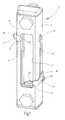
- Fig. 1
- eine gegenüber einer praktischen Ausführungsform leicht vergrößert gezeichnete perspektivische Schrägansicht eines Ausführungsbeispiels der erfindungsgemäßen Vorrichtung;
- Fig. 2
- eine annähernd in natürlicher Größe gezeichnete Seitenansicht des Ausführungsbeispiels von
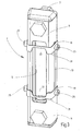
Fig. 1 ; - Fig. 3
- eine der
Fig. 1 ähnliche Darstellung eines zweiten Ausführungsbeispiels; - Fig. 4
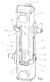
- eine den
Fig. 1 und3 ähnliche Darstellung eines dritten Ausführungsbeispiels; - Fig. 5 und 6
- vergrößert gezeichnete perspektivische Schrägansichten zweier Ausführungsformen von Markierungskörpern für Ausführungsbeispiele der erfindungsgemäßen Vorrichtung;
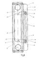
- Fig. 7 und 8
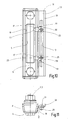
- eine perspektivische Schrägansicht bzw. Vorderansicht eines vierten Ausführungsbeispiels;
- Fig. 9 und 10
- eine perspektivische Schrägansicht bzw. Vorderansicht eines fünften Ausführungsbeispiels und
- Fig. 11
- eine Draufsicht des fünften Ausführungsbeispiels.
- Bei den in der Zeichnung dargestellten Ausführungsbeispielen weist die Vorrichtung einen unteren Fluidanschluss 1 und einen oberen Fluidanschluss 3 auf, die mit einem Steigrohr 5 an dessen unterem Ende bzw. oberem Ende in Fluidverbindung sind. Das Steigrohr 5 besteht aus einem durchsichtigen Werkstoff wie Plexiglas. Das Steigrohr 5 ist von einem Gehäuse 7 umgeben, das vorzugsweise aus einem Aluminiumwerkstoff gefertigt ist und eine Frontwand 9 sowie sich beidseits anschließende Seitenwände 11 aufweist. In der Frontwand 9 befindet sich eine Aussparung, die ein sich über einen Anzeigebereich erstreckendes Sichtfenster 10 bildet, durch das die Position des Fluidpegels und damit die Füllstandshöhe durch das durchsichtige Steigrohr 5 hindurch visuell beobachtbar ist.
- Beide Seitenwände 11 sind durch einen sich entlang der Hochachse erstreckenden Längsschlitz 13 durchbrochen, die endseitige Erweiterungen 15 aufweisen. Als Bestandteil einer Einstelleinrichtung für die Positionseinstellung von Markierungskörpern bilden die Längsschlitze 13 Führungsbahnen, längs deren Markierungskörper mittels einer Verschiebeeinrichtung stufenlos in Richtung der Hochachse lageveränderbar sind. Bei dem Ausführungsbeispiel von
Fig. 1 und2 ist an beiden Seitenwänden 11 jeweils ein Markierungskörper 17 angeordnet, wobei sich ein an der rechtsseitigen Seitenwand 11 befindlicher Markierungskörper 17 in der Nähe des unteren Endes des Sichtfensters 10, d.h. am unteren Ende des Anzeigebereichs, befindet, um ein Minimum der Füllstandshöhe zu markieren, und der andere Markierungskörper 17 sich im Bereich des oberen Endes des Anzeigebereichs befindet. Die Markierungskörper 17 sind vorzugsweise als Biegeteil aus einem Metallblech gefertigt und weisen, wie am besten ausFig. 5 zu ersehen ist, ein ebenflächiges Verbindungsteil 19 und ein davon abgebogenes, schmäleres Zeigerteil 21 auf. Das Verbindungsteil 19 ist, an der zugeordneten Seitenwand 11 anliegend, entlang des Längsschlitzes 13 in gewählte Anzeigepositionen verschiebbar. Das Zeigerteil 21 erstreckt sich, den Rand der Frontwand 9 übergreifend, bis in den Anzeigebereich des Sichtfensters 10 und endet in einer Zeigerspitze 23. - Als Bestandteil der Einstelleinrichtung für den jeweiligen Markierungskörper 17 weist eine Führungs- und Feststelleinrichtung eine Klemmschraube 25 auf, die eine Bohrung 27 im Verbindungsteil 19 durchgreift und mit einer T-Mutter (in der Zeichnung nicht sichtbar) zusammenwirkt, die an der Innenseite der jeweiligen Seitenwand 11 entlang des Längsschlitzes 13 geführt ist und den Markierungskörper 17 in der gewünschten Einstellposition sichert. Die Markierungskörper 17 können aus einem Metallblech gefertigt sein, jedoch auch aus Kunststoff hergestellt sein, der gegebenenfalls eingefärbt ist. Wenn es sich bei metallischem Werkstoff um ein Aluminiumblech handelt, kann dieses blank gelassen oder farbig eloxiert sein. Bei Herstellung aus einem Edelstahl kann eine farbliche Pulverbeschichtung vorgesehen sein. Durch farbige Unterscheidung, beispielsweise schwarz und rot, lassen sich kritische Füllstandshöhen augenfällig markieren, etwa Minima und Maxima.
- Das Ausführungsbeispiel gemäß
Fig. 3 entspricht dem zuvor beschriebenen Beispiel, abgesehen davon, dass Markierungskörper 31 in einer inFig. 6 gesondert dargestellten Bauform vorgesehen sind. Diese weisen zwei Verbindungsteile 19 für die Lageeinstellung und Festlegung an beiden Seitenwänden 11 des Gehäuses 7 auf. Als Zeigerteil ist eine schmale Leiste 13 vorgesehen, die die Verbindungsteile 19 miteinander verbindet und sich über den Anzeigebereich des Sichtfensters 10 erstreckt, sieheFig. 3 . Dadurch lassen sich die Grenzen eines zulässigen Bereichs von Füllstandshöhen besonders augenfällig markieren. - Das in
Fig. 4 gezeigte Ausführungsbeispiel verdeutlicht, dass sich die Erfindung auch in Verbindung mit einer Vorrichtung zur Füllstandskontrolle (FSK) verwirklichen lässt, wie sie in dem bereits erwähnten DokumentDE 10 2009 023 343 A1 offenbart ist, worauf Bezug genommen ist. Wie bei dieser Vorrichtung ist im Steigrohr 5 ein bewegbarer Schwimmerkörper 41 angeordnet, und es ist eine Sensoreinrichtung vorhanden, die die Position des Schwimmerkörpers 41 im Anzeigebereich des Steigrohres 5 erkennt und ein die Position kennzeichnendes Anzeigesignal liefert, das die Füllstandshöhe darstellt und benutzt werden kann, um Maßnahmen zur Korrektur oder Änderung des Füllstandes einzuleiten. Beim gezeigten Beispiel weist die Sensoreinrichtung Reed-Kontakte 43 auf, die elektrische Signale, ausgelöst durch magnetische Bestandteile des Schwimmerkörpers 41, erzeugen. Es versteht sich, dass anstelle von Reed-Kontakten 43 als Detektoren und Magneten als Auslöser geeignete andere Sensoreinrichtungen zur Positionserkennung angewendet werden könnten, beispielsweise photoelektrische Sensoreinrichtungen oder dergleichen.
Beim vorliegenden Ausführungsbeispiel sind die Reed-Kontakte 43 entlang der durch die Längsschlitze 13 der Seitenwände 11 gebildeten Führungsbahnen ebenso lageeinstellbar und lagesicherbar angeordnet wie die Markierungskörper 17. Die diesbezügliche Ausgestaltung der Reed-Kontakte 43 und die Art ihrer Führung und Lagesicherung in den Längsschlitzen 13 sind aus dem bereits erwähnten DokumentDE 10 2009 023 343 A1 an sich bekannt, so dass hierauf nicht näher eingegangen werden muss. - Das weitere Ausführungsbeispiel von
Fig. 7 und8 unterscheidet sich von den vorherigen Ausführungsbeispielen insofern, als die Führungsbahn 13 nicht unmittelbar an einer Seitenwand 11 ausgebildet ist, sondern an einer Abkantung 51 des Randes einer Seitenwand 11. Diese Abkantung 51, die durch eine Verlängerung der Seitenwand 11 gebildet ist, ist derart abgewinkelt, dass sie eine Ebene 53 bildet, die von der Frontwand 9 gegen die Fluidanschlüsse 1, 3 hin versetzt ist und in der die Führungsbahn 13 ausgebildet ist, entlang deren betreffende Markierungskörper 17 lageeinstellbar sind. Bei diesem Ausführungsbeispiel weist das Verbindungsteil 19 des jeweiligen Markierungskörpers 17 außer dem an dessen Seitenwand 11 anliegenden Abschnitt 55 einen davon abgewinkelten Abschnitt 57 auf, der an der Ebene 53 der Führungsbahn 13 anliegt. - Das weitere Beispiel von
Fig. 9 bis 11 unterscheidet sich vom Ausführungsbeispiel gemäßFig. 7 und8 insofern, als die Abkantung 51 der Seitenwand 11 einen sich neben der Führungsbahn 13 erstreckenden, weiter in Richtung gegen die Fluidanschlüsse 1, 3 hin abgewinkelten Rand 58 aufweist. Außerdem weist das Verbindungsteil 19 der Markierungskörper 17 einen Ansatz 59 auf, der gegenüber dem schmäleren Trägerteil 21 eine Verlängerung in Richtung der Führungsbahn 13 bildet und eine Fläche für das Aufbringen einer Füllstandsmarkierung 61 zur Verfügung stellt.
Claims (12)
- Vorrichtung zum Anzeigen der Höhe des Füllstandes von Fluiden, mit mindestens einem Fluidanschluss (1, 3) der in ein Steigrohr (5) mündet, dessen Wand zumindest innerhalb eines Anzeigebereichs (10) eine visuelle Beobachtung der Lage des Fluidpegels ermöglicht, dadurch gekennzeichnet, dass zumindest ein Markierungskörper (17, 31) vorhanden ist, der außerhalb des Steigrohres (5), jedoch in visueller Zuordnung zum Anzeigebereich (10), in einer gewählten Position festlegbar ist, die einer vorgegebenen, zu markierenden Füllstandshöhe entspricht.
- Vorrichtung nach Anspruch 1, dadurch gekennzeichnet, dass für den jeweiligen Markierungskörper (17, 31) eine Einstelleinrichtung (13, 25) vorhanden ist, mittels deren der Markierungskörper (17, 31) in gewählte Positionen einstellbar und in diesen festlegbar ist.
- Vorrichtung nach Anspruch 1 oder 2, dadurch gekennzeichnet, dass die Einstelleinrichtung durch eine Verschiebeeinrichtung (13, 25) gebildet ist, mittels deren der zumindest eine Markierungskörper (17, 31) in gewählte Einstellpositionen verschiebbar ist.
- Vorrichtung nach einem der vorstehenden Ansprüche, dadurch gekennzeichnet, dass sie ein das Steigrohr (5) zumindest teilweise umgebendes Gehäuse (7) aufweist und dass die Verschiebeeinrichtung mindestens eine am Gehäuse (7) befindliche, sich entlang zumindest eines Teils des Anzeigebereichs (10) erstreckende Führungsbahn (13) bildet, längs deren ein jeweiliger Markierungskörper (17, 31) zur Positionseinstellung verschiebbar und in ausgewählten Einstellpositionen festlegbar ist.
- Vorrichtung nach einem der vorstehenden Ansprüche, dadurch gekennzeichnet, dass das Gehäuse (7) eine Frontwand (9) mit zumindest einer als Sichtfenster (10) dienenden Unterbrechung und mindestens einer an die Frontwand (9) angrenzenden Seitenwand (11) aufweist, an der sich zumindest eine Führungsbahn (13) entlang der Hochachse des Gehäuses (7) erstreckt.
- Vorrichtung nach einem der vorstehenden Ansprüche, dadurch gekennzeichnet, dass eine Seitenwand (11) des Gehäuses (7) eine Abkantung (51) aufweist, die eine von der Frontwand (9) gegen die Fluidanschlüsse (1, 3) hin versetzte Ebene (53) bildet, an der die Führungsbahn (13) ausgebildet ist.
- Vorrichtung nach einem der vorstehenden Ansprüche, dadurch gekennzeichnet, dass die Abkantung (51) einen sich neben der Führungsbahn (13) erstreckenden, weiter in Richtung gegen die Fluidanschlüsse (1, 3) hin abgewinkelten Rand (58) aufweist.
- Vorrichtung nach einem der vorstehenden Ansprüche, dadurch gekennzeichnet, dass das Verbindungsteil (19) des jeweiligen Markierungskörpers (17) einen an der zugeordneten Seitenwand (11) anliegenden Abschnitt (55) und einen davon abgewinkelten, an der Ebene (53) der Führungsbahn (13) anliegenden Abschnitt (57) aufweist.
- Vorrichtung nach einem der vorstehenden Ansprüche, dadurch gekennzeichnet, dass der jeweilige Markierungskörper (17, 31) ein Verbindungsteil (19), das an der betreffenden Seitenwand (11) entlang der Führungsbahn (13) lageeinstell- und feststellbar ist, sowie ein vom Verbindungsteil (19) abgewinkeltes Zeigerteil (21, 33) aufweist, das sich, zumindest einen Teil der Frontwand (9) übergreifend, in den Bereich des Sichtfensters (10) erstreckt.
- Vorrichtung nach einem der vorstehenden Ansprüche, dadurch gekennzeichnet, dass das Gehäuse (7) zu beiden Seiten der Frontwand (9) eine Seitenwand (11) mit je einer Führungsbahn (13) für betreffende Markierungskörper (17, 31) aufweist.
- Vorrichtung nach einem der vorstehenden Ansprüche, dadurch gekennzeichnet, dass zumindest ein Markierungskörper (31) zwei Verbindungsteile (19) aufweist, deren einer entlang der Führungsbahn (13) der einen Seitenwand (11) und deren anderer entlang der Führungsbahn (13) der anderen Seitenwand (11) lageeinstell- und feststellbar ist, und dass die Verbindungsteile (19) über eine das Zeigerteil bildende Leiste (33) verbunden sind, die sich über das Sichtfenster (10) erstreckt.
- Vorrichtung nach einem der vorstehenden Ansprüche, dadurch gekennzeichnet, dass im Steigrohr (5) ein Schwimmerkörper (41) bewegbar geführt ist und dass zumindest eine dessen Lage erkennende Sensoreinrichtung (43) vorgesehen ist, die entlang der Führungsbahn (13) einer jeweiligen Seitenwand (11) lageeinstell- und feststellbar ist.
Applications Claiming Priority (1)
| Application Number | Priority Date | Filing Date | Title |
|---|---|---|---|
| DE102011121529A DE102011121529A1 (de) | 2011-12-16 | 2011-12-16 | Vorrichtung zum Anzeigen der Höhe des Füllstandes von Fluiden |
Publications (3)
| Publication Number | Publication Date |
|---|---|
| EP2604986A2 true EP2604986A2 (de) | 2013-06-19 |
| EP2604986A3 EP2604986A3 (de) | 2015-04-22 |
| EP2604986B1 EP2604986B1 (de) | 2021-08-11 |
Family
ID=47351348
Family Applications (1)
| Application Number | Title | Priority Date | Filing Date |
|---|---|---|---|
| EP12007984.3A Active EP2604986B1 (de) | 2011-12-16 | 2012-11-28 | Vorrichtung zum Anzeigen der Höhe des Füllstandes von Fluiden |
Country Status (2)
| Country | Link |
|---|---|
| EP (1) | EP2604986B1 (de) |
| DE (1) | DE102011121529A1 (de) |
Families Citing this family (1)
| Publication number | Priority date | Publication date | Assignee | Title |
|---|---|---|---|---|
| DE102021002969A1 (de) * | 2021-06-10 | 2022-12-15 | Hydac Accessories Gmbh | Vorrichtung zum Anzeigen eines Fluidniveaus |
Citations (1)
| Publication number | Priority date | Publication date | Assignee | Title |
|---|---|---|---|---|
| DE102009023343A1 (de) | 2009-05-29 | 2010-12-02 | Hydac Accessories Gmbh | Vorrichtung zum Anzeigen und/oder Kontrollieren von Fluiden |
Family Cites Families (8)
| Publication number | Priority date | Publication date | Assignee | Title |
|---|---|---|---|---|
| DE356843C (de) * | 1919-06-06 | 1922-07-31 | Herrmann Szweda | Wasserstandsanzeiger |
| GB794941A (en) * | 1955-06-11 | 1958-05-14 | Sartori Mario | Hydrostatic weight-checking device |
| DD66723A1 (de) * | 1967-11-09 | 1969-05-05 | Vorrichtung zur gewichtsmässigen Inhaltsbestimmung von Flüssigkeiten | |
| DE4120186A1 (de) * | 1991-06-19 | 1992-12-24 | Cramer Gmbh & Co Kg | Fuellstand-messvorrichtung fuer behaelter, insbesondere fuer gasflaschen |
| DE9416008U1 (de) * | 1994-10-05 | 1994-12-01 | Wu, Ting-Kuo, Shulin Chen, Teipeh | Montagestruktur für Niveau-Anzeigeeinrichtungen vom Bypass-Typ |
| EP1154245A1 (de) * | 2000-05-08 | 2001-11-14 | Merlin Design GmbH | Füllstandsanzeigevorrichtung für Behälter |
| US6988406B1 (en) * | 2004-10-25 | 2006-01-24 | Robert Mack | System and method of liquid level detection |
| DE102009007655A1 (de) * | 2009-02-05 | 2010-08-19 | Hydac Accessories Gmbh | Vorrichtung zum Anzeigen und/oder Kontrollieren von Fluiden |
-
2011
- 2011-12-16 DE DE102011121529A patent/DE102011121529A1/de not_active Withdrawn
-
2012
- 2012-11-28 EP EP12007984.3A patent/EP2604986B1/de active Active
Patent Citations (1)
| Publication number | Priority date | Publication date | Assignee | Title |
|---|---|---|---|---|
| DE102009023343A1 (de) | 2009-05-29 | 2010-12-02 | Hydac Accessories Gmbh | Vorrichtung zum Anzeigen und/oder Kontrollieren von Fluiden |
Also Published As
| Publication number | Publication date |
|---|---|
| EP2604986A3 (de) | 2015-04-22 |
| DE102011121529A1 (de) | 2013-06-20 |
| EP2604986B1 (de) | 2021-08-11 |
Similar Documents
| Publication | Publication Date | Title |
|---|---|---|
| EP2386825A2 (de) | Libelle für Wasserwaage | |
| EP0734305B1 (de) | Verfahren zum einstellen von reibahlen und dergleichen | |
| EP2256469B1 (de) | Vorrichtung zum Anzeigen und/oder Kontrollieren von Fluiden | |
| EP2604986B1 (de) | Vorrichtung zum Anzeigen der Höhe des Füllstandes von Fluiden | |
| DE102009007655A1 (de) | Vorrichtung zum Anzeigen und/oder Kontrollieren von Fluiden | |
| DE102010043739A1 (de) | Entlastungsanordnung eines Fensters, einer Tür oder dergleichen | |
| DE102011012689B4 (de) | Verfahren zur Bestimmung der Position eines Objekts in einem Bezugssystem | |
| DE19504929C2 (de) | Verfahren und Gerät zur Einmessung von Randfliesen beim Fliesenlegen | |
| DE202014105219U1 (de) | Erdungsschienenvorrichtung | |
| EP3333554B1 (de) | Vorrichtung zum anzeigen und/oder kontrollieren von fluidzuständen | |
| DE102017111207B3 (de) | Vorrichtung zur Dosierung von Infusionsbeuteln für medizinische Zwecke sowie Einrichtung zur Befüllung einer Mehrzahl von Leerbehältern | |
| EP3741264B1 (de) | Vorrichtung zum vorschub von waren | |
| EP2690017A2 (de) | Fixiervorrichtung für einen Ausstattungsgegenstand an einer Fixierschiene | |
| EP2816329B1 (de) | Vorrichtung zum Anzeigen und/oder Kontrollieren eines Fluidniveaus | |
| DE102018009534B4 (de) | Spannvorrichtung mit induktiver Abfrageeinheit | |
| DE102023132913B4 (de) | Ausziehbarer Zollstock | |
| DE4330988C2 (de) | Verfahren zum Einstellen von Reibahlen und dergleichen | |
| DE1658341C3 (de) | Vorrichtung zur Überwachung und/oder zur Aufnahme und Registrierung des Verlaufes eines Gleises, insbesondere für die Richtungsbestimmung beim Ausrichten gerader Gleisabschnitte | |
| DE1964470B2 (de) | Einrichtung zur erfassung von fuehrungsfehlern von beweglichen teilen insbesondere bei werkzeug oder messmaschinen | |
| DE102008036998A1 (de) | Entfernungsmesser und Verfahren zur Ermittlung der Entfernung von Messobjekten, insbesonere von Kampffahrzeugen | |
| DE102015215578B4 (de) | Magnetfeldsensor-Anordnung | |
| DE29601474U1 (de) | Nivellierungsvorrichtung | |
| DE1964470C (de) | Einrichtung zur Erfassung von Führungsfehlern von beweglichen Teilen, insbesondere bei Werkzeug- oder Meßmaschinen | |
| DE102006036102A1 (de) | Winkelgeber mit Montageöffnung | |
| DE202019104573U1 (de) | Schrankauszug |
Legal Events
| Date | Code | Title | Description |
|---|---|---|---|
| PUAI | Public reference made under article 153(3) epc to a published international application that has entered the european phase |
Free format text: ORIGINAL CODE: 0009012 |
|
| AK | Designated contracting states |
Kind code of ref document: A2 Designated state(s): AL AT BE BG CH CY CZ DE DK EE ES FI FR GB GR HR HU IE IS IT LI LT LU LV MC MK MT NL NO PL PT RO RS SE SI SK SM TR |
|
| AX | Request for extension of the european patent |
Extension state: BA ME |
|
| PUAL | Search report despatched |
Free format text: ORIGINAL CODE: 0009013 |
|
| AK | Designated contracting states |
Kind code of ref document: A3 Designated state(s): AL AT BE BG CH CY CZ DE DK EE ES FI FR GB GR HR HU IE IS IT LI LT LU LV MC MK MT NL NO PL PT RO RS SE SI SK SM TR |
|
| AX | Request for extension of the european patent |
Extension state: BA ME |
|
| RIC1 | Information provided on ipc code assigned before grant |
Ipc: G01F 23/74 20060101ALI20150317BHEP Ipc: G01F 23/70 20060101ALI20150317BHEP Ipc: G01F 23/02 20060101AFI20150317BHEP |
|
| 17P | Request for examination filed |
Effective date: 20150428 |
|
| RIN1 | Information on inventor provided before grant (corrected) |
Inventor name: JUERGEN, KAEFER |
|
| STAA | Information on the status of an ep patent application or granted ep patent |
Free format text: STATUS: EXAMINATION IS IN PROGRESS |
|
| 17Q | First examination report despatched |
Effective date: 20161031 |
|
| GRAP | Despatch of communication of intention to grant a patent |
Free format text: ORIGINAL CODE: EPIDOSNIGR1 |
|
| STAA | Information on the status of an ep patent application or granted ep patent |
Free format text: STATUS: GRANT OF PATENT IS INTENDED |
|
| INTG | Intention to grant announced |
Effective date: 20210504 |
|
| GRAS | Grant fee paid |
Free format text: ORIGINAL CODE: EPIDOSNIGR3 |
|
| GRAA | (expected) grant |
Free format text: ORIGINAL CODE: 0009210 |
|
| STAA | Information on the status of an ep patent application or granted ep patent |
Free format text: STATUS: THE PATENT HAS BEEN GRANTED |
|
| AK | Designated contracting states |
Kind code of ref document: B1 Designated state(s): AL AT BE BG CH CY CZ DE DK EE ES FI FR GB GR HR HU IE IS IT LI LT LU LV MC MK MT NL NO PL PT RO RS SE SI SK SM TR |
|
| REG | Reference to a national code |
Ref country code: GB Ref legal event code: FG4D Free format text: NOT ENGLISH |
|
| REG | Reference to a national code |
Ref country code: CH Ref legal event code: EP |
|
| REG | Reference to a national code |
Ref country code: DE Ref legal event code: R096 Ref document number: 502012016862 Country of ref document: DE |
|
| REG | Reference to a national code |
Ref country code: IE Ref legal event code: FG4D Free format text: LANGUAGE OF EP DOCUMENT: GERMAN Ref country code: AT Ref legal event code: REF Ref document number: 1419834 Country of ref document: AT Kind code of ref document: T Effective date: 20210915 |
|
| REG | Reference to a national code |
Ref country code: FI Ref legal event code: FGE |
|
| REG | Reference to a national code |
Ref country code: LT Ref legal event code: MG9D |
|
| REG | Reference to a national code |
Ref country code: NL Ref legal event code: MP Effective date: 20210811 |
|
| PG25 | Lapsed in a contracting state [announced via postgrant information from national office to epo] |
Ref country code: HR Free format text: LAPSE BECAUSE OF FAILURE TO SUBMIT A TRANSLATION OF THE DESCRIPTION OR TO PAY THE FEE WITHIN THE PRESCRIBED TIME-LIMIT Effective date: 20210811 Ref country code: SE Free format text: LAPSE BECAUSE OF FAILURE TO SUBMIT A TRANSLATION OF THE DESCRIPTION OR TO PAY THE FEE WITHIN THE PRESCRIBED TIME-LIMIT Effective date: 20210811 Ref country code: BG Free format text: LAPSE BECAUSE OF FAILURE TO SUBMIT A TRANSLATION OF THE DESCRIPTION OR TO PAY THE FEE WITHIN THE PRESCRIBED TIME-LIMIT Effective date: 20211111 Ref country code: LT Free format text: LAPSE BECAUSE OF FAILURE TO SUBMIT A TRANSLATION OF THE DESCRIPTION OR TO PAY THE FEE WITHIN THE PRESCRIBED TIME-LIMIT Effective date: 20210811 Ref country code: RS Free format text: LAPSE BECAUSE OF FAILURE TO SUBMIT A TRANSLATION OF THE DESCRIPTION OR TO PAY THE FEE WITHIN THE PRESCRIBED TIME-LIMIT Effective date: 20210811 Ref country code: PT Free format text: LAPSE BECAUSE OF FAILURE TO SUBMIT A TRANSLATION OF THE DESCRIPTION OR TO PAY THE FEE WITHIN THE PRESCRIBED TIME-LIMIT Effective date: 20211213 Ref country code: NO Free format text: LAPSE BECAUSE OF FAILURE TO SUBMIT A TRANSLATION OF THE DESCRIPTION OR TO PAY THE FEE WITHIN THE PRESCRIBED TIME-LIMIT Effective date: 20211111 Ref country code: ES Free format text: LAPSE BECAUSE OF FAILURE TO SUBMIT A TRANSLATION OF THE DESCRIPTION OR TO PAY THE FEE WITHIN THE PRESCRIBED TIME-LIMIT Effective date: 20210811 |
|
| PG25 | Lapsed in a contracting state [announced via postgrant information from national office to epo] |
Ref country code: PL Free format text: LAPSE BECAUSE OF FAILURE TO SUBMIT A TRANSLATION OF THE DESCRIPTION OR TO PAY THE FEE WITHIN THE PRESCRIBED TIME-LIMIT Effective date: 20210811 Ref country code: LV Free format text: LAPSE BECAUSE OF FAILURE TO SUBMIT A TRANSLATION OF THE DESCRIPTION OR TO PAY THE FEE WITHIN THE PRESCRIBED TIME-LIMIT Effective date: 20210811 Ref country code: GR Free format text: LAPSE BECAUSE OF FAILURE TO SUBMIT A TRANSLATION OF THE DESCRIPTION OR TO PAY THE FEE WITHIN THE PRESCRIBED TIME-LIMIT Effective date: 20211112 |
|
| PG25 | Lapsed in a contracting state [announced via postgrant information from national office to epo] |
Ref country code: NL Free format text: LAPSE BECAUSE OF FAILURE TO SUBMIT A TRANSLATION OF THE DESCRIPTION OR TO PAY THE FEE WITHIN THE PRESCRIBED TIME-LIMIT Effective date: 20210811 |
|
| PG25 | Lapsed in a contracting state [announced via postgrant information from national office to epo] |
Ref country code: DK Free format text: LAPSE BECAUSE OF FAILURE TO SUBMIT A TRANSLATION OF THE DESCRIPTION OR TO PAY THE FEE WITHIN THE PRESCRIBED TIME-LIMIT Effective date: 20210811 |
|
| REG | Reference to a national code |
Ref country code: DE Ref legal event code: R097 Ref document number: 502012016862 Country of ref document: DE |
|
| PG25 | Lapsed in a contracting state [announced via postgrant information from national office to epo] |
Ref country code: SM Free format text: LAPSE BECAUSE OF FAILURE TO SUBMIT A TRANSLATION OF THE DESCRIPTION OR TO PAY THE FEE WITHIN THE PRESCRIBED TIME-LIMIT Effective date: 20210811 Ref country code: SK Free format text: LAPSE BECAUSE OF FAILURE TO SUBMIT A TRANSLATION OF THE DESCRIPTION OR TO PAY THE FEE WITHIN THE PRESCRIBED TIME-LIMIT Effective date: 20210811 Ref country code: RO Free format text: LAPSE BECAUSE OF FAILURE TO SUBMIT A TRANSLATION OF THE DESCRIPTION OR TO PAY THE FEE WITHIN THE PRESCRIBED TIME-LIMIT Effective date: 20210811 Ref country code: EE Free format text: LAPSE BECAUSE OF FAILURE TO SUBMIT A TRANSLATION OF THE DESCRIPTION OR TO PAY THE FEE WITHIN THE PRESCRIBED TIME-LIMIT Effective date: 20210811 Ref country code: CZ Free format text: LAPSE BECAUSE OF FAILURE TO SUBMIT A TRANSLATION OF THE DESCRIPTION OR TO PAY THE FEE WITHIN THE PRESCRIBED TIME-LIMIT Effective date: 20210811 Ref country code: AL Free format text: LAPSE BECAUSE OF FAILURE TO SUBMIT A TRANSLATION OF THE DESCRIPTION OR TO PAY THE FEE WITHIN THE PRESCRIBED TIME-LIMIT Effective date: 20210811 |
|
| PLBE | No opposition filed within time limit |
Free format text: ORIGINAL CODE: 0009261 |
|
| STAA | Information on the status of an ep patent application or granted ep patent |
Free format text: STATUS: NO OPPOSITION FILED WITHIN TIME LIMIT |
|
| PG25 | Lapsed in a contracting state [announced via postgrant information from national office to epo] |
Ref country code: MC Free format text: LAPSE BECAUSE OF FAILURE TO SUBMIT A TRANSLATION OF THE DESCRIPTION OR TO PAY THE FEE WITHIN THE PRESCRIBED TIME-LIMIT Effective date: 20210811 |
|
| REG | Reference to a national code |
Ref country code: CH Ref legal event code: PL |
|
| 26N | No opposition filed |
Effective date: 20220512 |
|
| GBPC | Gb: european patent ceased through non-payment of renewal fee |
Effective date: 20211128 |
|
| PG25 | Lapsed in a contracting state [announced via postgrant information from national office to epo] |
Ref country code: LU Free format text: LAPSE BECAUSE OF NON-PAYMENT OF DUE FEES Effective date: 20211128 Ref country code: IT Free format text: LAPSE BECAUSE OF FAILURE TO SUBMIT A TRANSLATION OF THE DESCRIPTION OR TO PAY THE FEE WITHIN THE PRESCRIBED TIME-LIMIT Effective date: 20210811 Ref country code: BE Free format text: LAPSE BECAUSE OF NON-PAYMENT OF DUE FEES Effective date: 20211130 |
|
| REG | Reference to a national code |
Ref country code: BE Ref legal event code: MM Effective date: 20211130 |
|
| PG25 | Lapsed in a contracting state [announced via postgrant information from national office to epo] |
Ref country code: SI Free format text: LAPSE BECAUSE OF FAILURE TO SUBMIT A TRANSLATION OF THE DESCRIPTION OR TO PAY THE FEE WITHIN THE PRESCRIBED TIME-LIMIT Effective date: 20210811 Ref country code: LI Free format text: LAPSE BECAUSE OF NON-PAYMENT OF DUE FEES Effective date: 20211130 Ref country code: CH Free format text: LAPSE BECAUSE OF NON-PAYMENT OF DUE FEES Effective date: 20211130 |
|
| PG25 | Lapsed in a contracting state [announced via postgrant information from national office to epo] |
Ref country code: IE Free format text: LAPSE BECAUSE OF NON-PAYMENT OF DUE FEES Effective date: 20211128 Ref country code: GB Free format text: LAPSE BECAUSE OF NON-PAYMENT OF DUE FEES Effective date: 20211128 |
|
| REG | Reference to a national code |
Ref country code: AT Ref legal event code: MM01 Ref document number: 1419834 Country of ref document: AT Kind code of ref document: T Effective date: 20211128 |
|
| PG25 | Lapsed in a contracting state [announced via postgrant information from national office to epo] |
Ref country code: AT Free format text: LAPSE BECAUSE OF NON-PAYMENT OF DUE FEES Effective date: 20211128 |
|
| PG25 | Lapsed in a contracting state [announced via postgrant information from national office to epo] |
Ref country code: HU Free format text: LAPSE BECAUSE OF FAILURE TO SUBMIT A TRANSLATION OF THE DESCRIPTION OR TO PAY THE FEE WITHIN THE PRESCRIBED TIME-LIMIT; INVALID AB INITIO Effective date: 20121128 Ref country code: CY Free format text: LAPSE BECAUSE OF FAILURE TO SUBMIT A TRANSLATION OF THE DESCRIPTION OR TO PAY THE FEE WITHIN THE PRESCRIBED TIME-LIMIT Effective date: 20210811 |
|
| PGFP | Annual fee paid to national office [announced via postgrant information from national office to epo] |
Ref country code: FI Payment date: 20230908 Year of fee payment: 12 |
|
| PGFP | Annual fee paid to national office [announced via postgrant information from national office to epo] |
Ref country code: FR Payment date: 20231006 Year of fee payment: 12 Ref country code: DE Payment date: 20231130 Year of fee payment: 12 |
|
| PG25 | Lapsed in a contracting state [announced via postgrant information from national office to epo] |
Ref country code: MK Free format text: LAPSE BECAUSE OF FAILURE TO SUBMIT A TRANSLATION OF THE DESCRIPTION OR TO PAY THE FEE WITHIN THE PRESCRIBED TIME-LIMIT Effective date: 20210811 |
|
| PG25 | Lapsed in a contracting state [announced via postgrant information from national office to epo] |
Ref country code: TR Free format text: LAPSE BECAUSE OF FAILURE TO SUBMIT A TRANSLATION OF THE DESCRIPTION OR TO PAY THE FEE WITHIN THE PRESCRIBED TIME-LIMIT Effective date: 20210811 |
|
| PG25 | Lapsed in a contracting state [announced via postgrant information from national office to epo] |
Ref country code: MT Free format text: LAPSE BECAUSE OF FAILURE TO SUBMIT A TRANSLATION OF THE DESCRIPTION OR TO PAY THE FEE WITHIN THE PRESCRIBED TIME-LIMIT Effective date: 20210811 |
|
| REG | Reference to a national code |
Ref country code: DE Ref legal event code: R119 Ref document number: 502012016862 Country of ref document: DE |
|
| PG25 | Lapsed in a contracting state [announced via postgrant information from national office to epo] |
Ref country code: FI Free format text: LAPSE BECAUSE OF NON-PAYMENT OF DUE FEES Effective date: 20241128 |
|
| PG25 | Lapsed in a contracting state [announced via postgrant information from national office to epo] |
Ref country code: DE Free format text: LAPSE BECAUSE OF NON-PAYMENT OF DUE FEES Effective date: 20250603 |
|
| PG25 | Lapsed in a contracting state [announced via postgrant information from national office to epo] |
Ref country code: FR Free format text: LAPSE BECAUSE OF NON-PAYMENT OF DUE FEES Effective date: 20241130 |