EP2604992A2 - Verfahren zur Charakterisierung optischer Eigenschaften einer optischen Faser - Google Patents
Verfahren zur Charakterisierung optischer Eigenschaften einer optischen Faser Download PDFInfo
- Publication number
- EP2604992A2 EP2604992A2 EP12192700.8A EP12192700A EP2604992A2 EP 2604992 A2 EP2604992 A2 EP 2604992A2 EP 12192700 A EP12192700 A EP 12192700A EP 2604992 A2 EP2604992 A2 EP 2604992A2
- Authority
- EP
- European Patent Office
- Prior art keywords
- optical
- fiber
- rrel
- otdr
- fibers
- Prior art date
- Legal status (The legal status is an assumption and is not a legal conclusion. Google has not performed a legal analysis and makes no representation as to the accuracy of the status listed.)
- Withdrawn
Links
- 238000000034 method Methods 0.000 title claims abstract description 79
- 239000013307 optical fiber Substances 0.000 title claims abstract description 49
- 230000003287 optical effect Effects 0.000 title claims abstract description 43
- 238000012512 characterization method Methods 0.000 title 1
- 239000000835 fiber Substances 0.000 claims abstract description 59
- 238000005259 measurement Methods 0.000 claims abstract description 21
- 238000012360 testing method Methods 0.000 claims abstract description 14
- 230000008878 coupling Effects 0.000 claims description 9
- 238000010168 coupling process Methods 0.000 claims description 9
- 238000005859 coupling reaction Methods 0.000 claims description 9
- 238000011088 calibration curve Methods 0.000 claims description 8
- 230000002457 bidirectional effect Effects 0.000 claims description 3
- 238000012797 qualification Methods 0.000 abstract 1
- 239000003550 marker Substances 0.000 description 4
- 238000000691 measurement method Methods 0.000 description 4
- 230000008569 process Effects 0.000 description 4
- 238000010998 test method Methods 0.000 description 4
- 230000005540 biological transmission Effects 0.000 description 3
- 238000013461 design Methods 0.000 description 3
- 238000002474 experimental method Methods 0.000 description 3
- 230000035945 sensitivity Effects 0.000 description 3
- 230000008859 change Effects 0.000 description 2
- 238000005253 cladding Methods 0.000 description 2
- 230000006872 improvement Effects 0.000 description 2
- 238000010561 standard procedure Methods 0.000 description 2
- 238000012935 Averaging Methods 0.000 description 1
- 238000004891 communication Methods 0.000 description 1
- 230000007423 decrease Effects 0.000 description 1
- 230000001419 dependent effect Effects 0.000 description 1
- 238000009826 distribution Methods 0.000 description 1
- 230000000694 effects Effects 0.000 description 1
- 230000001747 exhibiting effect Effects 0.000 description 1
- 230000006355 external stress Effects 0.000 description 1
- 239000003365 glass fiber Substances 0.000 description 1
- 230000000977 initiatory effect Effects 0.000 description 1
- 238000011835 investigation Methods 0.000 description 1
- 238000004519 manufacturing process Methods 0.000 description 1
- 239000005304 optical glass Substances 0.000 description 1
- 238000005457 optimization Methods 0.000 description 1
- 230000001902 propagating effect Effects 0.000 description 1
- 238000003892 spreading Methods 0.000 description 1
- 230000007480 spreading Effects 0.000 description 1
- 230000001360 synchronised effect Effects 0.000 description 1
Images


Classifications
-
- G—PHYSICS
- G01—MEASURING; TESTING
- G01M—TESTING STATIC OR DYNAMIC BALANCE OF MACHINES OR STRUCTURES; TESTING OF STRUCTURES OR APPARATUS, NOT OTHERWISE PROVIDED FOR
- G01M11/00—Testing of optical apparatus; Testing structures by optical methods not otherwise provided for
- G01M11/30—Testing of optical devices, constituted by fibre optics or optical waveguides
- G01M11/31—Testing of optical devices, constituted by fibre optics or optical waveguides with a light emitter and a light receiver being disposed at the same side of a fibre or waveguide end-face, e.g. reflectometers
-
- G—PHYSICS
- G01—MEASURING; TESTING
- G01N—INVESTIGATING OR ANALYSING MATERIALS BY DETERMINING THEIR CHEMICAL OR PHYSICAL PROPERTIES
- G01N21/00—Investigating or analysing materials by the use of optical means, i.e. using sub-millimetre waves, infrared, visible or ultraviolet light
- G01N21/84—Systems specially adapted for particular applications
Definitions
- the present invention relates to a method for the determination of optical properties of an optical fiber. Furthermore, the present invention relates to the use of a specific method for the determination of one or more optical properties of an optical fiber. Additionally, the present invention relates to a method for selecting optical fibers for a specific configuration, especially the selection of Multi Mode optical fibers (MMF) to be applied in so called ribbon cables, or configurations where MMF are required that are less sensitive to attenuation increase caused by bends in the fibers.
- MMF Multi Mode optical fibers
- JP2008203184 relates to a method, an apparatus and a program for evaluating a characteristic of an optical fiber obtained by a bidirectional OTDR measurement from both ends of the transmission path.
- JP3120437 relates to a method for measuring strain from an optical waveguide in which reference optical fiber and a test optical fiber are connected to each other and an OTDR measuring instrument is connected to the side of the fiber.
- the strain of the fiber is found by specific arithmetic from the shift and the measured Brillouin frequency shift of the fiber (t).
- JP11287741 relates to a method for measuring the maximum theoretical numerical aperture of an optical fiber.
- Optical fibre ribbons are used for data communication applications in which a high data speed is used.
- the effective high data speed is obtained by parallel transmission on a plurality of glass fibres, using a correspondingly lower speed.
- a delay time occurs for each optical fibre, which may lead to differences in the signal arrival times between respective fibre channels.
- Skew is the maximum difference in signal propagation time between the channels in the optical fibre ribbon. Skew is an important factor in determining the maximum speed of synchronous parallel data transmission.
- the ribbon skew is expressed in ps/m being the maximum delay time difference per unit of length between the various fibers from the ribbon.
- MMF Multi Mode Optical Fiber
- Maximum value for Ge-doped MMF is in the order of 15 ps/m.
- a second order impact on delay time differences is in the wavelength variation of the optical signal source which has a maximum value in the order of 2 ps/m if the total 840 to 860 nm wavelength range is applied.
- DMD differential mode delay
- NA eff effective NA
- the main causes for the deviation are supposed to be measuring inaccuracy and process tolerances.
- the NA eff value is measured applying the so-called Far Field Scanning method in which a scan is made of the far field of a 2 m fiber sample illuminated by an 850 nm LED with the appropriate launching conditions.
- the main process influences that cause the intrinsic variation in NA eff are in i) the Ge dope concentration variation at the core centre line and ii) the drawing induces variations in NA eff value, that are assumed to be small.
- the NA values of a set of MMF used in an optical fiber ribbon is thus an indicator for the skew of such optical fiber ribbon.
- the NA values of a large batch of MMF can thus be used to select MMF for an optical fiber ribbon with low skew.
- the NA value of an MMF is also an indicator of the macrobend sensitivity of an MMF.
- Macrobend sensitivity is defined as the induced attenuation, or loss in dB when a fiber is bended to a certain bend radius over a certain number of turns.
- MMF with low macrobend sensitivity are preferably used in situations where the MMF is bend in low radii, or where the MMF is exhibiting external stresses such as in an optical fiber ribbon.
- optical fiber properties delay time also called 'time of flight'
- 'time of flight' that can be used to determine skew for a group of fibers and Macrobend induced attenuation
- specific measurement equipment is required with the need for extensive operator handling.
- NA, or NA eff requires specific measurement equipment and extensive operator handling.
- An object of the present invention is to provide a reliable and reproducible method for the determination of one or more optical properties of an optical fiber.
- Another object of the present invention is to provide a method for the determination of one or more optical properties of an optical fiber in which method extensive manual operator handling is prevented.
- Another object of the present invention is to provide a method for the determination of one or more optical properties of an optical fiber in which method the number of measurement equipments is minimized.
- Another object of the present invention is to provide an accurate NA measurement for the purpose of fiber selection on NA value.
- Another object of the present invention is to provide a method allowing for selection of MMF from stock to be applied in special ribbon cables with low skew requirements without the need to use expensive dedicated equipment.
- the present inventors thus found a method for the determination of one or more optical properties of an optical fiber, said method comprises according to the present invention the flowing steps:
- steps v) and vi) can be repeated for determining a value of the optical property for a larger batch of optical fibers.
- the aforementioned method has resulted in a method which is reproducible and low costs, compared to the current measurement methods.
- the number of measurement setups is drastically reduced, compared to the standard method for measuring these optical properties.
- the present method it is preferred to use the OTDR measurement for determining one or more fiber optical properties.
- the present method relates thus to the determination of R rel , (Relative Backscatter Coefficient) from an OTDR backscatter trace, and to use this R rel together with a calibration curve to assign fiber properties to a fiber under test.
- These properties are NA (Numerical Aperture), delay time, and Macrobend induced attenuation. Up till now determination of these parameters requires specific measurement setups (being not OTDR) with extensive operator handling.
- the optical property is preferably chosen from the group of NA, delay time, Macrobend induced attenuation, or combinations thereof.
- the determination of the optical property Macrobend induced attenuation according to step ii) is carried out by applying bends having a specific bend radius in an optical fiber and subsequently measuring the Macrobend induced attenuation of the light signal.
- the determination of the optical property delay time according step ii) is carried out by a Time Of Flight (TOF) measurement of a laser pulse travelling through the fiber with exact known length.
- TOF measurement is done by using a digital signal analyzer with calibrated delay-line.
- the determination of the optical property NA according step ii) is carried out by a Far Field Scanning method.
- the optical property is NA and the delay time and/or Macrobend induced attenuation are calculated using mathematical formulas based on the value determined for NA.
- the present method may also be used to determine the fiber skew of a group of MMF by using the delay times for said group of MMF, obtained by the present method.
- ⁇ the core contrast
- NA is proportional with NA 2 .
- NAeff 0.95*NAtheor.
- the test method itself is equivalent to measuring the splice or coupling loss between two fibers applying the bi-directional OTDR method, i.e. measuring the discontinuity at a splice or coupling point from two directions.
- ⁇ is the direction dependent splice or coupling loss
- R REF and R FUT represent the backscattering coefficients of the reference MMF (REF) and the MMF under test (FUT), respectively.
- the backscattering coefficient is expressed in dB.
- the repeatability of the test method is determined by re-measuring a fibre-to-fibre splicing or coupling 10 times. After each measurement the full procedure of cleaving, optimization, splicing and measurement of the discontinuities from two sides is repeated. For measuring the discontinuity on the applied OTDR set-up, a 100 m marker distance was used and the measured loss was compensated for the fiber loss over this marker distance (fixed value of 0.051 dB;). All measurements were done at 1300 nm.
- the present inventors found that a significant improvement can be achieved by applying the standard algorithm of fitting both backscatter curves with a linear curve, extrapolating these curves to the splicing or coupling position and determining the discontinuity value from the cross section.
- the present invention is thus related to a method of determining the backscattering coefficient from bidirectional measurement of the splice or coupling loss between a reference MMF (REF) and the MMF under test (FUT).
- steps iv) and vi) are carried out by using an optical time domain reflectometer (OTDR) based method.
- OTDR optical time domain reflectometer
- the present invention relates furthermore to the use of an optical time domain reflectometer (OTDR) based method for determining the Macrobend induced attenuation and/or time delay by measuring the relative backscatter coefficient (Rrel) of said optical fiber.
- OTDR optical time domain reflectometer
- the present invention relates to the use of an optical time domain reflectometer (OTDR) based method for determining the NA by measuring the relative backscatter coefficient (Rrel) of said optical fiber.
- OTDR optical time domain reflectometer
- the present invention relates thus to a method for determining the NA by measuring the relative backscatter coefficient (Rrel) of an optical fiber by using the afore mentioned discussed optical time domain reflectometer (OTDR) based method.
- the present invention relates thus to a method for determining the Macrobend induced attenuation by measuring the relative backscatter coefficient (Rrel) of an optical fiber by using the afore mentioned discussed optical time domain reflectometer (OTDR) based method.
- the present invention relates thus to a method for determining the time delay by measuring the relative backscatter coefficient (Rrel) of an optical fiber by using the afore mentioned discussed optical time domain reflectometer (OTDR) based method.
- the present invention relates thus to a method for determining the skew by measuring the relative backscatter coefficient (Rrel) of a group of optical fibers by using the afore mentioned discussed optical time domain reflectometer (OTDR) based method.
- Rel relative backscatter coefficient
- Figure 1 shows a bi-directional OTDR test set-up for determining the relative backscatter coefficient Rrel of the MMF under test.
- the OTDR trace (3) of the used launching Single Mode Fiber (SMF) and the MMF under test (2) shows a rather high coupling loss between these fibers, i.e. in the order of 2 dB, which did not deteriorate the dynamic range of the test method noticeably, however.
- SMF Single Mode Fiber
- the REF fiber (6) and FUTs fibers (5) were coupled by making a splice (7).
- the launching SMF's were coupled to the MMF's by a mechanical coupler (4a, 4b).
- Average splice loss (1) between the FUT and REF was 0.023 dB over more than 50 splices.
- the average of the difference in backscatter coefficients between the two spliced fibers was 0.016 dB for the chosen fiber samples whereas the variance was 0.009 dB.
- Figure 2 shows the measured relation between NA eff (measured with existing NA measurement technique) and R rel , the Relative Backscatter Coefficient measured with the method according to the present invention.
- Figure 2 shows two lines representing different fiber designs (2003 and 2006).
- the fitted line over the 2006 FUTs shows a linear relation between both parameters, i.e. the Na eff on the horizontal axis and the R rel on the vertical axis.
- the fitted line is the calibration curve.
- the error bars show the wider spread over the NA eff values compared to the R rel values. This justifies the use of the present method by measuring R rel by using OTDR and subsequently computing NA eff from the calibration curve.
- the position of the fitted line depends on both the design of the Reference fiber and the FUTs. This means the preference of using the same Reference fiber, and, in case the design of the FUT has changed, the calibration curve must be reconstructed, i.e. the relation between R rel , and Na eff must be re-measured.
- the result of the present method is that once the relation between R rel , and NA eff is known, it is possible to measure R rel , and use this parameter to assign NA eff to the fiber under test.
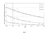
- a number of nine multimode Fibers are bended by applying two turns over three different bend radii (5, 7.5 and 15 mm).
- the Macrobend induced attenuation [dB] is measured by an existing macrobend measurement technique. This standard technique involves severe operator handling as the fiber must be carefully bended, and the launched light must fulfill precise launching conditions. In a subsequent step these fibers are measured on R rel with the present method, in which the OTDR method is preferably used, as described above. The results have been disclosed in Figure 3 .
- Figure 3 clearly shows an increasing Macrobend induced attenuation when the R rel value decreases.
- the R rel value serves as an indicator for determining the Macrobend induced attenuation of an optical fiber.
- Examples 1-2 clearly show that the present optical time domain reflectometer (OTDR) based method can be used for i) determining the NA eff of an optical fiber and ii) determining the Macrobend induced attenuation, both by measuring the relative backscatter coefficient (Rrel).
- OTDR optical time domain reflectometer
Landscapes
- Physics & Mathematics (AREA)
- General Physics & Mathematics (AREA)
- Chemical & Material Sciences (AREA)
- Analytical Chemistry (AREA)
- Optics & Photonics (AREA)
- General Health & Medical Sciences (AREA)
- Biochemistry (AREA)
- Life Sciences & Earth Sciences (AREA)
- Immunology (AREA)
- Pathology (AREA)
- Health & Medical Sciences (AREA)
- Testing Of Optical Devices Or Fibers (AREA)
- Manufacture, Treatment Of Glass Fibers (AREA)
Applications Claiming Priority (1)
| Application Number | Priority Date | Filing Date | Title |
|---|---|---|---|
| NL2007976A NL2007976C2 (en) | 2011-12-15 | 2011-12-15 | A method for the characterization of optical properties of an optical fiber. |
Publications (2)
| Publication Number | Publication Date |
|---|---|
| EP2604992A2 true EP2604992A2 (de) | 2013-06-19 |
| EP2604992A3 EP2604992A3 (de) | 2017-10-04 |
Family
ID=47215416
Family Applications (1)
| Application Number | Title | Priority Date | Filing Date |
|---|---|---|---|
| EP12192700.8A Withdrawn EP2604992A3 (de) | 2011-12-15 | 2012-11-15 | Verfahren zur Charakterisierung optischer Eigenschaften einer optischen Faser |
Country Status (4)
| Country | Link |
|---|---|
| US (1) | US8547541B2 (de) |
| EP (1) | EP2604992A3 (de) |
| CN (1) | CN103162938B (de) |
| NL (1) | NL2007976C2 (de) |
Families Citing this family (14)
| Publication number | Priority date | Publication date | Assignee | Title |
|---|---|---|---|---|
| US9134197B2 (en) | 2013-01-15 | 2015-09-15 | Exfo Inc. | Bi-directional multi-pulsewidth optical time-domain reflectometer |
| US9228922B1 (en) * | 2013-10-31 | 2016-01-05 | The United States Of America As Represented By The Secretary Of The Navy | Optical time domain reflectometer calibration standard |
| US9709460B2 (en) * | 2013-12-20 | 2017-07-18 | Exfo Inc. | Method and system for measuring an optical loss value of an optical fiber link |
| CN103808492B (zh) * | 2014-02-13 | 2016-01-27 | 大豪信息技术(威海)有限公司 | 一种otdr采集数据的曲线显示方法 |
| CN104089756B (zh) * | 2014-06-11 | 2017-05-24 | 清华大学 | 一种光纤状态检测方法及系统 |
| WO2016034913A1 (en) * | 2014-09-03 | 2016-03-10 | Draka Comteq Bv | Method for qualifying the effective modal bandwidth of a multimode fiber over a wide wavelength range from a single wavelength dmd measurement and method for selecting a high effective modal bandwidth multimode fiber from a batch of multimode fibers |
| US10168246B2 (en) * | 2015-11-24 | 2019-01-01 | Corning Incorporated | Methods of selecting optical fibers that meet bandwidth requirements at different wavelengths |
| US10382124B2 (en) * | 2015-12-07 | 2019-08-13 | Draka Comteq B.V. | Method for selecting wide-band multimode fibers from a single wavelength characterization |
| SG11201901980QA (en) * | 2016-09-08 | 2019-04-29 | Mark Andrew Englund | Method and system for distributed acoustic sensing |
| CN108168848B (zh) * | 2018-02-13 | 2024-05-03 | 南光高科(厦门)激光科技有限公司 | 一种多模光纤测试装置 |
| CN108872154B (zh) * | 2018-05-25 | 2021-01-01 | 中国科学院上海光学精密机械研究所 | 无包层光纤空间角分辨激光散射损耗的测量装置和方法 |
| US10914655B2 (en) * | 2018-08-28 | 2021-02-09 | Viavi Solutions Inc. | Optical time-domain reflectometer device including multiple and bi-directional optical testing for fiber analysis |
| EP3996295A1 (de) | 2020-11-04 | 2022-05-11 | Viavi Solutions Inc. | Auf einem bidirektionalen optischen hochgeschwindigkeitszeitbereichsreflektometer (otdr) basiertes prüfen einer zu prüfenden vorrichtung |
| US11431408B2 (en) | 2020-11-04 | 2022-08-30 | Viavi Solutions Inc. | High speed bidirectional optical time-domain reflectometer (OTDR)-based testing of device under test |
Citations (3)
| Publication number | Priority date | Publication date | Assignee | Title |
|---|---|---|---|---|
| JPH11287741A (ja) | 1998-03-31 | 1999-10-19 | Furukawa Electric Co Ltd:The | アパーチャーを用いた光ファイバ開口数の測定方法 |
| JP3120437B2 (ja) | 1990-07-04 | 2000-12-25 | 三菱マテリアル株式会社 | スローアウエイチツプ |
| JP2008203184A (ja) | 2007-02-22 | 2008-09-04 | Nippon Telegr & Teleph Corp <Ntt> | 光ファイバの特性評価方法および装置ならびにプログラム |
Family Cites Families (10)
| Publication number | Priority date | Publication date | Assignee | Title |
|---|---|---|---|---|
| JPS55152433A (en) * | 1979-05-17 | 1980-11-27 | Kokusai Denshin Denwa Co Ltd <Kdd> | Light loss measuring instrument |
| US4838690A (en) * | 1988-04-12 | 1989-06-13 | Sumitomo Electric Fiber Optics Corporation | Simultaneous bi-directional optical time domain reflectometry method |
| JP2840682B2 (ja) | 1989-10-03 | 1998-12-24 | 日本電信電話株式会社 | 光導波路の歪または温度の測定方法および装置 |
| US5130535A (en) * | 1990-10-10 | 1992-07-14 | At&T Bell Laboratories | Methods of and apparatus for measuring bending loss along a length of optical fiber |
| WO2000062033A1 (en) * | 1999-04-09 | 2000-10-19 | Corning Incorporated | Apparatus for measuring the properties of an optical fiber |
| US6519026B1 (en) * | 1999-08-06 | 2003-02-11 | Lucent Technologies Inc. | Optical time-domain reflectometer (OTDR) |
| US7003202B2 (en) * | 2003-04-28 | 2006-02-21 | The Furukawa Electric Co., Ltd. | Method and system for measuring the wavelength dispersion and nonlinear coefficient of an optical fiber, method of manufacturing optical fibers, method of measuring wavelength-dispersion distribution, method of compensating for measurement errors, and method of specifying conditions of measurement |
| JPWO2005071381A1 (ja) * | 2004-01-27 | 2007-09-06 | 株式会社フジクラ | マルチモード光ファイバの測定方法 |
| CN1300956C (zh) * | 2004-04-06 | 2007-02-14 | 华为技术有限公司 | 光时域反射仪的光模块及光时域反射仪以及光纤测试方法 |
| CN101793600B (zh) * | 2010-04-15 | 2011-04-20 | 上海交通大学 | 光纤传输损耗系数测量装置及测量方法 |
-
2011
- 2011-12-15 NL NL2007976A patent/NL2007976C2/en active
-
2012
- 2012-11-15 EP EP12192700.8A patent/EP2604992A3/de not_active Withdrawn
- 2012-11-29 US US13/689,061 patent/US8547541B2/en active Active
- 2012-12-17 CN CN201210548574.3A patent/CN103162938B/zh active Active
Patent Citations (3)
| Publication number | Priority date | Publication date | Assignee | Title |
|---|---|---|---|---|
| JP3120437B2 (ja) | 1990-07-04 | 2000-12-25 | 三菱マテリアル株式会社 | スローアウエイチツプ |
| JPH11287741A (ja) | 1998-03-31 | 1999-10-19 | Furukawa Electric Co Ltd:The | アパーチャーを用いた光ファイバ開口数の測定方法 |
| JP2008203184A (ja) | 2007-02-22 | 2008-09-04 | Nippon Telegr & Teleph Corp <Ntt> | 光ファイバの特性評価方法および装置ならびにプログラム |
Non-Patent Citations (2)
| Title |
|---|
| "Experimental Investigation of Variation of Backscattered Power Level with Numerical Aperture in Multimode Optical Fibers", ELECTRONICS LETTERS, vol. 18, 1982, pages 130 - 132 |
| P.MATTHIJSSE; C.M DE BLOK: "Field measurement of splice loss applying the backscattering method", ELECTRONICS LETTERS, vol. 15, no. 24, 1979, pages 795 - 6 |
Also Published As
| Publication number | Publication date |
|---|---|
| CN103162938B (zh) | 2016-08-03 |
| US20130155391A1 (en) | 2013-06-20 |
| CN103162938A (zh) | 2013-06-19 |
| EP2604992A3 (de) | 2017-10-04 |
| NL2007976C2 (en) | 2013-06-18 |
| US8547541B2 (en) | 2013-10-01 |
Similar Documents
| Publication | Publication Date | Title |
|---|---|---|
| US8547541B2 (en) | Method for the characterization of optical properties of an optical fiber | |
| US4838690A (en) | Simultaneous bi-directional optical time domain reflectometry method | |
| CN105865752B (zh) | 采用分布式偏振串扰分析仪全面评判保偏光纤特性的方法和装置 | |
| US9562827B2 (en) | Measuring method of longitudinal distribution of bending loss of optical fiber, measuring method of longitudinal distribution of actual bending loss value of optical fiber, test method of optical line, manufacturing method of optical fiber cable, manufacturing method of optical fiber cord, and manufacturing method of optical fiber | |
| JP5948368B2 (ja) | 光ファイバの特性評価方法 | |
| EP2567207B1 (de) | Verfahren zur überprüfung der korrekten installation eines biegeunempfindlichen optischen kabels und für dieses verfahren geeignetes optisches kabel | |
| US11156529B2 (en) | Nonlinearity measuring method and nonlinearity measuring device | |
| US12372714B2 (en) | Optical channel bandwidth analyzer | |
| JP2005518564A (ja) | ブロードバンドアクセス用ファイバ及びその製造方法 | |
| Wang et al. | Evaluation of splicing quality in few-mode optical fibers | |
| US6930768B2 (en) | Detection of discontinuities in a multimode optical fiber | |
| US7298934B2 (en) | Optical fiber and method of measuring polarization mode dispersion of optical fiber | |
| Han et al. | Investigation of macrobending losses in single mode optical fiber | |
| EP1496346B1 (de) | Verfahren und Vorrichtung zum Erfassen der Grenzwellenlänge einer optischen Faser | |
| JP2025506457A (ja) | 中空コア光ファイバのための光時間領域反射測定 | |
| Baig et al. | Distributed measurement of chromatic dispersion along an optical fiber transmission system | |
| JPH05272920A (ja) | 光ファイバ変位計 | |
| Widodo et al. | Attenuation and received power estimation in single-mode fiber optic installation using OTDR and OPM | |
| EP4667985A1 (de) | Mehrkernfaser | |
| Zimmermann | High resolution optical time domain reflectometry and its applications | |
| Gawade et al. | Testing and Loss Measurement Techniques in Optical FIBER for Healthy Optical FIBER Communication | |
| CN117928894A (zh) | 一种光纤性能检测方法 | |
| Ramadhani et al. | Analysis of bending losses in single-mode optical fiber for determining optical signal quality | |
| Achten et al. | Characterization of High Speed Optical Detectors for Purpose of OM4 Fibre Qualification: Selective Mode Detection. | |
| Jensen | Observation of differential mode attenuation in graded-index fiber waveguides using OTDR |
Legal Events
| Date | Code | Title | Description |
|---|---|---|---|
| PUAI | Public reference made under article 153(3) epc to a published international application that has entered the european phase |
Free format text: ORIGINAL CODE: 0009012 |
|
| AK | Designated contracting states |
Kind code of ref document: A2 Designated state(s): AL AT BE BG CH CY CZ DE DK EE ES FI FR GB GR HR HU IE IS IT LI LT LU LV MC MK MT NL NO PL PT RO RS SE SI SK SM TR |
|
| AX | Request for extension of the european patent |
Extension state: BA ME |
|
| PUAL | Search report despatched |
Free format text: ORIGINAL CODE: 0009013 |
|
| AK | Designated contracting states |
Kind code of ref document: A3 Designated state(s): AL AT BE BG CH CY CZ DE DK EE ES FI FR GB GR HR HU IE IS IT LI LT LU LV MC MK MT NL NO PL PT RO RS SE SI SK SM TR |
|
| AX | Request for extension of the european patent |
Extension state: BA ME |
|
| RIC1 | Information provided on ipc code assigned before grant |
Ipc: G01M 11/00 20060101AFI20170830BHEP |
|
| STAA | Information on the status of an ep patent application or granted ep patent |
Free format text: STATUS: THE APPLICATION IS DEEMED TO BE WITHDRAWN |
|
| 18D | Application deemed to be withdrawn |
Effective date: 20180405 |