EP2605381A2 - Elektromaschinenmodul-Kühlsystem und Verfahren - Google Patents
Elektromaschinenmodul-Kühlsystem und Verfahren Download PDFInfo
- Publication number
- EP2605381A2 EP2605381A2 EP12196178.3A EP12196178A EP2605381A2 EP 2605381 A2 EP2605381 A2 EP 2605381A2 EP 12196178 A EP12196178 A EP 12196178A EP 2605381 A2 EP2605381 A2 EP 2605381A2
- Authority
- EP
- European Patent Office
- Prior art keywords
- coolant
- stator
- electric machine
- end turn
- cavity
- Prior art date
- Legal status (The legal status is an assumption and is not a legal conclusion. Google has not performed a legal analysis and makes no representation as to the accuracy of the status listed.)
- Withdrawn
Links
Images


Classifications
-
- H—ELECTRICITY
- H02—GENERATION; CONVERSION OR DISTRIBUTION OF ELECTRIC POWER
- H02K—DYNAMO-ELECTRIC MACHINES
- H02K9/00—Arrangements for cooling or ventilating
- H02K9/19—Arrangements for cooling or ventilating for machines with closed casing and closed-circuit cooling using a liquid cooling medium, e.g. oil
-
- H—ELECTRICITY
- H02—GENERATION; CONVERSION OR DISTRIBUTION OF ELECTRIC POWER
- H02K—DYNAMO-ELECTRIC MACHINES
- H02K1/00—Details of the magnetic circuit
- H02K1/06—Details of the magnetic circuit characterised by the shape, form or construction
- H02K1/22—Rotating parts of the magnetic circuit
- H02K1/28—Means for mounting or fastening rotating magnetic parts on to, or to, the rotor structures
- H02K1/30—Means for mounting or fastening rotating magnetic parts on to, or to, the rotor structures using intermediate parts, e.g. spiders
-
- H—ELECTRICITY
- H02—GENERATION; CONVERSION OR DISTRIBUTION OF ELECTRIC POWER
- H02K—DYNAMO-ELECTRIC MACHINES
- H02K1/00—Details of the magnetic circuit
- H02K1/06—Details of the magnetic circuit characterised by the shape, form or construction
- H02K1/22—Rotating parts of the magnetic circuit
- H02K1/32—Rotating parts of the magnetic circuit with channels or ducts for flow of cooling medium
-
- H—ELECTRICITY
- H02—GENERATION; CONVERSION OR DISTRIBUTION OF ELECTRIC POWER
- H02K—DYNAMO-ELECTRIC MACHINES
- H02K15/00—Processes or apparatus specially adapted for manufacturing, assembling, maintaining or repairing of dynamo-electric machines
-
- H—ELECTRICITY
- H02—GENERATION; CONVERSION OR DISTRIBUTION OF ELECTRIC POWER
- H02K—DYNAMO-ELECTRIC MACHINES
- H02K3/00—Details of windings
- H02K3/04—Windings characterised by the conductor shape, form or construction, e.g. with bar conductors
- H02K3/12—Windings characterised by the conductor shape, form or construction, e.g. with bar conductors arranged in slots
- H02K3/14—Windings characterised by the conductor shape, form or construction, e.g. with bar conductors arranged in slots with transposed conductors, e.g. twisted conductors
-
- H—ELECTRICITY
- H02—GENERATION; CONVERSION OR DISTRIBUTION OF ELECTRIC POWER
- H02K—DYNAMO-ELECTRIC MACHINES
- H02K5/00—Casings; Enclosures; Supports
- H02K5/04—Casings or enclosures characterised by the shape, form or construction thereof
- H02K5/20—Casings or enclosures characterised by the shape, form or construction thereof with channels or ducts for flow of cooling medium
- H02K5/203—Casings or enclosures characterised by the shape, form or construction thereof with channels or ducts for flow of cooling medium specially adapted for liquids, e.g. cooling jackets
-
- H—ELECTRICITY
- H02—GENERATION; CONVERSION OR DISTRIBUTION OF ELECTRIC POWER
- H02K—DYNAMO-ELECTRIC MACHINES
- H02K3/00—Details of windings
- H02K3/04—Windings characterised by the conductor shape, form or construction, e.g. with bar conductors
- H02K3/24—Windings characterised by the conductor shape, form or construction, e.g. with bar conductors with channels or ducts for cooling medium between the conductors
-
- Y—GENERAL TAGGING OF NEW TECHNOLOGICAL DEVELOPMENTS; GENERAL TAGGING OF CROSS-SECTIONAL TECHNOLOGIES SPANNING OVER SEVERAL SECTIONS OF THE IPC; TECHNICAL SUBJECTS COVERED BY FORMER USPC CROSS-REFERENCE ART COLLECTIONS [XRACs] AND DIGESTS
- Y10—TECHNICAL SUBJECTS COVERED BY FORMER USPC
- Y10T—TECHNICAL SUBJECTS COVERED BY FORMER US CLASSIFICATION
- Y10T29/00—Metal working
- Y10T29/49—Method of mechanical manufacture
- Y10T29/49002—Electrical device making
- Y10T29/49009—Dynamoelectric machine
Definitions
- Electric machines often contained within a machine cavity of a housing, generally include a stator assembly and a rotor assembly.
- the stator assembly can be secured to the housing using different coupling techniques to generally secure the electric machine within the housing.
- heat energy can be generated by the stator assembly and the rotor assembly, as well as some other components of the electric machine. The increase in heat energy produced by some elements of the electric machine can lead to inefficient machine operations.
- the module can include a housing, which can define a machine cavity.
- a coolant jacket can be at least partially positioned within the housing.
- a plurality of coolant apertures can be disposed through at least a portion of the housing to fluidly couple the coolant jacket and the machine cavity.
- a stator assembly including stator end turns can be at least partially disposed within the housing and positioned radially adjacent to the coolant apertures.
- the coolant jacket can be in fluid communication with the machine cavity.
- at least a portion of the coolant apertures can be fluidly coupled with the coolant jacket which is in fluid communication with the coolant jacket, the stator end turns, and the machine cavity.
- an electric machine module including a rotor and a stator comprising a stator core including first axial end and a second axial end.
- a housing enclosing the electric machine within a machine cavity includes at least one end cap positioned axially adjacent to the electric machine.
- the electric machine module includes a sleeve member disposed within the housing, generally circumscribing the electric machine.
- a coolant jacket can be generally formed within the sleeve member.
- coolant apertures can fluidly couple to the coolant jacket.
- Some embodiments include coolant apertures that are positioned substantially radially adjacent to the stator end turns, and are substantially radially aligned to an axial end of a stator end turn and the first axial end of the stator core. In some embodiments, coolant apertures are provided that are positioned between an axial end of a stator end turn and the second axial end of the stator core. Some embodiments include a coolant aperture where the outer circumference of an exit of the coolant aperture is substantially radially perpendicular to a radial axis of the rotor.
- Some embodiments of the invention include at least one stator end turn cavity.
- the at least one stator end turn cavity can at least partially surround a stator end turn.
- the coolant jacket can be configured and arranged to contain a liquid coolant and disperse the liquid coolant from the coolant jacket, through the coolant apertures into a stator end turn cavity, onto one or more stator end turns, or into the machine cavity.
- Some embodiments of the electric machine include a coolant jacket that is configured and arranged to contain a pressurized liquid coolant.
- the coolant jacket and the coolant apertures are configured and arranged to circulate the liquid coolant substantially under gravity flow.
- one or more end turn cavities can be substantially or completely sealed relative to the machine cavity, and any liquid coolant circulating through the one or more of the end turn cavities remains substantially in the end turn cavities.
- a portion of the fluid can exit the end turn cavities and enter the machine cavity.
- one or more stator end turn cavities can substantially or completely surround one or more a stator end turns. In some embodiments, one of at least two end turn cavities substantially or completely surrounds a stator end turn. In some other embodiments, at least two end turn cavities surround substantially similar proportions of a stator end turn. In some further embodiments, at least two end turn cavities surround substantially different proportions of a stator end turn.
- one or more of the stator end turn cavities comprises at least three flanges.
- the three flanges are integrally formed as a substantially monolithic structure.
- the flanges are coupled to the stator core, the end turns, or the housing. Some embodiments include flanges that are substantially non-electrically conductive.
- Some embodiments of the invention include a method for assembling an electric machine module.
- the method can include providing the electric machine including a rotor, a stator circumscribing the rotor, providing a housing enclosing the electric machine within a machine cavity and including at least one end cap positioned axially adjacent to the electric machine, providing a sleeve member disposed within the housing and generally circumscribing the electric machine and coupled to the at least one end cap.
- the method can include providing a coolant jacket generally formed within the sleeve member that is configured and arranged to contain a liquid coolant.
- coolant apertures can be positioned substantially radially adjacent to the stator end turns and radially aligned to an axial end of a stator end turn and a first axial end of the stator core. In some further embodiments of the method, coolant apertures can be provided that are positioned between an axial end of a stator end turn and a second axial end of the stator core. Some embodiments provide a method to disperse a portion of the liquid coolant from the coolant jacket substantially into at least one stator end turn cavity. In some further embodiments, a method is provided to disperse a portion of the liquid coolant from the coolant jacket substantially onto a stator end turn. Some other embodiments provide a method to disperse a portion of the liquid coolant from the coolant jacket substantially into the machine cavity.
- an electric machine module comprising: an electric machine including a rotor; a stator comprising a stator core including a first axial end and a second axial end, and stator end turns; a housing enclosing the electric machine within a machine cavity and including at least one end cap positioned axially adjacent to the electric machine; a sleeve member disposed within the housing and at least partially circumscribing the electric machine and coupled to the at least one end cap; at least one stator end turn cavity at least partially surrounding a stator end turn; a coolant jacket disposed within the sleeve member and configured and arranged to contain a liquid coolant, the sleeve member including at least one coolant apertures fluidly coupled with the coolant jacket and the at least one stator end turn cavity, the at least one coolant apertures positioned substantially between an axial end of a stator and an axial end of a substantially adjacent stator end turn; and wherein the at least one coolant aperture
- the outer circumference of an outlet of the at least one coolant apertures may be substantially parallel to the rotational axis of the rotor.
- the at least one coolant apertures may be in fluid communication with the coolant jacket and may be configured and arranged to disperse a portion of the liquid coolant from the coolant jacket substantially towards the stator end turns.
- the at least one coolant apertures may be configured and arranged to disperse a portion of the liquid coolant from the coolant jacket substantially into the machine cavity.
- the coolant jacket may be configured and arranged to contain a pressurized liquid coolant.
- the coolant jacket and the at least one coolant apertures may be configured and arranged disperse the liquid coolant substantially under gravity flow.
- the coolant jacket and the at least one coolant apertures may be configured and arranged disperse pressurized liquid coolant.
- the electric machine module may comprise at least two end turn cavities wherein the at least one coolant apertures are configured and arranged to disperse a portion of the liquid coolant from the coolant jacket substantially into the at least two stator end turn cavities.
- the at least one coolant apertures may be configured and arranged to disperse a portion of the liquid coolant from the coolant jacket substantially towards the stator end turns.
- the at least one end turn cavities may be substantially sealed relative to the machine cavity; and the at least one end turn cavities may be configured and arranged so that any liquid coolant circulating through the at least one end turn cavities remains substantially in the end turn cavities.
- At least some portion of the fluid can exit the end turn cavities and enter the machine cavity.
- the at least one stator end turn cavity may substantially surround a stator end turn.
- One of the at least two end turn cavities may substantially surround a stator end turn.
- the at least two end turn cavities may surround substantially similar proportions of a stator end turn.
- the at least two end turn cavities may surround substantially different proportions of a stator end turn.
- the at least one stator end turn cavity may comprise at least three flanges.
- the at least three flanges may be integrally formed as a substantially monolithic structure.
- the at least three flanges may be substantially non-electrically conductive.
- the at least three flanges may be coupled to at least one of the stator core, the end turns, and the housing.
- a method for assembling an electric machine module comprising: providing the electric machine including a rotor and a stator circumscribing the rotor, the stator a stator comprising a stator core including first axial end and a second axial end, and stator end turns; providing a housing enclosing the electric machine within a machine cavity and including at least one end cap positioned axially adjacent to the electric machine; providing a sleeve member disposed within the housing and generally circumscribing the electric machine and coupled to the at least one end cap; providing a coolant jacket disposed within the sleeve member and configured and arranged to contain a liquid coolant, the sleeve member including at least one coolant apertures fluidly coupled with the coolant jacket and the at least one stator end turn cavity, the at least one coolant apertures positioned substantially between an axial end of a stator and an axial end of an adjacent stator end turn; and providing at least one stator end
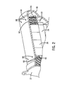
- FIGS. 1 and 2 illustrate an electric machine module 10 according to one embodiment of the invention.
- the module 10 can include a housing 12 comprising a sleeve member 14, a first end cap 16, and a second end cap 18.
- An electric machine 20 can be housed within a machine cavity 22 at least partially defined by the sleeve member 14 and the end caps 16, 18.
- the sleeve member 14 and the end caps 16, 18 can be coupled via conventional fasteners (not shown), or another suitable coupling method, to enclose at least a portion of the electric machine 20 within the machine cavity 22.
- the housing 12 can comprise a substantially cylindrical canister 15 coupled to an end cap 17, as shown in FIG. 2 .
- the housing 12, including the sleeve member 14 and the end caps 16, 18, can comprise materials that can generally include thermally conductive properties, such as, but not limited to aluminum or other metals and materials capable of generally withstanding operating temperatures of the electric machine.
- the housing 12 can be fabricated using different methods including casting, molding, extruding, and other similar manufacturing methods.
- the electric machine 20 can include a rotor assembly 24, a stator assembly 26, and bearings 28, and can be disposed about a shaft 30. As shown in FIG. 1 , the stator assembly 26 can substantially circumscribe at least a portion of the rotor assembly 24. In some embodiments, the rotor assembly 24 can also include a rotor hub 32 or can have a "hub-less" design (not shown).
- the electric machine 20 can be coupled to the housing 12.
- the electric machine 20 can be fitted within the housing 12.
- the electric machine 20 can be fitted within the housing 12 using an interference fit, a shrink fit, other similar friction-based fits that can at least partially couple the machine 20 and the housing 12.
- the stator assembly 26 can be shrunk fit into the module housing 12.
- the fit can at least partially secure the stator assembly 26, and as a result, the electric machine 20, in axial, radial and circumferential directions.
- the fit between the stator assembly 26 and the housing 12 can at least partially serve to transfer torque from the stator assembly 26 to the housing 12.
- the fit can result in a generally greater amount of torque retained by the module 10.
- the stator assembly 26 can comprise a stator core 34 and a stator winding 36 at least partially disposed within a portion of the stator core 34.
- the stator core 34 can comprise a plurality of laminations 38.
- the laminations 38 can comprise a plurality of substantially radially-oriented teeth 40.
- the teeth 40 can substantially align to define a plurality of slots 42 that are configured and arranged to support at least a portion of the stator winding 36. As shown in FIG.
- the laminations 38 can include sixty teeth 40, and, as a result, the stator core 28 can include sixty slots 42. In other embodiments, the laminations 38 can include more or fewer teeth 40, and, accordingly, the stator core 34 can include more or fewer slots 42. Moreover, in some embodiments, the stator core 34 can comprise an inner perimeter 41 and an outer perimeter 43. For example, in some embodiments, the stator core 34 can comprise a substantially cylindrical configuration so that the inner and outer perimeters 41, 43 can comprise inner and outer diameters, respectively.
- stator core 34 can comprise other configurations (e.g., square, rectangular, elliptical, regular or irregular polygonal, etc.), and, as a result, the inner and outer perimeters 41, 43 can comprise other dimensions.
- the stator winding 36 can comprise a plurality of conductors 44.
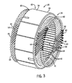
- the conductors 44 can comprise a substantially segmented configuration (e.g., a hairpin configuration), as shown in FIGS. 3 and 5 .
- at least a portion of the conductors 44 can include a turn portion 46 and at least two leg portions 48.
- the turn portion 46 can be disposed between the two leg portions 48 to substantially connect the two leg portions 48.
- the leg portions 48 can be substantially parallel.
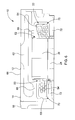
- the turn portion 46 can comprise a substantially "u-shaped" configuration, although, in some embodiments, the turn portion 46 can comprise a v-shape, a wave shape, a curved shape, and other shapes. Additionally, in some embodiments, as shown in FIG. 5 , at least a portion of the conductors 44 can comprise a substantially rectangular cross section. In some embodiments, at least a portion of the conductors 44 can comprise other cross-sectional shapes, such as substantially circular, square, hemispherical, regular or irregular polygonal, etc. In some embodiments, the conductors 44 can comprise other configurations (e.g., substantially non-segmented configuration).
- the conductors 44 can be positioned substantially within the slots 42.
- the stator core 34 can be configured so that the plurality of slots 42 are substantially axially arranged.
- the leg portions 48 can be inserted into the slots 42 so that at least some of the leg portions 48 can axially extend through the stator core 34.
- the leg portions 48 can be inserted into neighboring slots 42.
- the leg portions 48 of a conductor 44 can be disposed in slots that are distanced approximately one magnetic-pole pitch apart (e.g., six slots, eight slots, etc.).
- a plurality of conductors 44 can be disposed in the stator core 34 so that at least some of the turn portions 46 of the conductors 44 axially extend from the stator core 34 at a first axial end 50 of the stator core 34 and at least some of the leg portions 48 axially extend from the stator core 34 at a second axial end 52 of the stator core 34.
- at least a portion of the conductor 44 regions that axially extend from the core 34 at the axial ends 50, 52 can comprise stator end turns 54.
- the conductors 44 can be generally fabricated from a substantially linear conductor 44 that can be configured and arranged to a shape substantially similar to the conductor in FIG. 5 .
- a machine (not shown) can apply a force (e.g., bend, push, pull, other otherwise actuate) to at least a portion of a conductor 44 to substantially form the turn portion 46 and the leg portions 48 from a conductor 44.
- the leg portions 48 can comprise multiple regions.
- the leg portions 48 can comprise in-slot portions 56, angled portions 58, and connection portions 60.
- the leg portions 48 can be disposed in the slots 42 and can axially extend from the first end 50 to the second end 52.
- at least a portion of the leg portions 48 positioned within the slots 42 can comprise the in-slot portions 56.
- stator end turns 54 extending from stator core 34 at the second axial end 52 can comprise the angled portions 58 and the connection portions 60.
- the leg portions 48 extending from the stator core 34 at the second axial end 52 can undergo a twisting process (not shown) that can lead to the creation of the angled portions 58 and the connection portions 60.
- the twisting process can give rise to the angled portions 58 at a more axially inward position and the connection portions 60 at a more axially outward position, as shown in FIGS. 3 and 5 .
- connection portions 60 of at least a portion of the conductors 44 can be immediately adjacent to connection portions 60 of other conductors 44.
- the connection portions 60 can be coupled together to form one or more stator windings 36.
- the connection portions 60 can be coupled via welding, brazing, soldering, melting, adhesives, or other coupling methods.
- the angled portions 58 and the connection portions 60 can extend from the first axial end 50 and can be configured and arranged in a similar manner as some previously mentioned embodiments.
- some components of the electric machine 20 such as, but not limited to, the rotor assembly 24, the stator assembly 26, and the stator end turns 54, can generate heat during operation of the electric machine 20. These components can be cooled to increase the performance and the lifespan of the electric machine 20.
- dissipation of heat energy at the stator end turns 54 can be insufficient to ensure efficient operations of the electric machine 20.
- heat energy can be produced by the stator end turns 54 as a result of current flowing through the end turns 54 during operation of the electric machine 20.
- Convection of the heat energy via air in the machine cavity 22 to the stator core 34 and/or the housing 12 can be substantially insufficient because air comprises relatively poor thermal conductivity properties.
- the stator end turns 54 can exhibit relatively large copper losses, which can result in inefficient operation of the electric machine 20.
- the housing 12 can comprise a coolant jacket 62.
- the housing 12 can include an inner wall 64 and an outer wall 66 and the coolant jacket 62 can be positioned substantially between at least a portion the walls 64, 66.
- the machine cavity 22 can be at least partially defined by the inner wall 64 (e.g., each of the elements of the housing 12 can comprise a portion of the inner wall 64).
- the coolant jacket 62 can substantially circumscribe at least a portion of the electric machine 20.
- the coolant jacket 62 can substantially circumscribe at least a portion of the outer perimeter 43 of the stator assembly 26, including the stator end turns 54.
- one or more coolant jackets 62 can be disposed and/or through other portions of the housing 12, in addition to or in lieu of the coolant jacket 62 disposed within the sleeve member 14.
- at least a portion of a coolant jacket 62 can be disposed through portions of the end caps 16, 17, 18 or the canister 15.
- the coolant jacket 62 can contain a coolant that can comprise a liquid.
- the coolant can comprise a liquid coolant that can at least partially wet one or more internal surfaces of the electric machine 10.
- a liquid coolant can at least partially wet one or more internal surfaces (for example inner wall 64) of the coolant jacket 62.
- a liquid coolant can at least partially wet the internal surfaces of a coolant aperture 68.
- a liquid coolant can at least partially wet one or more internal surfaces of at least one end turn cavity 70.
- the electric machine 10 can be configured and arranged for a liquid coolant to wet the surface of one or more stator end turns.
- a liquid coolant can wet one or more surfaces of the machine cavity.
- the coolant can comprise a transmission fluid, ethylene glycol, an ethylene glycol / water mixture, water, or an oil, including, but not limited to a motor oil, a gear oil, synthetic oil or other hydrocarbon-based fluid.
- the coolant may comprise a fluid such as a gas, a mist, or a similar substance.
- the coolant jacket 62 can be in fluid communication with a coolant source (not shown) which can pressurize the coolant prior to or as it is being dispersed into the coolant jacket 62, so that the pressurized coolant can circulate through the coolant jacket 62.
- At least a portion of the housing 12 can comprise at least one coolant aperture 68. In some embodiments, the housing 12 can comprise a plurality of coolant apertures 68. In some embodiments, at least a portion of the coolant apertures 68 can be disposed through a portion of the housing 12 to fluidly connect the coolant jacket 62 and the machine cavity 22 and portions of the electric machine 20. For example, in some embodiments, at least a portion of the coolant apertures 68 can be disposed through a portion of the inner wall 64 of the housing 12 to fluidly connect the coolant jacket 62 with the machine cavity 22.
- At least a portion of coolant circulating through the coolant jacket 62 can be pressurized so that as coolant circulates through the coolant jacket 62, at least a portion of the coolant can pass through the coolant apertures 68 can enter the machine cavity 22. In some other embodiments, at least a portion of the coolant can pass through the coolant apertures 68 and enter the end turn cavity or the machine cavity under gravity flow.
- the electric machine module 10 can comprise configurations to facilitate cooling of some components of the electric machine. These components can be cooled to enhance the performance of, and increase the lifetime of the electric machine.
- the electric machine module 10 can comprise configurations to facilitate cooling of at least the stator end turns.
- the electric machine module 10 can comprise at least one end turn cavity 70.
- the module 10 can comprise at least two end turn cavities 70.
- at least a portion of the end turns 54 extending from the first and the second axial ends 50, 52 can be at least partially disposed within the end turn cavities 70.
- some or all of the end turns 54 can be disposed within the end turn cavities 70.
- the end turn cavities 70 can be configured and arranged to contain a coolant.
- the end turn cavities 70 can be fluidly connected to the coolant jacket 62 via a coolant aperture 68.
- the coolant can be substantially stagnant within the end turn cavities 70, whereas in other embodiments, the end turn cavities can be configured and arranged to enable coolant to flow through the end turn cavities.
- the end turn cavities 70 can be substantially or completely sealed relative to the machine cavity 22, as described in further detail below. For example, any fluid circulating through the end turn cavities 70 can either wholly remain within the cavities 70 or a portion of the fluid can exit the cavities 70 and enter the machine cavity 22.
- the end turn cavities 70 can comprise multiple configurations.
- a single end turn cavity 70 can circumferentially surround the stator end turns 54 at one or both of the first axial end 50 and the second axial end 52 (e.g., all of the stator end turns 54 can be disposed within the end turn cavities 70).
- the end turn cavities 70 can be disposed around a lesser proportion of the stator end turns 54. For example, 10%, 20%, 50%, 75%, etc. of the stator end turns 54 extending from the stator core 34 can be disposed within the end turn cavities 70.
- the end turn cavities 70 can surround different portions of the stator end turns 54 at the first and second axial ends 50, 52.
- stator end turns 54 on the first axial end 50, approximately 100% of the stator end turns 54 can be disposed within the end turn cavities 70 and on the second axial end 52, 75% of the stator end turns 54 can be disposed within the end turn cavities 70. In other embodiments, any proportion of the stator end turns 54 on either the first or the second axial ends 50, 52 of the stator assembly 26 can be housed within the end turn cavities 70 to meet manufacturer or user needs.
- the electric machine module 10 can comprise a plurality of flanges 72 that are configured and arranged to define the cavities 70.
- the flanges 72 can be coupled to portions of the inner walls 64 and/or a portion of the stator assembly 26.
- the flanges 72 can be coupled to the inner wall 64 of the housing 12 and extend axially inward so that when the stator assembly 26 is positioned within the machine cavity 22, at least a portion of the stator end turns 54 are disposed within the end turn cavities 70 (e.g., between the flanges 72).
- the cavities 70 can comprise at least three flanges 72 and can be coupled to at least one of the stator end turns 54 and the stator core 34.
- the flanges 72 can be coupled together to define the end turn cavity 70.
- the flanges 72 can be formed as one integral piece so that the individual flanges 72 need not be coupled together.
- the flanges 72 can be coupled to the stator core 34 and/or the end turns 54 via brazing, welding, conventional fasteners, friction fitting, interference fitting, adhesives, any other conventional coupling technique, or any combination thereof.
- the flanges 72 can comprise a substantially non-electrically conductive material. An electric current circulates through the conductors 44 during electric machine 20 operations, and, in order to prevent short circuits and grounding events, any materials adjacent to the end turns 54, including the flanges 72 preferably comprise non-electrically conductive properties. Accordingly, the flanges 72 can be coupled to at least one of the stator core 34, the end turns 54, and the housing 12 to define the end turn cavities 70 substantially surrounding at least a portion of the stator end turns 54. In some embodiments, the flanges 72 can comprise a polymer. In other embodiments, the flanges 72 can comprise a non-electrically conductive composite. In some embodiments, the flanges 72 can be can comprise a non-electrically conductive coating.
- At least some of the coolant apertures 68 can fluidly couple the coolant jacket 62 to at least one of the end turn cavities 70.
- at least a portion of the end turn cavities 70 can include at least one inlet (not shown) so that coolant can flow from the coolant apertures 68 into the end turn cavities 70.
- coolant can flow from the coolant apertures 68 to the end turn cavities 70 via a substantially sealed structure (e.g., a hose, tube, or other structure capable of containing a portion of the flowing coolant).
- coolant can flow from the coolant apertures 68, enter the machine cavity 22, and at least a portion of the coolant can passively enter at least some of the end turn cavities 70.
- At least one outlet can be disposed through a portion of the flanges 72 and can be fluidly coupled to a drain system (not shown) so that the at least a portion of the coolant within the end turn cavities 70 can flow to the drain system.
- the end turn cavities 70 can be substantially sealed relative to some portions of the module 10.
- at least some of the end turn cavities 70 can comprise a volume of coolant that is substantially similar to the maximum allowable volume of the cavities 70 (e.g., the cavities 70 are substantially or completely full of coolant).
- each of the end turns 54 disposed within the end turn cavities 70 can be substantially surrounded by coolant circulating through the cavities 70 and can transfer at least a portion of the heat energy produced during operations of the electric machine module 10.
- the electric machine 20 can be at least partially cooled by the circulating coolant, which can lead to improved operations.
- the end turn cavities 70 can function without being substantially sealed.
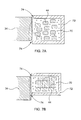
- the end turn cavities 70 can comprise a gap 74 between the flanges 72 and the stator core 34, as shown in FIGS. 7A and 7B .
- the end turn cavities 70 can comprise a near maximum or maximum of volume of coolant even when not completely sealed because the rate of coolant circulation through the end turn cavities 70 can be increased to a great enough level to ensure sufficient levels of coolant within the cavities 70 (e.g., enough coolant present within the cavities 70 to contact multiple regions of the stator end turns 54).
- the gap 74 can be present and can be substantially sealed by a sealing structure (e.g., a plug) (not shown).
- some conventional electric machine modules 10 can comprise a coolant jacket 62 and coolant apertures 68 that direct coolant from the jacket 62 directly onto the stator end turns 54.
- This configuration can result in substantially uneven cooling.
- the coolant flow from the apertures 68 to the stator end turns 54 can be influenced by gravity, geometries of the conductors 44 (e.g., the shape of the conductors 44), air circulation within the machine cavity 22 caused by the spinning rotor assembly 24, and other potentially disruptive factors.
- the coolant flow from the coolant jacket 62 can be unintentionally redirected away from the stator end turns 54, which can create under-cooled regions and even some non-cooled regions of the conductors 44.
- conductor 44 hot spots and uneven temperature distributions can arise, which can lead to inefficient electric machine module 10 operations.
- Some embodiments of the invention can improve at least a portion of the previously mentioned cooling issues. For example, factors creating difficulty in cooling (e.g., gravity, conductor geometry, and air circulation within the machine cavity 22) can be substantially avoided because coolant can be directly routed to the end turn cavities 70 and contact a greater proportion of the end turns 54 relative to some conventional configurations. Moreover, more surface area of the conductors 44 can be exposed to coolant, which can lead to improved heat energy transfer because the stator end turns 54 disposed within the end turn cavities 70 can be substantially or completely covered in circulating coolant. As a result, cooling of the electric machine module 10 can be improved, and accordingly, so can module 10 operations.
- factors creating difficulty in cooling e.g., gravity, conductor geometry, and air circulation within the machine cavity 22
- coolant can be directly routed to the end turn cavities 70 and contact a greater proportion of the end turns 54 relative to some conventional configurations.
- more surface area of the conductors 44 can be exposed to coolant, which can lead to improved heat energy transfer because the stator
Landscapes
- Engineering & Computer Science (AREA)
- Power Engineering (AREA)
- Manufacturing & Machinery (AREA)
- Motor Or Generator Frames (AREA)
- Motor Or Generator Cooling System (AREA)
Applications Claiming Priority (2)
| Application Number | Priority Date | Filing Date | Title |
|---|---|---|---|
| US201161568429P | 2011-12-08 | 2011-12-08 | |
| US13/706,629 US20130147289A1 (en) | 2011-12-08 | 2012-12-06 | Electric machine module cooling system and method |
Publications (2)
| Publication Number | Publication Date |
|---|---|
| EP2605381A2 true EP2605381A2 (de) | 2013-06-19 |
| EP2605381A3 EP2605381A3 (de) | 2016-01-06 |
Family
ID=47632697
Family Applications (1)
| Application Number | Title | Priority Date | Filing Date |
|---|---|---|---|
| EP12196178.3A Withdrawn EP2605381A3 (de) | 2011-12-08 | 2012-12-07 | Elektromaschinenmodul-Kühlsystem und Verfahren |
Country Status (4)
| Country | Link |
|---|---|
| US (1) | US20130147289A1 (de) |
| EP (1) | EP2605381A3 (de) |
| KR (1) | KR20130066517A (de) |
| CN (1) | CN103280925A (de) |
Families Citing this family (11)
| Publication number | Priority date | Publication date | Assignee | Title |
|---|---|---|---|---|
| DE102015100090A1 (de) * | 2014-01-17 | 2015-07-23 | Ecomotors, Inc. | Kühlung von Statorspulen einer elektrischen Maschine |
| JP6181592B2 (ja) * | 2014-04-11 | 2017-08-16 | トヨタ自動車株式会社 | 回転電機冷却装置 |
| JP6591198B2 (ja) * | 2015-05-22 | 2019-10-16 | 日立オートモティブシステムズ株式会社 | 回転電機の固定子 |
| WO2018218314A1 (en) * | 2017-06-02 | 2018-12-06 | magniX Technologies Pty Ltd | Cooling arrangements in devices or components with windings |
| DE102017213513A1 (de) * | 2017-08-03 | 2019-02-07 | Zf Friedrichshafen Ag | Ölversorgungsanordnung eines Fahrzeuges mit einer elektrischen Maschine |
| US10910916B2 (en) * | 2017-11-30 | 2021-02-02 | General Electric Company | Fluid cooled and fluid insulated electric machine |
| US11469647B2 (en) * | 2019-06-07 | 2022-10-11 | Borgwarner Inc. | Oil cooling system for a stator of an electric machine |
| FR3105631B1 (fr) * | 2019-12-18 | 2023-05-26 | Novares France | Stator pour moteur électrique |
| DE102020103437A1 (de) * | 2020-02-11 | 2021-08-12 | Schaeffler Technologies AG & Co. KG | Elektrische Antriebseinrichtung und Antriebsanordnung |
| US12278540B2 (en) * | 2022-09-28 | 2025-04-15 | Honda Motor Co., Ltd. | Cooling structure of vertical motor |
| EP4369571A1 (de) | 2022-11-10 | 2024-05-15 | Airbus Operations, S.L.U. | Verbesserte interne kühlsysteme für e-maschinen |
Family Cites Families (25)
| Publication number | Priority date | Publication date | Assignee | Title |
|---|---|---|---|---|
| GB146624A (en) * | 1920-04-10 | 1920-07-12 | Siemens Brothers Dynamo Works | Improvements relating to dynamo electric machines |
| US2295404A (en) * | 1940-07-19 | 1942-09-08 | Westinghouse Electric & Mfg Co | Dynamoelectric machine |
| US2282283A (en) * | 1940-08-03 | 1942-05-05 | Allis Chalmers Mfg Co | Dynamoelectric machine |
| US2413525A (en) * | 1944-02-10 | 1946-12-31 | Allis Louis Co | Totally enclosed dynamoelectric machine |
| US2618756A (en) * | 1949-06-06 | 1952-11-18 | Carl J Fechheimer | Liquid cooled electrical machine |
| US2571872A (en) * | 1949-11-09 | 1951-10-16 | Reliance Electric & Eng Co | Electric motor frame having coolant system incorporated therein |
| US2611798A (en) * | 1950-12-22 | 1952-09-23 | Reliance Electric & Eng Co | Electric motor frame having coolant system incorporated therein |
| US2862120A (en) * | 1957-07-02 | 1958-11-25 | Onsrud Machine Works Inc | Fluid-cooled motor housing |
| US3009072A (en) * | 1958-01-28 | 1961-11-14 | Scott L & Electromotors Ltd | Fluid cooled motors |
| US2951954A (en) * | 1959-02-12 | 1960-09-06 | Gen Electric | Fluid-coupled rotor for dynamoelectric machine |
| US3240967A (en) * | 1959-07-31 | 1966-03-15 | Krastchew Christoslaw | Cooling arrangement for electric machines |
| US3238400A (en) * | 1963-02-04 | 1966-03-01 | Task Corp | Gas input assisted evacuation of rotor-stator gaps |
| US3439201A (en) * | 1965-10-06 | 1969-04-15 | Gen Motors Corp | Cooling arrangement for dynamoelectric machines |
| US3445695A (en) * | 1966-05-25 | 1969-05-20 | Borg Warner | Cooling system for hermetic dynamoelectric devices |
| US4854373A (en) * | 1988-03-30 | 1989-08-08 | Williams Gordon G | Heat exchanger for a pump motor |
| AU7315394A (en) * | 1993-07-15 | 1995-02-13 | Onan Corporation | Auxiliary power system for hybrid electric vehicle |
| JP3661529B2 (ja) * | 1999-11-17 | 2005-06-15 | 日産自動車株式会社 | モータの冷却装置 |
| JP3967624B2 (ja) * | 2002-04-26 | 2007-08-29 | 株式会社日本自動車部品総合研究所 | 電動機 |
| JP3685169B2 (ja) * | 2002-09-27 | 2005-08-17 | 株式会社日立製作所 | 回転機及びその製造法 |
| JP2004215353A (ja) * | 2002-12-27 | 2004-07-29 | Toyota Motor Corp | 回転電機 |
| US7009317B2 (en) * | 2004-01-14 | 2006-03-07 | Caterpillar Inc. | Cooling system for an electric motor |
| JP5088577B2 (ja) * | 2008-08-22 | 2012-12-05 | アイシン・エィ・ダブリュ株式会社 | 回転電機 |
| JP5368866B2 (ja) * | 2009-04-21 | 2013-12-18 | 株式会社日本自動車部品総合研究所 | 回転電機 |
| MX2012011570A (es) * | 2010-05-04 | 2013-01-29 | Remy Technologies Llc | Sistema y metodo de enfriamiento de maquina electrica. |
| EP2567450A4 (de) * | 2010-05-04 | 2018-01-17 | Remy Technologies, LLC | Kühlsystem und -verfahren für eine elektromaschine |
-
2012
- 2012-12-06 US US13/706,629 patent/US20130147289A1/en not_active Abandoned
- 2012-12-07 EP EP12196178.3A patent/EP2605381A3/de not_active Withdrawn
- 2012-12-10 CN CN2012105990032A patent/CN103280925A/zh active Pending
- 2012-12-10 KR KR1020120142488A patent/KR20130066517A/ko not_active Withdrawn
Non-Patent Citations (1)
| Title |
|---|
| None * |
Also Published As
| Publication number | Publication date |
|---|---|
| CN103280925A (zh) | 2013-09-04 |
| KR20130066517A (ko) | 2013-06-20 |
| US20130147289A1 (en) | 2013-06-13 |
| EP2605381A3 (de) | 2016-01-06 |
Similar Documents
| Publication | Publication Date | Title |
|---|---|---|
| EP2605381A2 (de) | Elektromaschinenmodul-Kühlsystem und Verfahren | |
| US8803380B2 (en) | Electric machine module cooling system and method | |
| US9099900B2 (en) | Electric machine module cooling system and method | |
| US8629585B2 (en) | Internal cooling of stator assembly in an electric machine | |
| US8975792B2 (en) | Electric machine module cooling system and method | |
| US8624452B2 (en) | Electric machine module cooling system and method | |
| CN103155376B (zh) | 用于电机定子的冷却剂通道 | |
| US20110273040A1 (en) | Electric Machine Cooling System and Method | |
| EP4641889A2 (de) | Kühlsystem und -verfahren für eine elektromaschine | |
| EP2571146A2 (de) | Elektromaschinenmodul-Kühlsystem und Herstellungsverfahren | |
| WO2012047478A2 (en) | Coolant channels for electric machine stator | |
| KR20130109970A (ko) | 전기 기계를 위한 슬리브 부재 | |
| US20130002067A1 (en) | Electric Machine Module Cooling System and Method | |
| KR20140008518A (ko) | 전기 기계 냉각 시스템 및 방법 | |
| KR20130006335A (ko) | 전기 기기의 냉각 시스템 및 방법 | |
| US20230072181A1 (en) | Stator for an electric motor | |
| JP7781569B2 (ja) | モータ | |
| US20130076167A1 (en) | Cooling system and method for electronic machines | |
| KR20130032828A (ko) | 전기 기계 모듈 냉각 시스템 및 방법 | |
| US10069375B2 (en) | Electric machine module cooling system and method | |
| KR20140049554A (ko) | 전기 기계 모듈 | |
| US20120262013A1 (en) | Electric Machine Module Cooling System and Method | |
| EP2546960B1 (de) | Elektrische Maschine Modul Kühlungsystem und Verfahren | |
| JP7734539B2 (ja) | モータ |
Legal Events
| Date | Code | Title | Description |
|---|---|---|---|
| PUAI | Public reference made under article 153(3) epc to a published international application that has entered the european phase |
Free format text: ORIGINAL CODE: 0009012 |
|
| AK | Designated contracting states |
Kind code of ref document: A2 Designated state(s): AL AT BE BG CH CY CZ DE DK EE ES FI FR GB GR HR HU IE IS IT LI LT LU LV MC MK MT NL NO PL PT RO RS SE SI SK SM TR |
|
| AX | Request for extension of the european patent |
Extension state: BA ME |
|
| PUAL | Search report despatched |
Free format text: ORIGINAL CODE: 0009013 |
|
| AK | Designated contracting states |
Kind code of ref document: A3 Designated state(s): AL AT BE BG CH CY CZ DE DK EE ES FI FR GB GR HR HU IE IS IT LI LT LU LV MC MK MT NL NO PL PT RO RS SE SI SK SM TR |
|
| AX | Request for extension of the european patent |
Extension state: BA ME |
|
| RIC1 | Information provided on ipc code assigned before grant |
Ipc: H02K 5/20 20060101ALI20151201BHEP Ipc: H02K 3/24 20060101ALN20151201BHEP Ipc: H02K 9/19 20060101AFI20151201BHEP |
|
| 17P | Request for examination filed |
Effective date: 20160706 |
|
| RBV | Designated contracting states (corrected) |
Designated state(s): AL AT BE BG CH CY CZ DE DK EE ES FI FR GB GR HR HU IE IS IT LI LT LU LV MC MK MT NL NO PL PT RO RS SE SI SK SM TR |
|
| 17Q | First examination report despatched |
Effective date: 20170404 |
|
| STAA | Information on the status of an ep patent application or granted ep patent |
Free format text: STATUS: THE APPLICATION IS DEEMED TO BE WITHDRAWN |
|
| 18D | Application deemed to be withdrawn |
Effective date: 20171017 |