EP2605924B1 - Amortisseur électrique pour un véhicule à moteur - Google Patents
Amortisseur électrique pour un véhicule à moteur Download PDFInfo
- Publication number
- EP2605924B1 EP2605924B1 EP11740568.8A EP11740568A EP2605924B1 EP 2605924 B1 EP2605924 B1 EP 2605924B1 EP 11740568 A EP11740568 A EP 11740568A EP 2605924 B1 EP2605924 B1 EP 2605924B1
- Authority
- EP
- European Patent Office
- Prior art keywords
- gear
- stage
- damping
- electric damper
- damper according
- Prior art date
- Legal status (The legal status is an assumption and is not a legal conclusion. Google has not performed a legal analysis and makes no representation as to the accuracy of the status listed.)
- Not-in-force
Links
Images

Classifications
-
- F—MECHANICAL ENGINEERING; LIGHTING; HEATING; WEAPONS; BLASTING
- F16—ENGINEERING ELEMENTS AND UNITS; GENERAL MEASURES FOR PRODUCING AND MAINTAINING EFFECTIVE FUNCTIONING OF MACHINES OR INSTALLATIONS; THERMAL INSULATION IN GENERAL
- F16F—SPRINGS; SHOCK-ABSORBERS; MEANS FOR DAMPING VIBRATION
- F16F15/00—Suppression of vibrations in systems; Means or arrangements for avoiding or reducing out-of-balance forces, e.g. due to motion
- F16F15/02—Suppression of vibrations of non-rotating, e.g. reciprocating systems; Suppression of vibrations of rotating systems by use of members not moving with the rotating systems
- F16F15/03—Suppression of vibrations of non-rotating, e.g. reciprocating systems; Suppression of vibrations of rotating systems by use of members not moving with the rotating systems using magnetic or electromagnetic means
- F16F15/035—Suppression of vibrations of non-rotating, e.g. reciprocating systems; Suppression of vibrations of rotating systems by use of members not moving with the rotating systems using magnetic or electromagnetic means by use of eddy or induced-current damping
-
- B—PERFORMING OPERATIONS; TRANSPORTING
- B60—VEHICLES IN GENERAL
- B60G—VEHICLE SUSPENSION ARRANGEMENTS
- B60G13/00—Resilient suspensions characterised by arrangement, location or type of vibration dampers
- B60G13/14—Resilient suspensions characterised by arrangement, location or type of vibration dampers having dampers accumulating utilisable energy, e.g. compressing air
-
- F—MECHANICAL ENGINEERING; LIGHTING; HEATING; WEAPONS; BLASTING
- F16—ENGINEERING ELEMENTS AND UNITS; GENERAL MEASURES FOR PRODUCING AND MAINTAINING EFFECTIVE FUNCTIONING OF MACHINES OR INSTALLATIONS; THERMAL INSULATION IN GENERAL
- F16F—SPRINGS; SHOCK-ABSORBERS; MEANS FOR DAMPING VIBRATION
- F16F9/00—Springs, vibration-dampers, shock-absorbers, or similarly-constructed movement-dampers using a fluid or the equivalent as damping medium
- F16F9/10—Springs, vibration-dampers, shock-absorbers, or similarly-constructed movement-dampers using a fluid or the equivalent as damping medium using liquid only; using a fluid of which the nature is immaterial
- F16F9/12—Devices with one or more rotary vanes turning in the fluid any throttling effect being immaterial, i.e. damping by viscous shear effect only
-
- B—PERFORMING OPERATIONS; TRANSPORTING
- B60—VEHICLES IN GENERAL
- B60G—VEHICLE SUSPENSION ARRANGEMENTS
- B60G2202/00—Indexing codes relating to the type of spring, damper or actuator
- B60G2202/20—Type of damper
- B60G2202/22—Rotary Damper
-
- B—PERFORMING OPERATIONS; TRANSPORTING
- B60—VEHICLES IN GENERAL
- B60G—VEHICLE SUSPENSION ARRANGEMENTS
- B60G2204/00—Indexing codes related to suspensions per se or to auxiliary parts
- B60G2204/10—Mounting of suspension elements
- B60G2204/12—Mounting of springs or dampers
- B60G2204/128—Damper mount on vehicle body or chassis
-
- B—PERFORMING OPERATIONS; TRANSPORTING
- B60—VEHICLES IN GENERAL
- B60G—VEHICLE SUSPENSION ARRANGEMENTS
- B60G2204/00—Indexing codes related to suspensions per se or to auxiliary parts
- B60G2204/40—Auxiliary suspension parts; Adjustment of suspensions
- B60G2204/419—Gears
- B60G2204/4191—Planetary or epicyclic gears
-
- B—PERFORMING OPERATIONS; TRANSPORTING
- B60—VEHICLES IN GENERAL
- B60G—VEHICLE SUSPENSION ARRANGEMENTS
- B60G2204/00—Indexing codes related to suspensions per se or to auxiliary parts
- B60G2204/40—Auxiliary suspension parts; Adjustment of suspensions
- B60G2204/421—Pivoted lever mechanisms for mounting suspension elements, e.g. Watt linkage
-
- B—PERFORMING OPERATIONS; TRANSPORTING
- B60—VEHICLES IN GENERAL
- B60G—VEHICLE SUSPENSION ARRANGEMENTS
- B60G2300/00—Indexing codes relating to the type of vehicle
- B60G2300/60—Vehicles using regenerative power
Definitions
- the invention relates to an electric damper for a motor vehicle according to the preamble of claim 1.
- Such an electric damper can be used in place of a hydraulic damper in a vibratory mechanical system of a motor vehicle. Like the hydraulic damper, the electric damper also deprives the oscillatory system of energy. However, this is not converted into thermal energy. Rather, with the vibration energy, a generator associated with the electric damper is driven, which converts the vibration energy into electrical energy, which can be fed into the electrical system of the motor vehicle.
- an electric damper for a motor vehicle which is used to damp mechanical oscillations arising between two components.
- the mechanical vibrations are converted into drive torques with which an electric generator for generating an induction voltage can be driven.
- the object of the invention is to provide an electric damper for a vehicle in which a thermal load of the electric damper is reduced during the damping process.
- the generator in the torque flow direction is preceded by a particular hydraulic damping stage.
- the damping stage according to the invention in particular high-frequency vibration components can be damped before they are introduced into the electric damper.
- the hard-to-recuperate by the electric generator energy from high-frequency, small excitations is therefore already in the hydraulic damping stage attenuated. This leads to a good response of the electric damper and also reduces the thermal load of the generator of the electric damper.
- the damping stage operates hydraulically, this can be carried out on the one hand as a hydraulic damping bearing having Häkammem, which are filled with a damping fluid and fluidly connected to each other via flow channels.
- the damper fluid When subjected to mechanical vibrations, the damper fluid is moved back and forth between the working chambers, whereby in particular high-frequency vibrations are damped with comparatively small amplitudes.
- the hydraulic damping stage is a rotary piston arrangement in which a rotary piston is rotatably mounted in a damping housing. Between the rotary piston and the radially outer side damping housing filled with the damper fluid working chambers are formed. In installation position, the rotary piston may optionally be acted upon with the interposition of a suitable transmission with the mechanical vibrations. High-frequency vibrations with low amplitudes can be largely damped in the rotary piston assembly.
- the rotary piston assembly is particularly advantageous in view of the required small length and in view of a greatly reduced space available.
- a suitable transmission of motion of the first, acted upon by the mechanical vibrations component of the hydraulic damping stage is preceded by a first gear stage.
- the transmission ratio of the first gear is calculated so that In the damping stage, an effective damping of the high-frequency vibration components can be performed.
- the remaining in the direction of flow direction after the damping stage, not yet damped vibration component can be passed directly to the generator in a variant.
- a second gear stage is interposed between the damping stage and the generator in the torque flow direction.
- the transmission ratio of the second gear stage may preferably be dimensioned such that a rotor speed suitable for inducing voltage can be achieved in the generator.
- the two gear stages are designed as a planetary gear whose overall length is greatly reduced compared to other types of transmissions. In combination with the realized as a rotary piston arrangement damping stage results in a particularly compact unit.
- the stator of the generator is also integrated as a transmission element in the first gear stage or in the second gear stage.
- Such a configuration results in a very small unit.
- the functional principle of the electric damper resulting from the above configuration is not known from the above prior art, since according to the invention the stator is not a stationary component, but rather is actively rotated during the damping process itself. The rotation of the stator is transmitted via the gear and damping stages to the rotor of the generator. By appropriate gear ratios, the rotor can be rotated with a much larger compared to the stator speed. As a result, the generator can generate the induction voltage in a manner known per se.
- the first component may be a vibration-bearing wheel guiding element of a wheel suspension for a motor vehicle
- the second component may be the stationary vehicle body.
- the wheel guide element may also be pivotally connected via a pivot axis with the vehicle body.
- the hinge axis is arranged coaxially to the axis of rotation of the rotor, the damping stage and / or the two gear stages.
- the mechanical torsional vibrations of the first component can be introduced directly into the stator of the generator.
- the wheel guide element forming the first component can for this purpose be non-rotatably seated, for example in an interference fit, on the stator of the generator, that is to say be non-rotatably inserted into the fastening eye of the wheel guide element.
- the stator of the generator together with the radially outer ring gear of the planetary gear of the first gear stage forms an integral unit.
- the ring gear therefore acts as an input element of the first gear stage.
- the output member of the first gear stage may preferably be the radially inner sun gear that is directly in communication with the hydraulic damper stage.
- the planet carrier of the first planetary gear may be rotatably supported on the second, stationary component.
- the above-mentioned output element of the first planetary gear may also be non-rotatably connected to the planetary carrier of the planetary gear of the second gear stage acting as input element.
- the planet carrier The second planetary gear may additionally be designed as a rotary piston in a dual function, which is rotatably mounted in the damper hydraulic housing in the damper housing, as already mentioned above.
- the damper housing of the rotary piston arrangement may preferably be mounted on the stationary second component, that is to say the vehicle body.
- the ring gear of the planetary gear of the second gear stage can be rotatably connected to the second, fixed component and particularly preferably be integrated directly into the damping housing and act as a torque arm.
- the sun gear of the second planetary gear may be connected as an output element drivingly connected to the rotor of the generator to direct the drive torque to the generator.
- Fig. 1 the suspension of a vehicle wheel 1 of a motor vehicle is shown.
- the vehicle wheel 1 is rotatably mounted on a wheel carrier 3.
- the wheel carrier 3 is articulated via wishbone 5 on the vehicle body 7.
- a trailing arm 9 acts on the wheel carrier 3, which is connected via a coupling 11 with the vehicle body 7.
- the coupling 11 is in the Fig. 1 at a pivot point S about a pivot axis D pivotally connected to the vehicle body 7.
- the articulation point S between the coupling 11 and the vehicle body 7 is enlarged and shown in partial exploded view.
- the coupling 11 has a fastening eye 13 which is attached via an electric damper 15 to a retaining console 16 indicated only by dashed lines, as in the Fig. 2 is shown.
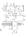
- the electric damper 15 has according to the Fig. 3 a réellepolgenerator 17, which includes a radially outer stator 18 and a rotor 19 cooperating therewith.
- the approximately hollow cylindrical stator 18 carries on its inside not shown induction coils, which cooperate with also not shown electromagnet of the rotor 19.
- According to the Fig. 2 and 3 carries the stator 18 at its outer peripheral side in interference fit the coupling 11.
- the windings can also sit on the rotor and the field magnets sit on the stator.
- the stator 18 via two gear stages I, II and an interposed hydraulic damper stage III is drivingly connected to the rotor 19 of the generator 17 in connection.
- the stator 18 according to the Fig. 3 extended to the right edge of the picture by a ring gear 20 to the right.
- the larger in diameter compared to the stator 18 ring gear 20 connects in the axial direction via a step to the stator 18 and forms a torque input element designed as a planetary gear transmission stage I.
- the ring gear 20 meshes with its internal toothing 21 with planet wheels 22. These are in meshing engagement with a sun gear 23, which is arranged coaxially with the axis of rotation A of the rotor 19.
- the planet gears 22 of the first gear stage I are according to the Fig. 3 rotatably mounted on a planet carrier 25. This is in turn rotatably formed on a fixed damping housing 27 which is mounted on the already mentioned retaining brackets 16 on the vehicle body 7.
- the sun gear 23 of the first gear stage I is rotatably supported by a hollow shaft 28, on whose, in the Fig. 3 right side of a planet carrier 29 of the second gear stage II is formed.
- the second gear stage II, as well as the first gear stage I designed as a planetary gear, wherein the planetary gears 30 radially outwardly mesh with an internal toothing 33 of the damping housing 27 mounted on the vehicle body 7.
- the sun gear 35 of the second gear stage II which meshes with the planetary gears 30 in meshing engagement, forms the torque output element.
- the sun gear 35 is also drivingly connected to the rotor 19 of the generator 17 via a drive shaft 36 coaxial with the hollow shaft 28.
- the planetary gear carrier 29 of the second gear stage II serves as an input element, via which drive torques are introduced into the second gear stage II.
- the planet carrier 29 is not only the input element of the second gear stage II, but also part of the damping stage III.
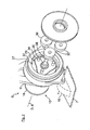
- This is in the present embodiment as a hydraulic Rotary piston arrangement executed, as in the Fig. 2 is illustrated.
- the planet carrier 29 is rotatably supported as a disk-shaped rotary piston in the damper housing 27.
- a total of three working chambers 37 are defined. These are connected to each other via flow channels, not shown.
- the working chambers 37 are also filled with a damper fluid.
- Fig. 2 are also located on the planet carrier 29 journals 39 can be seen on which the planet gears 30 of the second gear stage II are rotatably mounted. These are, as already mentioned, with one in the Fig. 2 Internal toothing 33, not shown, of the damping housing 27 in meshing engagement.
- the drive shaft 36 is in accordance with the Fig. 2 and 3 coaxial to the pivot axis D of the articulation point. 5
- the coupling 11 is acted upon by operational, mechanical vibrations resulting in torsional vibrations B of the coupling 11 with respect to the pivot axis D.
- torsional vibrations B of the stator 18 is driven with drive torque.
- These drive torques are introduced in a torque flow direction M via the ring gear 20 into the first gear stage I.
- Their transmission ratio is dimensioned such that in the, in the torque flow direction M downstream attenuation stage III results in an effective damping of particular high-frequency vibration components.
- the drive torques are introduced by the planet carrier 29 in the second gear II.
- the Hydraulic damping takes place, as mentioned above, directly on the planet gear 29 of the second gear stage.
- the transmission ratio of the damping stage III downstream second gear stage II is dimensioned so that even with small or long-wave mechanical vibrations results in a suitable for an effective voltage induction rotor speed.
Landscapes
- Engineering & Computer Science (AREA)
- General Engineering & Computer Science (AREA)
- Mechanical Engineering (AREA)
- Physics & Mathematics (AREA)
- Electromagnetism (AREA)
- Acoustics & Sound (AREA)
- Aviation & Aerospace Engineering (AREA)
- Retarders (AREA)
- Arrangement Or Mounting Of Propulsion Units For Vehicles (AREA)
Claims (13)
- Amortisseur électrique pour un véhicule afin d'amortir les vibrations torsionnelles mécaniques (B) se produisant entre deux éléments structurels (7, 11), par lesquels des couples d'entraînement sont transmissibles dans une direction d'écoulement de couples (M) sur un générateur électrique (17) pour la production d'une tension d'induction, caractérisé en ce que, en amont du générateur (17), dans la direction d'écoulement de couples (M), est commuté un étage d'amortissement hydraulique (III), qui amortit les fractions de vibrations torsionnelles très fréquentes, et l'étage d'amortissement hydraulique (III) est un aménagement à piston rotatif, dans lequel un piston rotatif (29) est monté à rotation dans un boîtier d'amortissement (20), tandis que des chambres de travail remplies d'un fluide d'amortissement sont formées entre le piston rotatif (29) et le boîtier d'amortissement (20), dans lequel le fluide d'amortissement s'écoule dans un sens ou l'autre entre les chambres de travail (37) à la suite des vibrations torsionnelles mécaniques (B), et en amont de l'étage d'amortissement hydraulique (III) est commuté un étage de transmission (I) dont le rapport de vitesse est tel qu'un amortissement efficace des fractions de vibrations torsionnelles très fréquentes puisse être assuré dans l'étage d'amortissement (III).
- Amortisseur électrique selon la revendication 1, caractérisé en ce qu'en aval de l'étage d'amortissement (III) est commuté un second étage de transmission (II) dont le rapport de vitesse est tel qu'une vitesse de rotation du rotor convenant à l'induction d'une tension puisse être obtenue dans le générateur (17).
- Amortisseur électrique selon la revendication 1 ou la revendication 2, caractérisé en ce que le premier et/ou le second étage de transmission (I, II) se présente (nt) sous la forme d'un engrenage planétaire.
- Amortisseur électrique selon l'une quelconque des revendications 1, 2 ou 3, caractérisé en ce que le stator (18) du générateur (17) est intégré sous la forme d'un élément de transmission au premier étage de transmission (I) ou au second étage de transmission (II).
- Amortisseur électrique selon la revendication 4, caractérisé en ce que les vibrations torsionnelles mécaniques (B) peuvent être induites par le premier élément structurel (11) dans le stator (18) du générateur (17), dans lequel en particulier le stator (18) du générateur (17) est relié au premier élément structurel (11) solidaire en rotation et, en particulier, le stator (18) est enfoncé dans un oeillet de fixation (13) du premier élément structurel (11) de manière solidaire en rotation.
- Amortisseur électrique selon l'une quelconque des revendications 4 ou 5, caractérisé en ce que la couronne radialement externe (20) de l'engrenage planétaire du premier étage de transmission (I) et le stator (18) du générateur (17) forment une unité structurelle d'un seul tenant et/ou la couronne (20) est l'élément d'entrée de l'engrenage planétaire, par lequel les couples d'entraînement sont induits dans le premier étage de transmission (I).
- Amortisseur électrique selon la revendication 6, caractérisé en ce que la roue solaire radialement interne (23) de l'engrenage planétaire du premier étage de transmission (I) agit comme élément de sortie qui est relié à l'étage d'amortissement (III).
- Amortisseur électrique selon la revendication 7, caractérisé en ce que le porte-satellites (25) de l'engrenage planétaire du premier étage de transmission (I) s'appuie sur le second élément structurel (7) de manière solidaire en rotation.
- Amortisseur électrique selon la revendication 7 ou la revendication 8, caractérisé en ce que la roue solaire (23) du premier étage de transmission (II) est reliée solidaire en rotation au porte-satellites (29) de l'engrenage planétaire du second étage de transmission (II) agissant comme élément d'entrée.
- Amortisseur électrique selon l'une quelconque des revendications 3 à 9, caractérisé en ce que le porte-satellites (29) du second étage de transmission (II) se présente sous la forme d'un piston rotatif de l'étage d'amortissement hydraulique (III).
- Amortisseur électrique selon l'une quelconque des revendications 3 à 10, caractérisé en ce que la couronne (27) de l'engrenage planétaire du second étage de transmission (II) s'appuie solidaire en rotation sur le second élément structurel (7).
- Amortisseur électrique selon l'une quelconque des revendications 3 à 11, caractérisé en ce que la roue solaire (35) de l'engrenage planétaire du second étage de transmission (II) agit comme élément de sortie qui est relié via un arbre d'entraînement (36) au rotor (19) du générateur (17) ... les couples d'entraînement (M).
- Amortisseur électrique selon l'une quelconque des revendications précédentes, caractérisé en ce que le premier élément structurel (11) sujet à des vibrations est un élément de guidage de roues et le second élément structurel fixe (7) est la structure du véhicule sur laquelle l'élément de guidage de roues s'appuie en articulation autour d'un axe de rotation (D), dans lequel en particulier l'axe de rotation (D) est agencé coaxialement à l'axe de rotation (A) du rotor (19), de l'étage d'amortissement (III) et/ou des deux étages de transmission (I, II).
Applications Claiming Priority (2)
| Application Number | Priority Date | Filing Date | Title |
|---|---|---|---|
| DE102010035087A DE102010035087A1 (de) | 2010-08-21 | 2010-08-21 | Elektrischer Dämpfer für ein Kraftfahrzeug |
| PCT/EP2011/003779 WO2012031648A1 (fr) | 2010-08-21 | 2011-07-28 | Amortisseur électrique pour un véhicule à moteur |
Publications (2)
| Publication Number | Publication Date |
|---|---|
| EP2605924A1 EP2605924A1 (fr) | 2013-06-26 |
| EP2605924B1 true EP2605924B1 (fr) | 2014-11-12 |
Family
ID=44582833
Family Applications (1)
| Application Number | Title | Priority Date | Filing Date |
|---|---|---|---|
| EP11740568.8A Not-in-force EP2605924B1 (fr) | 2010-08-21 | 2011-07-28 | Amortisseur électrique pour un véhicule à moteur |
Country Status (4)
| Country | Link |
|---|---|
| EP (1) | EP2605924B1 (fr) |
| CN (1) | CN103097153B (fr) |
| DE (1) | DE102010035087A1 (fr) |
| WO (1) | WO2012031648A1 (fr) |
Families Citing this family (13)
| Publication number | Priority date | Publication date | Assignee | Title |
|---|---|---|---|---|
| KR101416362B1 (ko) | 2012-11-15 | 2014-08-07 | 현대자동차 주식회사 | 차량용 서스펜션의 에너지 회생장치 |
| DE102013203431A1 (de) * | 2013-02-28 | 2014-08-28 | Zf Friedrichshafen Ag | Rotationsdämpfer für ein Fahrzeug |
| DE102013203331A1 (de) * | 2013-02-28 | 2014-08-28 | Zf Friedrichshafen Ag | Rotationsdämpfer für ein Fahrzeug |
| DE102013004012B3 (de) * | 2013-03-08 | 2014-03-06 | Audi Ag | Elektromechanischer Dämpfer |
| CN103851151B (zh) * | 2014-03-15 | 2016-02-17 | 吉林大学 | 矿用车电磁馈能减振器 |
| DE102014206230B4 (de) | 2014-04-02 | 2019-06-27 | Zf Friedrichshafen Ag | Schwingungsdämpfer |
| DE102014216877A1 (de) * | 2014-08-25 | 2016-02-25 | Bayerische Motoren Werke Aktiengesellschaft | Fahrwerk eines Kraftfahrzeugs mit Rotationsdämpfer |
| DE102016221306A1 (de) | 2016-10-28 | 2018-05-03 | Schaeffler Technologies AG & Co. KG | Verstellbare Radaufhängung |
| DE102016221307A1 (de) | 2016-10-28 | 2018-05-03 | Schaeffler Technologies AG & Co. KG | Aktuator |
| CN108302162B (zh) * | 2018-01-26 | 2020-10-27 | 常州工学院 | 基于高阻尼柔性支承架的行星轮系及该支承架的设计方法 |
| US10487928B2 (en) * | 2018-04-03 | 2019-11-26 | GM Global Technology Operations LLC | Planetary torsional vibration absorber system for a vehicle |
| IT202000012553A1 (it) | 2020-05-27 | 2021-11-27 | Marelli Suspension Systems Italy S P A | Veicolo dotato di una sospensione e di un dispositivo rotativo elettromeccanico per il controllo di tale sospensione, e metodo di regolazione del moto di una sospensione di veicolo |
| CN117515103B (zh) * | 2024-01-08 | 2024-04-02 | 石家庄铁道大学 | 电涡流阻尼器 |
Family Cites Families (12)
| Publication number | Priority date | Publication date | Assignee | Title |
|---|---|---|---|---|
| JPS56140545A (en) * | 1980-04-01 | 1981-11-02 | Imazaike Seikou Kk | Damper |
| JPH03239619A (ja) * | 1990-02-16 | 1991-10-25 | Kayaba Ind Co Ltd | 油圧サスペンション装置 |
| US6352143B1 (en) * | 2000-03-09 | 2002-03-05 | Bridgestone/Firestone, Inc. | Vibration damping system using a hydraulic damper with a field responsive fluid control |
| DE10043711B4 (de) * | 2000-09-04 | 2006-01-26 | Sachsenring Zwickau Ag | Aktuator zur aktiven Fahrwerksregelung |
| DE10115858A1 (de) | 2001-03-30 | 2002-10-10 | Bosch Gmbh Robert | Elektrischer Dämpfer |
| DE10306228B4 (de) * | 2003-02-13 | 2010-10-07 | Asturia Automotive Systems Ag | Aktuator zur aktiven Fahrwerksregelung |
| JP2007046695A (ja) * | 2005-08-10 | 2007-02-22 | Mitsubishi Heavy Ind Ltd | 回転機構装置、振動減衰装置 |
| JP4643416B2 (ja) * | 2005-10-26 | 2011-03-02 | トヨタ自動車株式会社 | 車両制振装置 |
| DE102006055733A1 (de) * | 2006-11-25 | 2008-05-29 | Zf Friedrichshafen Ag | Stabilisatoranordnung |
| CN201015961Y (zh) * | 2007-01-08 | 2008-02-06 | 刘飞 | 可回收能量的汽车减振装置 |
| KR20100093803A (ko) * | 2009-02-17 | 2010-08-26 | 주식회사 만도 | 차량용 회생 감쇠 장치 |
| DE102009048818A1 (de) * | 2009-10-09 | 2011-04-14 | Audi Ag | Elektrischer Dämpfer |
-
2010
- 2010-08-21 DE DE102010035087A patent/DE102010035087A1/de not_active Withdrawn
-
2011
- 2011-07-28 WO PCT/EP2011/003779 patent/WO2012031648A1/fr not_active Ceased
- 2011-07-28 EP EP11740568.8A patent/EP2605924B1/fr not_active Not-in-force
- 2011-07-28 CN CN201180040551.5A patent/CN103097153B/zh not_active Expired - Fee Related
Also Published As
| Publication number | Publication date |
|---|---|
| DE102010035087A1 (de) | 2012-02-23 |
| CN103097153B (zh) | 2015-11-25 |
| CN103097153A (zh) | 2013-05-08 |
| EP2605924A1 (fr) | 2013-06-26 |
| WO2012031648A1 (fr) | 2012-03-15 |
Similar Documents
| Publication | Publication Date | Title |
|---|---|---|
| EP2605924B1 (fr) | Amortisseur électrique pour un véhicule à moteur | |
| EP2606254B1 (fr) | Amortisseur électrique pour un véhicule à moteur | |
| EP2605925B1 (fr) | Suspension de roue pour un véhicule à moteur | |
| DE102013004012B3 (de) | Elektromechanischer Dämpfer | |
| EP2508777B1 (fr) | Système de propulsion pour une éolienne | |
| EP2709860B1 (fr) | Amortisseur rotatif | |
| EP2668048B1 (fr) | Amortisseur électrique | |
| EP2097641B1 (fr) | Transmission d'éolienne à couple divisé | |
| EP2847488B1 (fr) | Dispositif d'amortissement comprenant un amortisseur de rotation | |
| WO2022156944A1 (fr) | Groupe motopropulseur pour un véhicule automobile | |
| EP3493370B1 (fr) | Dispositif d'entraînement ainsi que dispositif d'entraînement d'essieu pour un véhicule automobile | |
| EP2481622A1 (fr) | Agencement doté d'un moteur à combustion interne et d'un engrenage épicycloïdal y étant accouplé et véhicule automobile | |
| EP2699823A1 (fr) | Dispositif pour la transmission de force | |
| DE102015220176A1 (de) | Aktorikvorrichtung für einen Wankstabilisator sowie Wankstabilisator und Fahrzeug | |
| WO2019238160A1 (fr) | Unité d'entraînement pour une chaîne cinématique d'un véhicule automobile pouvant être entraîné électriquement et système d'entraînement | |
| DE102015207633A1 (de) | Kraftübertragungsvorrichtung für ein hybrid-elektrofahrzeug | |
| DE102009049879B4 (de) | Schwingungstilger zur Dämpfung von Drehschwingungen im Antriebsstrang eines Kraftfahrzeugs | |
| DE102004052562B3 (de) | Kraftfahrzeuglenkung mit Überlagerungsgetriebe | |
| WO2019141561A1 (fr) | Boîte de vitesses pour véhicule automobile, chaîne cinématique de véhicule automobile et procédé permettant de les faire fonctionner | |
| DE102012205946A1 (de) | Getriebeeinrichtung, insbesondere für eine Windkraftanlage | |
| DE102013004956B4 (de) | Rotationsdämpfer | |
| DE102019201636A1 (de) | Getriebeeinrichtung für ein Kraftfahrzeug | |
| WO2019072474A1 (fr) | Dispositif d'entraînement | |
| EP3568614B1 (fr) | Dispositif de transmission de couple | |
| DE202011050376U1 (de) | Aktuator, insbesondere mit elektromechanischem Antrieb |
Legal Events
| Date | Code | Title | Description |
|---|---|---|---|
| PUAI | Public reference made under article 153(3) epc to a published international application that has entered the european phase |
Free format text: ORIGINAL CODE: 0009012 |
|
| 17P | Request for examination filed |
Effective date: 20130321 |
|
| AK | Designated contracting states |
Kind code of ref document: A1 Designated state(s): AL AT BE BG CH CY CZ DE DK EE ES FI FR GB GR HR HU IE IS IT LI LT LU LV MC MK MT NL NO PL PT RO RS SE SI SK SM TR |
|
| DAX | Request for extension of the european patent (deleted) | ||
| GRAP | Despatch of communication of intention to grant a patent |
Free format text: ORIGINAL CODE: EPIDOSNIGR1 |
|
| INTG | Intention to grant announced |
Effective date: 20140902 |
|
| GRAS | Grant fee paid |
Free format text: ORIGINAL CODE: EPIDOSNIGR3 |
|
| GRAA | (expected) grant |
Free format text: ORIGINAL CODE: 0009210 |
|
| AK | Designated contracting states |
Kind code of ref document: B1 Designated state(s): AL AT BE BG CH CY CZ DE DK EE ES FI FR GB GR HR HU IE IS IT LI LT LU LV MC MK MT NL NO PL PT RO RS SE SI SK SM TR |
|
| REG | Reference to a national code |
Ref country code: GB Ref legal event code: FG4D Free format text: NOT ENGLISH |
|
| REG | Reference to a national code |
Ref country code: CH Ref legal event code: EP |
|
| REG | Reference to a national code |
Ref country code: AT Ref legal event code: REF Ref document number: 695512 Country of ref document: AT Kind code of ref document: T Effective date: 20141115 |
|
| REG | Reference to a national code |
Ref country code: IE Ref legal event code: FG4D Free format text: LANGUAGE OF EP DOCUMENT: GERMAN |
|
| REG | Reference to a national code |
Ref country code: DE Ref legal event code: R096 Ref document number: 502011004964 Country of ref document: DE Effective date: 20141231 |
|
| REG | Reference to a national code |
Ref country code: NL Ref legal event code: VDEP Effective date: 20141112 |
|
| PG25 | Lapsed in a contracting state [announced via postgrant information from national office to epo] |
Ref country code: ES Free format text: LAPSE BECAUSE OF FAILURE TO SUBMIT A TRANSLATION OF THE DESCRIPTION OR TO PAY THE FEE WITHIN THE PRESCRIBED TIME-LIMIT Effective date: 20141112 Ref country code: FI Free format text: LAPSE BECAUSE OF FAILURE TO SUBMIT A TRANSLATION OF THE DESCRIPTION OR TO PAY THE FEE WITHIN THE PRESCRIBED TIME-LIMIT Effective date: 20141112 Ref country code: IS Free format text: LAPSE BECAUSE OF FAILURE TO SUBMIT A TRANSLATION OF THE DESCRIPTION OR TO PAY THE FEE WITHIN THE PRESCRIBED TIME-LIMIT Effective date: 20150312 Ref country code: NL Free format text: LAPSE BECAUSE OF FAILURE TO SUBMIT A TRANSLATION OF THE DESCRIPTION OR TO PAY THE FEE WITHIN THE PRESCRIBED TIME-LIMIT Effective date: 20141112 Ref country code: PT Free format text: LAPSE BECAUSE OF FAILURE TO SUBMIT A TRANSLATION OF THE DESCRIPTION OR TO PAY THE FEE WITHIN THE PRESCRIBED TIME-LIMIT Effective date: 20150312 Ref country code: NO Free format text: LAPSE BECAUSE OF FAILURE TO SUBMIT A TRANSLATION OF THE DESCRIPTION OR TO PAY THE FEE WITHIN THE PRESCRIBED TIME-LIMIT Effective date: 20150212 Ref country code: LT Free format text: LAPSE BECAUSE OF FAILURE TO SUBMIT A TRANSLATION OF THE DESCRIPTION OR TO PAY THE FEE WITHIN THE PRESCRIBED TIME-LIMIT Effective date: 20141112 |
|
| PG25 | Lapsed in a contracting state [announced via postgrant information from national office to epo] |
Ref country code: HR Free format text: LAPSE BECAUSE OF FAILURE TO SUBMIT A TRANSLATION OF THE DESCRIPTION OR TO PAY THE FEE WITHIN THE PRESCRIBED TIME-LIMIT Effective date: 20141112 Ref country code: LV Free format text: LAPSE BECAUSE OF FAILURE TO SUBMIT A TRANSLATION OF THE DESCRIPTION OR TO PAY THE FEE WITHIN THE PRESCRIBED TIME-LIMIT Effective date: 20141112 Ref country code: PL Free format text: LAPSE BECAUSE OF FAILURE TO SUBMIT A TRANSLATION OF THE DESCRIPTION OR TO PAY THE FEE WITHIN THE PRESCRIBED TIME-LIMIT Effective date: 20141112 Ref country code: GR Free format text: LAPSE BECAUSE OF FAILURE TO SUBMIT A TRANSLATION OF THE DESCRIPTION OR TO PAY THE FEE WITHIN THE PRESCRIBED TIME-LIMIT Effective date: 20150213 Ref country code: CY Free format text: LAPSE BECAUSE OF FAILURE TO SUBMIT A TRANSLATION OF THE DESCRIPTION OR TO PAY THE FEE WITHIN THE PRESCRIBED TIME-LIMIT Effective date: 20141112 Ref country code: SE Free format text: LAPSE BECAUSE OF FAILURE TO SUBMIT A TRANSLATION OF THE DESCRIPTION OR TO PAY THE FEE WITHIN THE PRESCRIBED TIME-LIMIT Effective date: 20141112 Ref country code: RS Free format text: LAPSE BECAUSE OF FAILURE TO SUBMIT A TRANSLATION OF THE DESCRIPTION OR TO PAY THE FEE WITHIN THE PRESCRIBED TIME-LIMIT Effective date: 20141112 |
|
| PG25 | Lapsed in a contracting state [announced via postgrant information from national office to epo] |
Ref country code: EE Free format text: LAPSE BECAUSE OF FAILURE TO SUBMIT A TRANSLATION OF THE DESCRIPTION OR TO PAY THE FEE WITHIN THE PRESCRIBED TIME-LIMIT Effective date: 20141112 Ref country code: RO Free format text: LAPSE BECAUSE OF FAILURE TO SUBMIT A TRANSLATION OF THE DESCRIPTION OR TO PAY THE FEE WITHIN THE PRESCRIBED TIME-LIMIT Effective date: 20141112 Ref country code: CZ Free format text: LAPSE BECAUSE OF FAILURE TO SUBMIT A TRANSLATION OF THE DESCRIPTION OR TO PAY THE FEE WITHIN THE PRESCRIBED TIME-LIMIT Effective date: 20141112 Ref country code: SK Free format text: LAPSE BECAUSE OF FAILURE TO SUBMIT A TRANSLATION OF THE DESCRIPTION OR TO PAY THE FEE WITHIN THE PRESCRIBED TIME-LIMIT Effective date: 20141112 Ref country code: DK Free format text: LAPSE BECAUSE OF FAILURE TO SUBMIT A TRANSLATION OF THE DESCRIPTION OR TO PAY THE FEE WITHIN THE PRESCRIBED TIME-LIMIT Effective date: 20141112 |
|
| REG | Reference to a national code |
Ref country code: DE Ref legal event code: R097 Ref document number: 502011004964 Country of ref document: DE |
|
| PLBE | No opposition filed within time limit |
Free format text: ORIGINAL CODE: 0009261 |
|
| STAA | Information on the status of an ep patent application or granted ep patent |
Free format text: STATUS: NO OPPOSITION FILED WITHIN TIME LIMIT |
|
| 26N | No opposition filed |
Effective date: 20150813 |
|
| PG25 | Lapsed in a contracting state [announced via postgrant information from national office to epo] |
Ref country code: SI Free format text: LAPSE BECAUSE OF FAILURE TO SUBMIT A TRANSLATION OF THE DESCRIPTION OR TO PAY THE FEE WITHIN THE PRESCRIBED TIME-LIMIT Effective date: 20141112 Ref country code: MC Free format text: LAPSE BECAUSE OF FAILURE TO SUBMIT A TRANSLATION OF THE DESCRIPTION OR TO PAY THE FEE WITHIN THE PRESCRIBED TIME-LIMIT Effective date: 20141112 |
|
| REG | Reference to a national code |
Ref country code: CH Ref legal event code: PL |
|
| PG25 | Lapsed in a contracting state [announced via postgrant information from national office to epo] |
Ref country code: LU Free format text: LAPSE BECAUSE OF FAILURE TO SUBMIT A TRANSLATION OF THE DESCRIPTION OR TO PAY THE FEE WITHIN THE PRESCRIBED TIME-LIMIT Effective date: 20150728 |
|
| REG | Reference to a national code |
Ref country code: IE Ref legal event code: MM4A |
|
| PG25 | Lapsed in a contracting state [announced via postgrant information from national office to epo] |
Ref country code: CH Free format text: LAPSE BECAUSE OF NON-PAYMENT OF DUE FEES Effective date: 20150731 Ref country code: LI Free format text: LAPSE BECAUSE OF NON-PAYMENT OF DUE FEES Effective date: 20150731 |
|
| REG | Reference to a national code |
Ref country code: FR Ref legal event code: PLFP Year of fee payment: 6 |
|
| PG25 | Lapsed in a contracting state [announced via postgrant information from national office to epo] |
Ref country code: IE Free format text: LAPSE BECAUSE OF NON-PAYMENT OF DUE FEES Effective date: 20150728 |
|
| PG25 | Lapsed in a contracting state [announced via postgrant information from national office to epo] |
Ref country code: MT Free format text: LAPSE BECAUSE OF FAILURE TO SUBMIT A TRANSLATION OF THE DESCRIPTION OR TO PAY THE FEE WITHIN THE PRESCRIBED TIME-LIMIT Effective date: 20141112 |
|
| PG25 | Lapsed in a contracting state [announced via postgrant information from national office to epo] |
Ref country code: BG Free format text: LAPSE BECAUSE OF FAILURE TO SUBMIT A TRANSLATION OF THE DESCRIPTION OR TO PAY THE FEE WITHIN THE PRESCRIBED TIME-LIMIT Effective date: 20141112 Ref country code: HU Free format text: LAPSE BECAUSE OF FAILURE TO SUBMIT A TRANSLATION OF THE DESCRIPTION OR TO PAY THE FEE WITHIN THE PRESCRIBED TIME-LIMIT; INVALID AB INITIO Effective date: 20110728 Ref country code: SM Free format text: LAPSE BECAUSE OF FAILURE TO SUBMIT A TRANSLATION OF THE DESCRIPTION OR TO PAY THE FEE WITHIN THE PRESCRIBED TIME-LIMIT Effective date: 20141112 |
|
| REG | Reference to a national code |
Ref country code: FR Ref legal event code: PLFP Year of fee payment: 7 |
|
| PG25 | Lapsed in a contracting state [announced via postgrant information from national office to epo] |
Ref country code: BE Free format text: LAPSE BECAUSE OF NON-PAYMENT OF DUE FEES Effective date: 20150731 |
|
| REG | Reference to a national code |
Ref country code: AT Ref legal event code: MM01 Ref document number: 695512 Country of ref document: AT Kind code of ref document: T Effective date: 20160728 |
|
| PG25 | Lapsed in a contracting state [announced via postgrant information from national office to epo] |
Ref country code: AT Free format text: LAPSE BECAUSE OF NON-PAYMENT OF DUE FEES Effective date: 20160728 |
|
| PG25 | Lapsed in a contracting state [announced via postgrant information from national office to epo] |
Ref country code: TR Free format text: LAPSE BECAUSE OF FAILURE TO SUBMIT A TRANSLATION OF THE DESCRIPTION OR TO PAY THE FEE WITHIN THE PRESCRIBED TIME-LIMIT Effective date: 20141112 Ref country code: MK Free format text: LAPSE BECAUSE OF FAILURE TO SUBMIT A TRANSLATION OF THE DESCRIPTION OR TO PAY THE FEE WITHIN THE PRESCRIBED TIME-LIMIT Effective date: 20141112 |
|
| REG | Reference to a national code |
Ref country code: FR Ref legal event code: PLFP Year of fee payment: 8 |
|
| PG25 | Lapsed in a contracting state [announced via postgrant information from national office to epo] |
Ref country code: AL Free format text: LAPSE BECAUSE OF FAILURE TO SUBMIT A TRANSLATION OF THE DESCRIPTION OR TO PAY THE FEE WITHIN THE PRESCRIBED TIME-LIMIT Effective date: 20141112 |
|
| PGFP | Annual fee paid to national office [announced via postgrant information from national office to epo] |
Ref country code: FR Payment date: 20210723 Year of fee payment: 11 Ref country code: IT Payment date: 20210730 Year of fee payment: 11 |
|
| PGFP | Annual fee paid to national office [announced via postgrant information from national office to epo] |
Ref country code: DE Payment date: 20210731 Year of fee payment: 11 Ref country code: GB Payment date: 20210722 Year of fee payment: 11 |
|
| REG | Reference to a national code |
Ref country code: DE Ref legal event code: R119 Ref document number: 502011004964 Country of ref document: DE |
|
| GBPC | Gb: european patent ceased through non-payment of renewal fee |
Effective date: 20220728 |
|
| PG25 | Lapsed in a contracting state [announced via postgrant information from national office to epo] |
Ref country code: FR Free format text: LAPSE BECAUSE OF NON-PAYMENT OF DUE FEES Effective date: 20220731 |
|
| PG25 | Lapsed in a contracting state [announced via postgrant information from national office to epo] |
Ref country code: GB Free format text: LAPSE BECAUSE OF NON-PAYMENT OF DUE FEES Effective date: 20220728 Ref country code: DE Free format text: LAPSE BECAUSE OF NON-PAYMENT OF DUE FEES Effective date: 20230201 |
|
| P01 | Opt-out of the competence of the unified patent court (upc) registered |
Effective date: 20230530 |
|
| PG25 | Lapsed in a contracting state [announced via postgrant information from national office to epo] |
Ref country code: IT Free format text: LAPSE BECAUSE OF NON-PAYMENT OF DUE FEES Effective date: 20220728 |