EP2606478B1 - Systeme, vorrichtung und verfahren zur überwachung elektronischer artikel - Google Patents
Systeme, vorrichtung und verfahren zur überwachung elektronischer artikel Download PDFInfo
- Publication number
- EP2606478B1 EP2606478B1 EP10814754.7A EP10814754A EP2606478B1 EP 2606478 B1 EP2606478 B1 EP 2606478B1 EP 10814754 A EP10814754 A EP 10814754A EP 2606478 B1 EP2606478 B1 EP 2606478B1
- Authority
- EP
- European Patent Office
- Prior art keywords
- eas
- eas tag
- detection
- tag
- tag reader
- Prior art date
- Legal status (The legal status is an assumption and is not a legal conclusion. Google has not performed a legal analysis and makes no representation as to the accuracy of the status listed.)
- Active
Links
Images



Classifications
-
- G—PHYSICS
- G08—SIGNALLING
- G08B—SIGNALLING SYSTEMS, e.g. PERSONAL CALLING SYSTEMS; ORDER TELEGRAPHS; ALARM SYSTEMS
- G08B13/00—Burglar, theft or intruder alarms
- G08B13/22—Electrical actuation
- G08B13/24—Electrical actuation by interference with electromagnetic field distribution
- G08B13/2402—Electronic Article Surveillance [EAS], i.e. systems using tags for detecting removal of a tagged item from a secure area, e.g. tags for detecting shoplifting
- G08B13/2465—Aspects related to the EAS system, e.g. system components other than tags
- G08B13/248—EAS system combined with another detection technology, e.g. dual EAS and video or other presence detection system
-
- G—PHYSICS
- G06—COMPUTING OR CALCULATING; COUNTING
- G06Q—INFORMATION AND COMMUNICATION TECHNOLOGY [ICT] SPECIALLY ADAPTED FOR ADMINISTRATIVE, COMMERCIAL, FINANCIAL, MANAGERIAL OR SUPERVISORY PURPOSES; SYSTEMS OR METHODS SPECIALLY ADAPTED FOR ADMINISTRATIVE, COMMERCIAL, FINANCIAL, MANAGERIAL OR SUPERVISORY PURPOSES, NOT OTHERWISE PROVIDED FOR
- G06Q10/00—Administration; Management
- G06Q10/08—Logistics, e.g. warehousing, loading or distribution; Inventory or stock management
-
- G—PHYSICS
- G08—SIGNALLING
- G08B—SIGNALLING SYSTEMS, e.g. PERSONAL CALLING SYSTEMS; ORDER TELEGRAPHS; ALARM SYSTEMS
- G08B13/00—Burglar, theft or intruder alarms
- G08B13/22—Electrical actuation
- G08B13/24—Electrical actuation by interference with electromagnetic field distribution
- G08B13/2402—Electronic Article Surveillance [EAS], i.e. systems using tags for detecting removal of a tagged item from a secure area, e.g. tags for detecting shoplifting
- G08B13/2405—Electronic Article Surveillance [EAS], i.e. systems using tags for detecting removal of a tagged item from a secure area, e.g. tags for detecting shoplifting characterised by the tag technology used
- G08B13/2414—Electronic Article Surveillance [EAS], i.e. systems using tags for detecting removal of a tagged item from a secure area, e.g. tags for detecting shoplifting characterised by the tag technology used using inductive tags
- G08B13/2417—Electronic Article Surveillance [EAS], i.e. systems using tags for detecting removal of a tagged item from a secure area, e.g. tags for detecting shoplifting characterised by the tag technology used using inductive tags having a radio frequency identification chip
-
- G—PHYSICS
- G08—SIGNALLING
- G08B—SIGNALLING SYSTEMS, e.g. PERSONAL CALLING SYSTEMS; ORDER TELEGRAPHS; ALARM SYSTEMS
- G08B13/00—Burglar, theft or intruder alarms
- G08B13/22—Electrical actuation
- G08B13/24—Electrical actuation by interference with electromagnetic field distribution
- G08B13/2402—Electronic Article Surveillance [EAS], i.e. systems using tags for detecting removal of a tagged item from a secure area, e.g. tags for detecting shoplifting
- G08B13/2428—Tag details
- G08B13/2448—Tag with at least dual detection means, e.g. combined inductive and ferromagnetic tags, dual frequencies within a single technology, tampering detection or signalling means on the tag
-
- G—PHYSICS
- G08—SIGNALLING
- G08B—SIGNALLING SYSTEMS, e.g. PERSONAL CALLING SYSTEMS; ORDER TELEGRAPHS; ALARM SYSTEMS
- G08B13/00—Burglar, theft or intruder alarms
- G08B13/22—Electrical actuation
- G08B13/24—Electrical actuation by interference with electromagnetic field distribution
- G08B13/2402—Electronic Article Surveillance [EAS], i.e. systems using tags for detecting removal of a tagged item from a secure area, e.g. tags for detecting shoplifting
- G08B13/2465—Aspects related to the EAS system, e.g. system components other than tags
- G08B13/2482—EAS methods, e.g. description of flow chart of the detection procedure
Definitions
- Embodiments of the present invention generally relate to electronic article surveillance systems and methods of their operation.
- EAS electronic article surveillance
- an active tag i.e., a tag that has not been deactivated
- the tag detector successfully detects the active tag
- the EAS system generates an audible alarm to alert store personnel to a potential theft of an article to which the tag is attached.
- an acousto-magnetic EAS system includes a detector with a transmitter configured to emit periodic activation pulses at a given frequency (e.g., about 50-90 pulses at 58 kilohertz (kHz)) during an activation phase, and magnetic tags that emit oscillating signals in response to encountering activation pulses of sufficient power.
- the activation pulses energize the tag during the activation phase, and the tag continues to emit the oscillating signals even after the activation signal is discontinued.
- the oscillating signal produced by the tag induces an AC voltage in a receive antenna of the detector.
- the induced signal meets predefined detection parameters (e.g., the detected signal has a frequency of 58 kHz and is time-synchronized with the transmitter), the system may produce an audible alarm.
- each tag of a swept radio frequency (RF) EAS system includes circuitry with a resonance peak within a certain frequency range (e.g., from 1.75 to 9.5 megahertz (MHz), with 8.2 MHz being most popular).
- a transmitter of the system's detector transmits a relatively high-powered signal that sweeps around the pre-defined resonant frequency, and the tag responds by emitting a signal that may be detected by a wideband receiver of the detector when the tag is within a detection zone (e.g., an RF range of the detector). By detecting a phase difference between the transmitted and received signals, the receiver recognizes the presence of the tag within the detection zone, and the system produces an audible alarm.
- a detection zone e.g., an RF range of the detector
- a typical EAS detector includes a first pedestal to house the detector's transmit antenna, and a second pedestal to house the detector's receive antenna.
- Tag detection is possible when an EAS tag is carried between the transmit and receive pedestals.
- the transmit and receive pedestals are placed in proximity to a portal (e.g., a retail store exit) at a distance from each other that is governed by the signal characteristics of the detector.
- a portal e.g., a retail store exit
- EAS tag detection is possible only when the EAS tag is very close to the pedestals and the store exit, and an individual carrying an active EAS tag may have exited the store before the EAS system alarm sounds, and store or security personnel are alerted. Accordingly, conventional EAS system operations often leave insufficient time or opportunity for store personnel to respond to a tag detection alarm (e.g., by apprehending an individual that is leaving a store with an active EAS tag).
- conventional EAS systems are relatively inefficient with respect to power consumption. For example, as long as an EAS system is on (e.g., during a retail store's hours of operation), a conventional EAS detector continues to emit activation pulses (in the case of an acousto-magnetic EAS system) or to produce swept-RF signals (in the case of a swept RF EAS system). Accordingly, the EAS detector continuously consumes power while the system is on, regardless of whether or not an article theft potentially is occurring. Accordingly, what are needed are EAS systems and methods of their operation that overcome such drawbacks of conventional EAS systems.
- US 2010/123547 A1 describes a system for identifying implanted medical devices, leads and systems as well as objects in close proximity to a patient having an implanted active medical device using a radio frequency identification (RFID) tag having retrievable information relating to the AIMD, lead system and/or patient.
- RFID tag communicator includes a circuit for limiting the total continuous transmit time of an interrogation signal and a time-out circuit for delaying a second and any subsequent interrogation of the RFID tag.
- Embodiments include methods and apparatus for performing electronic article surveillance (EAS).
- An embodiment of a reader system includes a proximity sensor system and an EAS tag reader, which interact with one or more tags to detect the presence of an object (to which the tag(s) are attached) within an area. More specifically, the proximity sensor system is configured to detect a presence of an object within a first area, in an embodiment.
- the proximity sensor system may be, for example but not by way of limitation, a radio frequency identification (RFID) tag reader, a motion detection system, an optical sensor system, a camera, or a laser sensor system.
- RFID radio frequency identification
- the EAS tag reader is configured to make a transition from a first operational mode to a second operational mode in response to detecting the object within the first area.
- the transition includes the EAS tag reader altering production of an EAS tag detection signal.
- the EAS tag reader may transition from a mode in which it does not produce an EAS tag detection signal at all, to a mode in which it produces an EAS tag detection signal, in an embodiment.
- the EAS tag reader may transition from a mode in which it produces an EAS tag detection signal having first transmission characteristics (e.g., a first duty cycle, pulse frequency, and power) to a mode in which it produces an EAS tag detection signal having second and different transmission characteristics (e.g., a second duty cycle, pulse frequency, and/or power).
- the second transmission characteristics may be selected to increase the probability of detecting an EAS tag within range of the EAS tag reader while achieving regulatory compliance, when compared with the probability of detection using an EAS tag detection signal having the first transmission characteristics.
- FIG. 1 is a top view of an EAS system 100 and associated detection areas 140, 142, in accordance with an embodiment.
- EAS system 100 includes a proximity detection system 102, an EAS tag reader 104, an alarm 106, a pedestal pair 108, and at least one tag 112, 113, 114.
- the pedestal pair 108 is operatively coupled with the EAS tag reader 104, and includes a transmit pedestal 109 and a receive pedestal 110.
- the transmit pedestal 109 includes a transmit antenna associated with the EAS tag reader 104
- the receive pedestal 110 includes a receive antenna associated with the EAS tag reader 104.
- the transmit and receive pedestals 109, 110 are positioned in proximity to a portal 130, and are spatially separated so that the transmit pedestal 109 is proximate one side of the portal 130, and the receive pedestal 110 is proximate the opposite side of the portal 130. Accordingly, the space between the transmit and receive pedestals 109, 110 corresponds to a path of egress (e.g., a path between the interior of a retail store to the exterior of the retail store).
- a path of egress e.g., a path between the interior of a retail store to the exterior of the retail store.
- pedestal pair 108 is illustrated in FIG. 1 , it should be understood that several pedestal pairs may be included in the system 100.
- the portal 130 has a length that is longer than the distance mandated by the characteristics of the EAS tag interrogation signal, more than one pedestal pair may be used to span the length of the portal 130.
- multiple portal pairs may be used to monitor multiple portals.
- the proximity detection system 102 is communicatively coupled with the EAS tag reader 104, and depending on the particular embodiment, the proximity detection system 102 may or may not be coupled with the pedestal pair 108. As will be explained more fully below, the proximity detection system 102 is configured to detect the presence of an object 115, 116, 117 within a first area 142, in an embodiment.
- the proximity detection system 102 may comprise, for example, an RFID tag reader, wherein the "object" 115-117 takes the form of an RFID tag configured to interact with the RFID tag reader to enable the RFID tag reader to determine whether the RFID tag is within the first area 142.
- the RFID tag may be an RFID tag selected from a group consisting of an active RFID tag, a passive RFID tag, and a battery-assist passive RFID tag.
- the "object" 115-117 may be a person or an article to which the EAS tag 112-114 is attached.
- the proximity detection system 102 may be any of a motion detection system, an optical sensor system, a camera, or a laser sensor system, which are configured either to detect motion of the object 115-117 while it is within the first area 142, the entry of the object 115-117 into the first area 142, or the presence of the object 115-117 within the first area 142.
- the proximity detection system 102 includes a "sensor" configured to detect the motion, entry, or presence of the object 115-117 within the first area 142.
- the first area 142 corresponds to an RF range of the RFID tag reader. More specifically, the first area 142 corresponds to an RF range of transmit and receive antennas of the RFID tag reader, which may be physically located in or on one or both pedestals 109, 110 of the pedestal pair 108.
- object 117 e.g., a first RFID tag
- object 117 is located in area 144, which is outside of the first area 142. Accordingly, object 117 may be considered to be outside the detection range of proximity detection system 102 (and EAS tag reader 104).
- object 116 e.g., a second RFID tag
- object 116 is located within area 142, and may be considered to within the detection range of proximity detection system 102.
- proximity detection system 102 when proximity detection system 102 detects an object (e.g., object 115 or 116) within the first area 142, proximity detection system 102 may generate a "proximity signal," which is communicated to EAS tag reader 104, in an embodiment.
- proximity detection system 102 may be configured to produce the proximity signal only upon detection of the presence of the object within area 142 combined with a detection of motion of the object (e.g., as indicated by arrow 122 associated with object 116). Either way, upon receipt of the proximity signal (or merely in response to detecting an object within area 142), EAS tag reader 104 makes a transition from a first operational mode to a second operational mode.
- the transition includes the EAS tag reader 104 altering production of an EAS tag detection signal.
- an "EAS tag detection signal” may be any signal produced by any of several types of EAS tag reader (including acousto-magnetic EAS tag readers and swept RF EAS tag readers), which facilitates the detection of an EAS tag (e.g., EAS tags 112-114) within range of the transmit and receive antennas of an EAS tag reader 104.
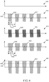
- the EAS tag reader 104 may transition from a mode in which it does not produce an EAS tag detection signal at all (e.g., as indicated by the absence of an EAS tag detection signal in graph 600, FIG. 6 ), to a mode in which it produces an EAS tag detection signal (e.g., a signal such as one of the EAS tag detection signals 612, 622, 632, 642 in graphs 610, 620, 630, 640, FIG. 6 ), in an embodiment.
- EAS tag reader 104 may transition from a mode in which it produces an EAS tag detection signal having first transmission characteristics (e.g., a first duty cycle, pulse frequency, and power, such as EAS tag detection signal 612 in graph 610, FIG.
- the second transmission characteristics may be selected to increase the probability of detecting an EAS tag within range of the EAS tag reader 104, when compared with the probability of detection using an EAS tag detection signal having the first transmission characteristics. For example, when compared with EAS tag detection signal 612 in graph 610, FIG. 6 , each of EAS tag detection signals 622, 632, 642 in graphs 620, 630, 640, FIG.
- EAS tag detection signal 6 may have a higher probability of detection, as they have a higher pulse frequency, higher duty cycle, and higher power, respectively, than EAS tag detection signal 612.
- the EAS tag signal produced in the second operational mode may have any combination of higher frequency, higher duty cycle, and power, in various embodiments.
- the overall power consumption of the EAS tag reader 104 may be significantly lower.
- the amount of power consumed by the EAS tag reader 104 is low while the EAS tag reader 104 is in the first operational mode, since either the EAS tag reader 104 is not producing an EAS tag detection signal at all or the EAS tag detection signal produced may be of relatively low power, when compared with the EAS tag detection signal produced while the EAS tag reader 104 is in the second operational mode.
- the EAS tag signal produced in the second operational mode not only may increase the probability of detection, but also may increase a range of detection by the EAS reader 104. Accordingly, such embodiments provide an "early warning" system that may enable detection of an EAS tag at a distance that is farther from a pedestal pair than is possible with conventional EAS tag detection techniques. More particularly, using an embodiment of the inventive subject matter, the system may produce an alarm to alert store personnel about the approach of an active EAS tag to a pedestal pair when the EAS tag is farther from the pedestal pair, and thus at a time that is earlier than a time that an alarm would be produced using conventional EAS tag detection techniques. Accordingly, store personnel may have more time to apprehend an individual carrying an active EAS tag toward an exit, thus improving loss prevention.
- the detection area for the EAS tag reader 104 is an area 140 proximate to the pedestal pair 108.
- the detection range of the proximity detection system 102 is significantly farther than the detection range of the EAS tag reader 104.
- the detection range of EAS tag reader 104 may be in a range of about 3 meters or less, and depending on the type of proximity detection employed by proximity detection system 102, the detection range of proximity detection system 102 may be in a range of about 10 to 50 meters.
- the detection ranges of EAS tag reader 104 and/or proximity detection system 102 may be larger or smaller than the above given values and ranges.
- the detection area 140 of EAS tag reader 104 may completely overlap the detection area 142 of proximity detection system 102, as shown in FIG. 1 .
- the detection areas 140, 142 may only partially overlap or may not overlap at all, depending on the configuration of the portal 130 and the placement of the transmit/receive antennas or sensor associated with the proximity detection system 102, with respect to the portal pair 108.
- the detection area 142 of proximity detection system 102 may be significantly larger than the detection area 140 of EAS tag reader 104. This enables the presence of an object 115-117 with which the EAS tag 112-114 is associated (e.g., attached) to be detected earlier than would be possible using only EAS tag reader 104. In addition, as will be explained in more detail later, this enables the EAS tag reader 104 to be operated in a less power consumptive mode in the absence of any detected object within area 142, while allowing a transition to operation in a more accurate detection mode in the presence of a detected object within area 142. As mentioned above, this enables the EAS tag reader 104 to be operated in a mode that increases the EAS tag detection area.
- an alarm produced upon detection of an active EAS tag may be produced earlier than it would be using a conventional EAS system, and store personnel or security staff may have more time to respond to the alarm (e.g., to apprehend an individual carrying the EAS tag before the individual exits the premises).
- EAS tag reader 104 is an acousto-magnetic EAS system
- a transmitter and transmit antenna (e.g., within transmit pedestal 109) of EAS tag reader 104 are configured to emit the EAS tag detection signal in the form of periodic activation pulses at a given frequency during an activation phase
- a receiver and receive antenna (e.g., within receive pedestal 110) of EAS tag reader 104 are configured to receive oscillating signals emitted from an EAS tag (e.g., EAS tag 112) in response to encountering activation pulses of sufficient power.
- the activation pulses energize the tag during the activation phase, and the tag continues to emit the oscillating signals even after the activation signal is discontinued.
- the oscillating signal produced by the tag induces an AC voltage in the receive antenna (e.g., within receive pedestal 110) of the EAS tag reader 104.
- the induced signal meets predefined detection parameters (e.g., the detected signal has a frequency of 58 kHz and is time-synchronized with the transmitter)
- the EAS tag reader 104 may produce a control signal, which causes alarm 106 to produce an audible alarm.
- object 115 may be considered to be within the detection range of both the proximity detection system 102 and the EAS reader 104 when object 115 (and EAS tag 112) are within area 140.
- EAS tag reader 104 is a swept RF EAS system
- a transmitter and transmit antenna (e.g., within transmit pedestal 109) of EAS tag reader 104 are configured to emit the EAS tag detection signal in the form of a relatively high-powered signal that sweeps around the pre-defined resonant frequency
- a receiver and receive antenna (e.g., within receive pedestal 110) of EAS tag reader 104 are configured to receive oscillating signals emitted from an EAS tag (e.g., EAS tag 112) in response to encountering activation pulses of sufficient power.
- the activation pulses energize the tag during the activation phase, and the tag continues to emit the oscillating signals even after the activation signal is discontinued.
- the oscillating signal produced by the tag induces an AC voltage in the receive antenna (e.g., within receive pedestal 110) of the EAS tag reader 104.
- the induced signal meets predefined detection parameters (e.g., the detected signal has a frequency of 58 kHz and is time-synchronized with the transmitter)
- the EAS tag reader 104 may produce a control signal, which causes alarm 106 to produce an audible alarm.
- object 115 may be considered to be within the detection range of both the proximity detection system 102 and the EAS reader 104 when object 115 (and EAS tag 112) are within area 140.
- Each EAS tag (e.g., EAS tag 112) includes circuitry with a resonance peak within a certain frequency range (e.g., from 1.75 to 9.5 MHz), with 8.2 MHz being preferred, in an embodiment), and an EAS tag responds to the swept RF signal produced by the transmitter by emitting a signal that may be detected by a wideband receiver of the EAS tag reader 104 when the EAS tag is within a detection zone 140 (e.g., an RF range of the detector).
- the EAS tag reader 104 detects a phase difference between the transmitted and received signals.
- the EAS tag reader 104 When the EAS tag reader 104 recognizes the presence of the EAS tag (e.g., EAS tag 112) within the detection zone 140, the EAS tag reader 104 may produce a control signal, which causes alarm 106 to produce an audible alarm.
- object 115 may be considered to be within the detection range of both the proximity detection system 102 and the EAS reader 104 when object 115 (and EAS tag 112) are within area 140.
- EAS tags 112-114 may be housed within a housing or container 118, 119, 120 of some type, according to various embodiments.
- EAS tags 112-114 may be housed in a relatively durable plastic housing, which may be adhered or otherwise attached to an object.
- objects 115-117 are RFID tags
- the RFID tags may be housed within the same housings or containers as the EAS tags 112-114, as shown in FIG. 1 .
- the RFID tags may be housed within different housings or containers from the EAS tags 112-114.
- a container 118-119 may be any one of a bag, a box, a package, a crate, a pallet, or another type of container.
- the RFID tags e.g., objects 115-117) may be integrally formed with or otherwise attached or integrated with container 118-119.
- EAS tags 112-114 also or alternatively may be integrally formed with or otherwise attached to or integrated with container 118-119.
- the retail store clerk may deactivate the RFID tags and EAS tags 112-114 by performing a deactivation process to a bag (e.g., a container 118-120) within which the store clerk will place the purchased article for presentation to the purchaser.
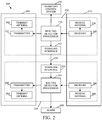
- FIG. 2 is a simplified block diagram of an EAS system 200, in accordance with an example embodiment. More particularly, the embodiment relates to an EAS system 200 that includes an RFID tag reader 202 as a proximity detection system (e.g., proximity detection system 102, FIG. 1 ), and the RFID tag reader 202 is implemented using distinct hardware from EAS tag reader 204 (e.g., EAS tag reader 104, FIG. 1 ).
- EAS system 200 includes the RFID tag reader 202, the EAS tag reader 204, an alarm 206, and a pedestal pair consisting of a transmit pedestal 209 and a receive pedestal 210.
- the RFID tag reader 202 may be communicatively coupled with an inventory control system 230.
- RFID tag reader 202 is configured to detect a presence of an RFID tag (e.g., object 115 or 116, FIG. 1 ) within a first detection area (e.g., area 142, FIG. 1 ), and to generate a proximity signal 232 in response to detecting the RFID tag within the first area.
- RFID tag reader 202 includes an RFID tag detection processor 240, a transmitter 242, a transmit antenna 244, a receiver 246, a receive antenna 248, and a signaling interface 250.
- the transmit antenna 244 (and possibly transmitter 242) may be housed within transmit pedestal 209, and the receive antenna 248 (and possibly receiver 246) may be housed within receive pedestal 210, although this is not a requirement. In an alternate embodiment, the transmit antenna 244 and/or receive antenna 248 may be located elsewhere.
- RFID tag detection processor 240 includes one or more general or special purpose processors and associated memory and other circuitry, which enables RFID tag detection processor 240 to execute an RFID tag detection algorithm.
- the particular RFID tag detection algorithm depends on the type of RFID tag employed in the system.
- the RFID tag detection algorithm is configured to communicate with an RFID tag selected from a group consisting of an active RFID tag, a passive RFID tag, and a battery-assist passive RFID tag.
- Each of these types of RFID tags includes an integrated circuit for storing information (e.g., an article identifier), processing RFID tag interrogation signals from RFID tag reader 202, and transmitting an RFID tag response signal that includes the stored information.
- An RFID tag also may be programmable to store the transaction status of an item (i.e., whether the item is "transacted” (paid-for and sold) or "non-transacted” (not yet paid for or sold)).
- the transaction status may be initialized to "non-transacted," and when the item is sold, equipment at the point-of-sale may be used to change the stored transaction status to "transacted.”
- An active RFID tag includes a battery, and is capable of transmitting a signal autonomously.
- a passive RFID tag does not include a battery, and requires an external source (e.g., RFID tag reader 202) to provoke signal detection.
- a battery-assisted passive RFID tag requires an external source to wake up, although it has a significant higher forward link capability, thus providing greater range.
- the RFID tag detection algorithm includes invoking the transmitter 242 and transmit antenna 244 to radiate an RFID tag interrogation signal, and evaluating signals received via receive antenna 248 and receiver 246 to determine whether they are valid RFID tag response signals. According to an embodiment, when a valid RFID tag interrogation signal is received, the RFID tag detection algorithm is configured to produce the proximity signal 232, which is communicated to the EAS tag detector 204 via signaling interface 250.
- the RFID tag detection algorithm is also configured to detect whether the responding RFID tag is in motion, although this is not a requirement.
- the RFID tag reader 202 may produce the proximity signal 232 only upon detecting that the RFID tag is in motion.
- the RFID tag reader 202 may produce the proximity signal 232 upon detecting that the RFID tag is in motion and the direction of motion is toward the portal (i.e., the RFID tag is approaching the portal, as opposed to moving away from the portal).
- EAS system 200 without causing the RFID tag reader 202 to send the proximity signal 232 and trigger the EAS tag reader 204 to change its mode of operation. Because a purpose of EAS system 200 is to detect potential theft of articles, it is desirable to detect EAS tags on articles that are in motion (e.g., being carried out of the retail store by a shoplifter), rather than to detect EAS tags on articles that are stationary (e.g., on display in proximity to a portal).
- the RFID tag detection algorithm is configured to provide information received in the RFID tag response signals to inventory control system 230 when an RFID tag associated with (e.g., attached to) a particular article has been detected in proximity to or passing through the portal (e.g., portal 130, FIG. 1 ), thus indicating that the article may be leaving a controlled area (e.g., a retail store). Accordingly, the RFID tag detection algorithm may not provide the information to the inventory control system 230 immediately upon detection of the RFID tag in the first detection area (e.g., area 142, FIG.
- the RFID tag detection algorithm may use RFID phase and signal strength measurements to determine motion of an RFID tag and its distance from the RFID tag reader 202 (e.g., its motion relative to and distance from the portal).
- the information received in an RFID tag response signal may include an article identifier (e.g., a SKU of an article to which the responding RFID tag is attached), and the RFID tag detection algorithm may send article-identity-indicating information that indicates the identity of the article to the inventory control system 230, when it is determined that the RFID tag is in proximity to, approaching, is passing through, or has passed through the portal.
- an article identifier e.g., a SKU of an article to which the responding RFID tag is attached
- the RFID tag detection algorithm may send article-identity-indicating information that indicates the identity of the article to the inventory control system 230, when it is determined that the RFID tag is in proximity to, approaching, is passing through, or has passed through the portal.
- the information received in an RFID tag response signal may include the stored transaction status of the item (e.g., transacted or non-transacted), and the RFID tag detection algorithm may indicate to the inventory control system 230 whether or not the article was properly purchased.
- the RFID tag reader 202 may report to the inventory control system 230 the transaction status stored in the RFID tag.
- the inventory control system 240 may cause a display (e.g., at a point-of-sale, office or other area) to display an alert, an image of a non-transacted item, and/or the article identifier (e.g., the SKU) associated with the RFID tag.
- the displayed alert alternatively may be initiated by the RFID tag reader 202. Either way, the displayed alert may apprise store and/or security personnel of a potential theft, and the personnel may implement responsive actions.
- the RFID tag reader 202 may provide the transaction status information to the inventory control system 230, and the RFID tag reader 202 or inventory control system 230 may cause the alert/image/identifier to be displayed while the non-transacted RFID tag and article are located within either area 142 or within area 140.
- the report is produced by the RFID tag reader 202 and the alert/image/identifier is displayed while the non-transacted RFID tag is outside of area 140, but within area 142, enables store and/or security personnel to be alerted of a potential theft well in advance of the non-transacted RFID tag entering area 140, when it may be too late to respond.
- Inventory control system 230 is configured to maintain inventory information regarding quantities of a plurality of articles that are present within a controlled area at which the EAS system 200 is installed (e.g., a retail store). In response to receiving article-identity-indicating information from the RFID tag reader 202 (and possibly the transaction status of the associated article), the inventory control system 230 may update the inventory information regarding a quantity of the article present in the controlled area, in an embodiment.
- EAS tag reader 204 is configured to detect a presence of an EAS tag (e.g., EAS tag 112, FIG. 1 ) within a second detection area (e.g., area 140, FIG. 1 ) by producing an EAS tag energizing signal, and detecting an appropriate response from the EAS tag.
- EAS tag reader 204 is configured to receive the proximity signal 232 from the RFID tag reader 202, and to alter characteristics of an EAS tag energizing signal in response to receiving the proximity signal.
- EAS tag reader 204 includes an EAS tag detection processor 260, a transmitter 262, a transmit antenna 264, a receiver 266, a receive antenna 268, and signaling interface 270.
- the transmit antenna 264 (and possibly transmitter 262) are housed within transmit pedestal 209, and the receive antenna 268 (and possibly receiver 266) may be housed within receive pedestal 210.
- EAS tag detection processor 260 includes one or more general or special purpose processors and associated memory and other circuitry, which enables EAS tag detection processor 260 to execute an EAS tag detection algorithm.
- the EAS tag detection algorithm includes invoking the transmitter 262 and transmit antenna 264 to radiate an EAS tag detection signal, and evaluating signals received via receive antenna 268 and receiver 266 to determine whether they are valid EAS tag response signals.
- EAS tag detection processor 260 produces a control signal, which causes alarm 206 to produce an audible alarm.
- the RFID tag reader 202 or the inventory control system 230 may provide an alarm control signal to alarm 206 when a determination has been made that a non-transacted item is in proximity to, is approaching, is passing through, or has passed through the portal, as discussed previously.
- Alarm control signals from RFID tag reader 202 may be provided directly to alarm 206, for example, and alarm control signals from inventory control system 230 may be provided directly to alarm 206 or may be communicated through RFID tag reader 202 and/or EAS tag reader 204, in various embodiments.
- the EAS tag reader 204 may operate in at least two operational modes. In a first operational mode, the EAS tag reader 204 either bypasses production of the EAS tag detection signal or generates the EAS tag detection signal with first transmission characteristics, in various embodiments. When the EAS tag reader 204 receives the proximity signal 232 from the RFID tag reader 202 via signaling interface 270, the EAS tag reader 204 transitions to a second operational mode. In the second operational mode, the EAS tag reader 204 initiates production of the EAS tag detection signal (i.e., if the first operational mode involved not transmitting the EAS tag detection signal), or beginning to transmit the EAS tag detection signal with second and different transmission characteristics, in various embodiments. Transition between the various operational modes will be discussed in more detail later.
- FIG. 3 is a simplified block diagram of an EAS system 300, in accordance with another example embodiment.
- EAS system 300 includes an RFID/EAS tag detection processor 340, an alarm 306, and a pedestal pair consisting of a transmit pedestal 309 and a receive pedestal 310.
- RFID/EAS tag detection processor 340 may be communicatively coupled with an inventory control system 330.
- RFID/EAS tag detection processor 340 includes one or more general or special purpose processors and associated memory and other circuitry, which enables RFID/EAS tag detection processor 340 to execute an RFID tag detection algorithm and an EAS tag detection algorithm, as discussed previously, or a single algorithm that includes the capabilities of both the RFID tag detection algorithm and the EAS tag detection algorithm, as discussed previously. These algorithms will be referred to collectively as an RFID/EAS tag detection algorithm.
- RFID/EAS tag detection processor 340 By executing the RFID tag detection algorithm, RFID/EAS tag detection processor 340, in conjunction with transmitter 342, transmit antenna 344, receiver 346, and receive antenna 348, is configured to detect a presence of an RFID tag (e.g., object 115 or 116, FIG. 1 ) within a first detection area (e.g., area 142, FIG. 1 ), as discussed previously.
- the RFID/EAS tag detection processor 340 may communicate article-identity-indicating information to the inventory control system 330 upon detection of an RFID tag exiting a controlled area, as discussed previously.
- RFID/EAS tag detection processor 340 in conjunction with transmitter 342, transmit antenna 344, receiver 346, and receive antenna 348, is configured to detect a presence of an EAS tag (e.g., EAS tag 112, FIG. 1 ) within a second detection area (e.g., area 140, FIG. 1 ).
- EAS tag e.g., EAS tag 112, FIG. 1
- RFID/EAS tag detection processor 340 produces a control signal, which causes alarm 306 to produce an audible alarm.
- the transmit antenna 344 (and possibly transmitter 342) may be housed within transmit pedestal 309, and the receive antenna 348 (and possibly receiver 346) may be housed within receive pedestal 310.
- the RFID tag detection algorithm and the EAS tag detection algorithm share the same transmitter 342, transmit antenna 344, receiver 346, and receive antenna 348, as shown in FIG. 3 , the transmitter 342 should be capable of modulating signals in frequency ranges pertinent to both RFID tag detection and EAS tag detection, and the receiver 346 should be capable of demodulating signals in the RFID tag detection and EAS tag detection ranges, as well.
- the RFID/EAS tag detection algorithm may be executed on a single processor, separate transmitters, transmit antennas, receivers, and receive antennas may be used for sending and receiving signals from the RFID and EAS tags (e.g., as implemented in the system of FIG. 1 ).
- FIG. 4 is a simplified block diagram of an EAS system 400 in which proximity detection is performed using a sensor-based system (rather than an RFID tag reader), in accordance with yet another example embodiment.
- EAS system 400 includes a sensor system 430, an EAS tag detection processor 440, an alarm 406, and a pedestal pair consisting of a transmit pedestal 409 and a receive pedestal 410.
- the transmit antenna 444 (and possibly transmitter 442) may be housed within transmit pedestal 409, and the receive antenna 448 (and possibly receiver 446) may be housed within receive pedestal 410.
- Sensor system 430 may include any one or more types of sensors selected from a group consisting of a camera, optical sensor, and/or laser, which enable detection of the entry, presence, and/or movement of an object (e.g., object 116, 117, FIG. 1 ) within a first detection area (e.g., area 142, FIG. 1 ).
- the raw data produced by the sensor may be provided to EAS tag detection processor 440 for analysis of whether an object has entered, is present within, or is moving within the first detection area.
- the sensor system 430 may analyze the raw data produced by the sensor to detect the entry, presence, and/or movement of an object within the first detection area, and when such a detection is made, the sensor system 430 may send a proximity signal 432 to EAS tag detection processor 440.
- EAS tag detection processor 440 includes one or more general or special purpose processors and associated memory and other circuitry, which enables EAS tag detection processor 440 to execute an EAS tag detection algorithm, as discussed previously. By executing the EAS tag detection algorithm, and in response to detecting the presence and/or movement of the object within the first detection area, EAS tag detection processor 440, in conjunction with transmitter 442, transmit antenna 444, receiver 446, and receive antenna 448, is configured to detect a presence of an EAS tag (e.g., EAS tag 112, FIG. 1 ) within a second detection area (e.g., area 140, FIG. 1 ). When an EAS tag is detected within the second detection area, RFID/EAS tag detection processor 440 produces a control signal, which causes alarm 406 to produce an audible alarm.
- EAS tag detection processor 440 in conjunction with transmitter 442, transmit antenna 444, receiver 446, and receive antenna 448, is configured to detect a presence of an EAS tag (e.g., EAS tag 112, FIG. 1
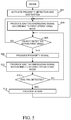
- FIG. 5 is a flowchart of a method for performing tag proximity detection and EAS, in accordance with an example embodiment.
- the method begins, in block 502, when the proximity detection and EAS system is activated. Activation may include, for example, powering up the proximity detection and EAS system (e.g., system 100, FIG. 1 ), and waiting for the system to perform various bootup and initialization algorithms in order to reach an operational state.
- Activation may include, for example, powering up the proximity detection and EAS system (e.g., system 100, FIG. 1 ), and waiting for the system to perform various bootup and initialization algorithms in order to reach an operational state.
- an EAS tag reader begins operation in a first operational mode.
- the EAS tag reader bypasses production of an EAS tag detection signal.
- FIG. 6 which illustrates EAS tag detection signals produced by the EAS tag reader in first and second operational modes, in accordance with various example embodiments, bypassing production of the EAS tag detection signal indicated by the absence of an EAS tag detection signal in graph 600, as discussed previously.
- the EAS tag reader in the first operational mode, produces an EAS tag detection signal having first transmission characteristics, such as EAS tag detection signal 612 in graph 610.
- EAS tag detection signal 612 is characterized by a duty cycle determined by the ratio of the duration 614 of each transmit pulse 616 to the time 618 between transmit pulses 616.
- EAS tag detection signal 612 is characterized by a pulse frequency (e.g., in a range of about 20 to 58 kHz, or some other value) and a pulse power level 619.
- a determination is made whether an object is detected within a first detection area (e.g., area 142, FIG. 1 ).
- this determination may be made by any of a variety of proximity detection systems, including but not limited to an RFID tag reader (i.e., when the "object" is an RFID tag), a camera, an optical sensor, and a laser system, to name a few.
- an RFID tag reader i.e., when the "object" is an RFID tag
- the method iterates as shown, and the EAS tag reader remains in the first operational mode.
- a proximity signal e.g., proximity signal 232 or 432, FIGs. 2 , 4
- optionally may be produced, in block 508.
- the proximity signal may be produced by the proximity detection system to inform the EAS tag reader that the object has been detected.
- the proximity detection and EAS tag detection are performed using shared hardware (e.g., as in system 300, FIG. 3 )
- the proximity signal need not be produced, and detection of the object may result in a branch in an algorithm (e.g., an EAS tag detection algorithm).
- the EAS tag reader transitions to operation in a second operational mode in response to receipt of the proximity signal or merely in response to the detection of the object within the first detection area.
- transition to the second operational mode includes the EAS tag reader initiating production of an EAS tag detection signal.
- the EAS tag reader may produce an EAS tag detection signal having particular transmission characteristics (e.g., any one of the EAS tag detection signals 612, 622, 632, 642 in graphs 610, 620, 630, 640).
- transition to the second operational mode includes the EAS tag reader initiating production of an EAS tag detection signal having different transmission characteristics from the EAS tag detection signal transmitted while in the first operational mode.
- the EAS tag reader may transition from transmitting an EAS tag detection signal such as signal 612 with a first duty cycle, first frequency, and first power 619 to transmitting an EAS tag detection signal such as signal 622 (which has a higher pulse frequency), signal 632 (which has a longer duty cycle as indicated by the longer duration 634 of transmit pulses 636 relative to the time 638 between pulses 636), or signal 642 (which has a higher pulse power level 646 than the pulse power level 619 of EAS tag detection signal 612).
- an EAS tag detection signal such as signal 612 with a first duty cycle, first frequency, and first power 619
- an EAS tag detection signal such as signal 622 (which has a higher pulse frequency)
- signal 632 which has a longer duty cycle as indicated by the longer duration 634 of transmit pulses 636 relative to the time 638 between pulses 636
- signal 642 which has a higher pulse power level 646 than the pulse power level 619 of EAS tag detection signal 612).
- the EAS tag detection signal transmitted in conjunction with the second operational mode may have only a single different transmit signal characteristic (e.g., only the duty cycle, pulse frequency or pulse power level is different), the EAS tag detection signal alternatively may have more than one different transmit signal characteristic, as well.
- the characteristics of the EAS tag detection signal transmitted in conjunction with the second operational mode are selected to increase the probability of detecting an EAS tag within range of the EAS tag reader, when compared with the probability of detection using an EAS tag detection signal having the first transmission characteristics.
- this determination is made during a detection phase (e.g., when the EAS tag reader is not generating an EAS tag detection signal).
- an EAS tag may be considered to have been detected when a signal produced by an EAS tag and received by the EAS tag reader meets predefined detection parameters (e.g., the detected signal has an appropriate frequency and is time-synchronized with the transmitter).
- the method iterates as shown, and the EAS tag reader either remains in the second operational mode (while achieving regulatory compliance and while the object continues to be detected within the first detection area) or transitions back to the first operational mode (when the object is no longer detected within the first detection area).
- the EAS system may produce an audible alarm, in block 514. The method may then iterate as shown.
- FIG. 5 depicts a method for detecting proximity of an object and EAS tag that may utilize any of a variety of proximity detection techniques. As discussed in detail above, one such proximity detection technique is detection of the proximity of an RFID tag.
- FIG. 7 is a flowchart of a method for detecting proximity of an RFID tag and an EAS tag, in accordance with an example embodiment. The method of FIG. 7 has some similarities to the method of FIG. 5 , with distinctions called out in more detail below.
- the method begins, in block 702, when the proximity detection and EAS system is activated. Activation may include, for example, powering up the proximity detection and EAS system (e.g., system 100, FIG. 1 ), and waiting for the system to perform various bootup and initialization algorithms in order to reach an operational state.
- an EAS tag reader e.g., EAS tag reader 104, FIG. 1
- the EAS tag reader bypasses production of an EAS tag detection signal.
- the EAS tag reader produces an EAS tag detection signal having first transmission characteristics.
- an RFID tag reader e.g., RFID tag reader 202, FIG. 2
- a proximity signal (e.g., proximity signal 232, FIG. 2 ) optionally may be produced, in block 710.
- the proximity signal may be produced by the RFID tag reader to inform the EAS tag reader that the RFID tag has been detected.
- the RFID tag detection and EAS tag detection are performed using shared hardware (e.g., as in system 300, FIG. 3 )
- the proximity signal need not be produced, and detection of the RFID tag may result in a branch in an algorithm (e.g., an EAS tag detection algorithm).
- the RFID tag reader may communicate article-identity-indicating information to an inventory control system (e.g., inventory control system 230, 330, FIGs. 2 , 3 ), when the RFID tag reader determines that the RFID tag has exited a controlled area (e.g., a retail store).
- a controlled area e.g., a retail store.
- the inventory control system may use the article-identity-indicating information to update inventory information regarding the quantity of the article within the controlled area, in an embodiment.
- the RFID tag reader may receive an indication from the RFID tag of a transaction status of the RFID tag (e.g., whether the RFID tag has a stored transaction status of "transacted" or "non-transacted"), and the RFID tag reader may provide the indication to the inventory control system.
- the inventory control system may cause an alert or an alarm to be produced.
- the RFID tag reader may cause an alert or an alarm to be produced when the transaction status is non-transacted.
- the EAS tag reader transitions to operation in a second operational mode in response to receipt of the proximity signal or merely in response to the detection of the RFID tag within the first detection area.
- transition to the second operational mode includes the EAS tag reader initiating production of an EAS tag detection signal.
- transition to the second operational mode includes the EAS tag reader initiating production of an EAS tag detection signal having different transmission characteristics from the EAS tag detection signal transmitted while in the first operational mode.
- the method iterates as shown, and the EAS tag reader either remains in the second operational mode (while achieving regulatory compliance and while the RFID tag continues to be detected within the first detection area) or transitions back to the first operational mode (when the RFID tag is no longer detected within the first detection area).
- the EAS system may produce an audible alarm, in block 718. The method may then iterate as shown.
- the RFID tag detection system may be operatively coupled with an inventory control system (e.g., inventory control system 230, 330, FIGs. 2 , 3 ).
- the RFID tag reader may communicate article-identity-indicating information to the inventory control system, which indicates the identity of an article to which a detected RFID tag is attached, and the inventory control system may update inventory information regarding the quantity of the article in the retail store, accordingly.
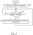
- FIG. 8 is a flowchart of a method for updating inventory information, in accordance with an example embodiment.
- the method may be performed, for example, by an inventory control system (e.g., inventory control system 230, 330, FIGs 2 , 3 ) that is communicatively coupled with an RFID tag reader.
- the method begins, in block 802, by maintaining inventory information for one or more articles (e.g., articles that may be identified, for example, by a unique SKU).
- the inventory information may reflect, for example, how many of each article are present within a controlled area (e.g., a retail store).
- the message may include article-identity-indicating information derived from an RFID tag response signal.
- the article-identity-indicating information may be a value that actually identifies the article (e.g., a unique SKU) or a value that may be correlated with other information to derive the identity of the article.
- the method iterates as shown.
- inventory information regarding a quantity of the article may be updated, in block 806. According to an embodiment, this may include decrementing a current quantity of the item by one, for example. The method then iterates as shown.
- An embodiment includes a reader system comprising a proximity sensor system and an EAS tag reader, communicatively coupled to the proximity sensor system.
- the proximity sensor system is configured to detect a presence of an object within a first area, and to generate a proximity signal in response to detecting the object within the first area.
- the EAS tag reader is configured to make a transition from a first operational mode to a second operational mode in response to receiving the proximity signal from the proximity sensor system. The transition includes the EAS tag reader altering production of an EAS tag detection signal.
- Another embodiment includes a reader system comprising an RFID tag reader and an EAS tag reader communicatively coupled to the RFID tag reader.
- the RFID tag reader is configured to detect a presence of an RFID tag within a first area, and to generate a proximity signal in response to detecting the RFID tag within the first area.
- the EAS tag reader is configured to detect a presence of an EAS tag within a second area by producing an EAS tag detection signal.
- the EAS tag reader is further configured to alter characteristics of the EAS tag detection signal in response to receiving the proximity signal from the RFID tag reader.
- Yet another embodiment includes a reader system comprising a processing system and an RF system operably coupled with the processing system.
- the processing system is configured to detect a presence of an object using an object detection technique other than EAS, and to make a transition from a first operational mode to a second operational mode in response to detecting the presence of the object.
- the transition includes altering production of an EAS tag detection signal.
- the RF system is configured to radiate the EAS tag detection signal.
- Yet another embodiment includes a method for detecting proximity of an EAS tag.
- the method comprises the steps of detecting, by a proximity detection system, a presence of an object within a first area, and altering characteristics of an EAS tag detection signal that is produced by an EAS tag reader in response to detecting the proximity of the object.
Landscapes
- Physics & Mathematics (AREA)
- Engineering & Computer Science (AREA)
- General Physics & Mathematics (AREA)
- Automation & Control Theory (AREA)
- Computer Security & Cryptography (AREA)
- Electromagnetism (AREA)
- Business, Economics & Management (AREA)
- Economics (AREA)
- Multimedia (AREA)
- Entrepreneurship & Innovation (AREA)
- Development Economics (AREA)
- Human Resources & Organizations (AREA)
- Marketing (AREA)
- Operations Research (AREA)
- Quality & Reliability (AREA)
- Strategic Management (AREA)
- Tourism & Hospitality (AREA)
- General Business, Economics & Management (AREA)
- Theoretical Computer Science (AREA)
- Burglar Alarm Systems (AREA)
Claims (5)
- Lesesystem (100), das Folgendes umfasst:ein Näherungssensorsystem (102), das konfiguriert ist, um eine Anwesenheit eines Gegenstands (115, 116, 117) innerhalb eines ersten Bereichs (142) zu erfassen und ein Näherungssignal als Reaktion auf ein Erfassen des Gegenstands innerhalb des ersten Bereichs zu erzeugen; undeinen Etikettenleser (104) mit elektronischer Artikelsicherung (EAS), der kommunikativ an das Näherungssensorsystem gekoppelt und konfiguriert ist, um von einem ersten Betriebsmodus zu einem zweiten Betriebsmodus als Reaktion auf ein Empfangen des Näherungssignals von dem Näherungssensorsystem überzugehen, wobei der Übergang eine sich ändernde Produktion eines EAS-Etiketten-Erfassungssignals des Etikettenlesers mit EAS aufweist, wobei der Etikettenleser mit EAS konfiguriert ist, um Merkmale des EAS-Etiketten-Erfassungssignals durch ein Übergehen von einem Überhaupt-Nicht-Produzieren eines EAS-Etiketten-Erfassungssignals in dem ersten Betriebsmodus zu einem Produzieren des EAS-Etiketten-Erfassungssignals in dem zweiten Betriebsmodus zu ändern.
- Lesesystem nach Anspruch 1, wobei das Näherungssensorsystem einen Etikettenleser (202) mit Radiofrequenzidentifikation (RFID) umfasst, und das Lesesystem ferner Folgendes umfasst:den Gegenstand in einer Form einer RFID-Etikette, die konfiguriert ist, um mit dem Etikettenleser mit RFID in Wechselwirkung zu treten, um den Etikettenleser mit RFID zu befähigen zu bestimmen, ob die Etikette mit RFID innerhalb des ersten Bereichs ist, wobei der erste Bereich einem RF-Bereich des Etikettenlesers mit RFID entspricht; undeine Etikette mit EAS (112, 113, 114), die konfiguriert ist, um mit dem Etikettenleser mit EAS durch Reagieren auf das EAS-Etiketten-Erfassungssignal in Wechselwirkung zu treten, wodurch der Etikettenleser mit EAS befähigt wird zu bestimmen, ob die Etikette mit EAS (112, 113, 114) innerhalb eines zweiten Bereichs ist, wobei der zweite Bereich einem RF-Bereich des Etikettenlesers mit EAS entspricht.
- Verfahren zum Erfassen einer Näherung einer Etikette mit elektronischer Artikelsicherung (EAS), wobei das Verfahren die folgenden Schritte umfasst:Erfassen einer Anwesenheit eines Gegenstands innerhalb eines ersten Bereichs durch ein Näherungserfassungssystem;Erzeugen eines Näherungssignals durch das Näherungserfassungssystem als Reaktion auf ein Erfassen des Gegenstands innerhalb des ersten Bereichs;Empfangen des Näherungssignals durch den Etikettenleser mit EAS, wobei der Etikettenleser mit EAS die Merkmale eines EAS-Etiketten-Erfassungssignals ändert, das durch einen Etikettenleser mit EAS als Reaktion auf ein Erfassen der Näherung des Gegenstands produziert wird,wobei der Schritt des Änderns der Merkmale des EAS-Etiketten-Erfassungssignals ein Übergehen von einem ersten Betriebsmodus, in dem das EAS-Etiketten-Erfassungssignal überhaupt nicht produziert wird, zu einem zweiten Betriebsmodus, in dem das EAS-Etiketten-Erfassungssignal produziert wird, aufweist.
- Verfahren nach Anspruch 3, wobei das Näherungserfassungssystem einen Etikettenleser mit Radiofrequenzidentifikation (RIFD) umfasst und das Verfahren ferner die folgenden Schritte umfasst:Empfangen einer Anzeige durch den Etikettenleser mit RFID von der Etikette mit RFID eines Transaktionsstatus der Etikette mit RFID; undwenn der Transaktionsstatus nicht durchgeführt ist, verursacht der Etikettenleser mit RFID eine Warnung oder einen Alarm, die zu produzieren sind.
- Verfahren nach Anspruch 4, das ferner die folgenden Schritte umfasst:Erfassen, ob die Etikette mit RFID in Bewegung ist, durch den Etikettenleser mit RFID;Erzeugen eines Näherungssignals durch den Etikettenleser mit RFID als Reaktion auf ein Erfassen der Etikette mit RFID innerhalb des ersten Bereichs und ein Erfassen, dass die Etikette mit RFID in Bewegung ist; undEmpfangen des Näherungssignals durch den Etikettenleser mit EAS, wobei der Etikettenleser mit EAS die Merkmale des EAS-Etiketten-Erfassungssignals als Reaktion auf ein Empfangen des Näherungssignals ändert.
Applications Claiming Priority (2)
| Application Number | Priority Date | Filing Date | Title |
|---|---|---|---|
| US12/860,673 US8587432B2 (en) | 2010-08-20 | 2010-08-20 | Electronic article surveillance systems, apparatus, and methods |
| PCT/US2010/062623 WO2012023958A1 (en) | 2010-08-20 | 2010-12-31 | Electronic article surveillance systems, apparatus, and methods |
Publications (2)
| Publication Number | Publication Date |
|---|---|
| EP2606478A1 EP2606478A1 (de) | 2013-06-26 |
| EP2606478B1 true EP2606478B1 (de) | 2017-10-18 |
Family
ID=43977993
Family Applications (1)
| Application Number | Title | Priority Date | Filing Date |
|---|---|---|---|
| EP10814754.7A Active EP2606478B1 (de) | 2010-08-20 | 2010-12-31 | Systeme, vorrichtung und verfahren zur überwachung elektronischer artikel |
Country Status (3)
| Country | Link |
|---|---|
| US (2) | US8587432B2 (de) |
| EP (1) | EP2606478B1 (de) |
| WO (1) | WO2012023958A1 (de) |
Cited By (1)
| Publication number | Priority date | Publication date | Assignee | Title |
|---|---|---|---|---|
| US11195074B2 (en) | 2019-03-05 | 2021-12-07 | The Procter & Gamble Company | Wireless measurement of human product interaction |
Families Citing this family (45)
| Publication number | Priority date | Publication date | Assignee | Title |
|---|---|---|---|---|
| KR100788003B1 (ko) * | 2006-12-22 | 2007-12-21 | 주식회사 지오다이스 | 고유 타석 및 사용자 인증을 이용한 골프 레슨 장치 및서버 |
| FI124722B (fi) * | 2011-03-24 | 2014-12-31 | Nordic Id Oy | Lukijan käsittävä laite ja menetelmä lukijan toiminnan ohjaamiseksi |
| WO2013131084A1 (en) * | 2012-03-02 | 2013-09-06 | Rf Code, Inc. | Real-time asset tracking and event association |
| EP2862152A1 (de) * | 2012-06-18 | 2015-04-22 | RFID Resolution Team, Inc. | Elektronische artikelüberwachung mittels rfid |
| US9892289B2 (en) | 2012-12-07 | 2018-02-13 | Hand Held Products, Inc. | Reading RFID tags in defined spatial locations |
| WO2014169030A2 (en) * | 2013-04-12 | 2014-10-16 | Invue Security Products Inc. | Near field communication security devices |
| US9594939B2 (en) | 2013-09-09 | 2017-03-14 | Hand Held Products, Inc. | Initial point establishment using an image of a portion of an object |
| US9928672B2 (en) | 2013-12-05 | 2018-03-27 | Wallflower Labs Inc. | System and method of monitoring and controlling appliances and powered devices using radio-enabled proximity sensing |
| US9495569B2 (en) * | 2013-12-20 | 2016-11-15 | General Electric Company | System and method to detect an event associated with a person relative to a bed |
| JP6134262B2 (ja) * | 2013-12-27 | 2017-05-24 | 東芝テック株式会社 | 商品情報入力装置、システムおよびプログラム |
| EP2927838B1 (de) * | 2014-04-02 | 2016-03-16 | Sick Ag | Vorrichtung und Verfahren zum Identifizieren und Lokalisieren von Objekten |
| US20150287304A1 (en) * | 2014-04-07 | 2015-10-08 | Southern Imperial, Inc. | Identification Capturing Security Gate |
| WO2016022313A1 (en) * | 2014-08-05 | 2016-02-11 | Tyco Fire & Security Gmbh | Systems and methods for adaptively controlling a transmitter field |
| US9311796B2 (en) | 2014-08-22 | 2016-04-12 | Tyco Fire & Security Gmbh | Systems and methods for adaptively controlling a transmitter field |
| US9582976B2 (en) * | 2014-10-16 | 2017-02-28 | Elwha Llc | Systems and methods for detecting and reporting hazards on a pathway |
| US10049831B2 (en) * | 2015-09-29 | 2018-08-14 | Datalogic Ip Tech S.R.L. | Modular trigger assembly |
| US10081106B2 (en) | 2015-11-24 | 2018-09-25 | X Development Llc | Safety system for integrated human/robotic environments |
| RU2015153270A (ru) * | 2015-12-11 | 2017-06-16 | Константин МАРКАРЯН | Способ и устройство для мониторинга, предназначенные для мониторинга метки |
| US10186125B2 (en) * | 2015-12-18 | 2019-01-22 | Sensormatic Electronics, LLC | Systems and methods for tracking items removed without authorization from secured locations |
| DE102016114182B4 (de) * | 2016-08-01 | 2023-06-15 | Tdk-Micronas Gmbh | Fördereinrichtung und Verfahren zur Beförderung eines Gegenstandes |
| US11213773B2 (en) | 2017-03-06 | 2022-01-04 | Cummins Filtration Ip, Inc. | Genuine filter recognition with filter monitoring system |
| US10157337B1 (en) * | 2017-06-16 | 2018-12-18 | Amazon Technologies, Inc. | Pre-notification with RFID dock door portals |
| US20190035104A1 (en) * | 2017-07-25 | 2019-01-31 | Motionloft, Inc. | Object detection and tracking |
| WO2019204191A1 (en) | 2018-04-20 | 2019-10-24 | Walmart Apollo, Llc | Systems and methods of establishing rfid null zones in detecting products in a retail environment |
| EP3954053A1 (de) * | 2019-04-11 | 2022-02-16 | Nexite Ltd. | Drahtloses dual-modus-identifikationsetikett |
| US20210012622A1 (en) * | 2019-07-11 | 2021-01-14 | Zebra Technologies Corporation | Scanning Devices and Methods to Constrain Radio Frequency Identification (RFID) Signals Within a Physical Location |
| JP6835420B2 (ja) * | 2019-08-21 | 2021-02-24 | Necプラットフォームズ株式会社 | 情報処理装置、読取システム、情報処理方法、及びプログラム |
| US11348426B2 (en) * | 2019-08-30 | 2022-05-31 | Sensormatic Electronics, LLC | Radio frequency identification (RFID) tag location verification using image data |
| US12272221B2 (en) | 2019-08-30 | 2025-04-08 | Sensormatic Electronics, LLC | Radio frequency identification (RFID) tag location verification using acousto-magnetic detection |
| US11308780B2 (en) * | 2019-08-30 | 2022-04-19 | Sensormatic Electronics, LLC | Radio frequency identification (RFID) tag location verification using acousto-magnetic detection |
| US11688258B2 (en) | 2019-08-30 | 2023-06-27 | Sensormatic Electronics, LLC | Radio frequency identification (RFID) tag location verification using short range communication |
| US11436420B2 (en) * | 2019-09-06 | 2022-09-06 | Sensormatic Electronics, LLC | Increased power tag read cycle |
| US11315409B2 (en) * | 2019-09-18 | 2022-04-26 | Sensormatic Electronics, LLC | Decreasing false alarms in RFID exit portals |
| US11676462B2 (en) * | 2019-09-30 | 2023-06-13 | Sensormatic Electronics, LLC | Validating radio frequency identification (RFID) alarm event tags |
| US11423751B2 (en) * | 2019-10-14 | 2022-08-23 | Sensormatic Electronics, LLC | Validating radio frequency identification (RFID) tag alarm events |
| US11735019B2 (en) * | 2020-01-31 | 2023-08-22 | Sensormatic Electronics, LLC | System and method for increased exit interrogation of RFID tags |
| US12159521B2 (en) * | 2020-02-06 | 2024-12-03 | Avery Dennison Retail Information Services Llc | Control of RFID devices for increased reliability and effectiveness in an RFID electronic article surveillance system |
| EP4100931A1 (de) * | 2020-02-06 | 2022-12-14 | Avery Dennison Retail Information Services LLC | Modifikation von triggerschwellen von rfid-vorrichtungen in einem elektronischen artikelüberwachungssystem |
| EP4111431B1 (de) * | 2020-02-25 | 2024-07-24 | Avery Dennison Retail Information Services LLC | Konvergenz der leistung von rfid-vorrichtungen in einem elektronischen artikelüberwachungssystem |
| US12249225B2 (en) * | 2020-02-25 | 2025-03-11 | Avery Dennison Retail Information Services Llc | Range discrimination in an RFID electronic article surveillance system |
| JP7591955B2 (ja) * | 2021-03-15 | 2024-11-29 | 東芝テック株式会社 | 情報処理装置、プログラム及び情報処理システム |
| EP4473460A4 (de) * | 2022-01-31 | 2025-07-16 | Automaton Inc | Zustandsbehafteter inventar zur überwachung von rfid-etiketten |
| US12462662B2 (en) * | 2022-11-17 | 2025-11-04 | Zebra Technologies Corporation | Radio frequency proximity detection devices |
| WO2025231684A1 (en) * | 2024-05-09 | 2025-11-13 | Qualcomm Incorporated | Multi-round based proximity determination for the ambient-iot device |
| CN119903860B (zh) * | 2025-03-28 | 2025-09-16 | 支付宝(杭州)信息技术有限公司 | 一种信号调节单元以及读卡器设备 |
Family Cites Families (18)
| Publication number | Priority date | Publication date | Assignee | Title |
|---|---|---|---|---|
| US7081815B2 (en) * | 2001-08-23 | 2006-07-25 | Battelle Memorial Institute | Radio frequency security system, method for a building facility or the like, and apparatus and methods for remotely monitoring the status of fire extinguishers |
| US7527198B2 (en) * | 2002-03-18 | 2009-05-05 | Datalogic Scanning, Inc. | Operation monitoring and enhanced host communications in systems employing electronic article surveillance and RFID tags |
| US6752837B2 (en) * | 2002-06-28 | 2004-06-22 | Hewlett-Packard Development Company, L.P. | Security tags with a reversible optical indicator |
| US7042359B2 (en) * | 2003-08-23 | 2006-05-09 | Sensormatic Electronics Corporation | Method and apparatus to detect a plurality of security tags |
| US7804410B2 (en) | 2004-11-15 | 2010-09-28 | Sensormatic Electronics, LLC | Combination EAS and RFID label or tag |
| AU2005307719B2 (en) | 2004-11-18 | 2009-08-20 | Sensormatic Electronics Llc | EAS reader detecting EAS function from RFID device |
| US20070046470A1 (en) | 2005-08-29 | 2007-03-01 | Mark Pempsell | Hybrid Acousto-Magnetic Radio Frequency Transceiver Device |
| US20070126555A1 (en) | 2005-12-06 | 2007-06-07 | Symbol Technologies, Inc. | Method and system for optimizing radio frequency identification (RFID) reader operation |
| US8115600B2 (en) | 2008-11-19 | 2012-02-14 | Greatbatch Ltd. | RFID detection and identification system including an RFID reader having a limited transmit time and a time-out period to protect a medical device against RFID-associated electromagnetic interference |
| US20070200712A1 (en) | 2006-02-28 | 2007-08-30 | Symbol Technologies, Inc. | Smart RFID reader antennas |
| US20080136635A1 (en) | 2006-12-08 | 2008-06-12 | Symbol Technologies, Inc. | Low power rfid reader that gives visibility to passive tags as active tags using low power 802.11 |
| US20080266101A1 (en) * | 2007-04-27 | 2008-10-30 | Sensormatic Electronics Corporation | Security tag sensor and seccurity meethod for capital assets |
| US7619524B2 (en) | 2007-07-20 | 2009-11-17 | Symbol Technologies, Inc. | Identifying RFID tag moving coherently with reader |
| US8773266B2 (en) | 2007-11-16 | 2014-07-08 | Intermec Ip Corp. | RFID tag reader station with image capabilities |
| US7986241B2 (en) | 2008-01-25 | 2011-07-26 | Sensomatic Electronics, LLC | Combination security tag using a perimeter RFID antenna surrounding an EAS element and method thereof |
| US7973661B2 (en) | 2008-03-06 | 2011-07-05 | Sensomatic Electronics, LLC | Detacher system and method having an RFID antenna for a combination EAS and RFID tag |
| US8305192B2 (en) | 2008-11-21 | 2012-11-06 | Symbol Technologies, Inc. | RFID reader with automatic near/far field interrogation mode switching, and related operating methods |
| KR101099915B1 (ko) * | 2009-10-27 | 2011-12-28 | 엘에스산전 주식회사 | Rfid 기반의 리더기 |
-
2010
- 2010-08-20 US US12/860,673 patent/US8587432B2/en active Active
- 2010-12-31 WO PCT/US2010/062623 patent/WO2012023958A1/en not_active Ceased
- 2010-12-31 EP EP10814754.7A patent/EP2606478B1/de active Active
-
2013
- 2013-10-10 US US14/051,166 patent/US20140035748A1/en not_active Abandoned
Non-Patent Citations (1)
| Title |
|---|
| None * |
Cited By (2)
| Publication number | Priority date | Publication date | Assignee | Title |
|---|---|---|---|---|
| US11195074B2 (en) | 2019-03-05 | 2021-12-07 | The Procter & Gamble Company | Wireless measurement of human product interaction |
| US11341388B2 (en) | 2019-03-05 | 2022-05-24 | Board Of Trustees Of Michigan State University | Wireless monitoring system |
Also Published As
| Publication number | Publication date |
|---|---|
| WO2012023958A1 (en) | 2012-02-23 |
| US8587432B2 (en) | 2013-11-19 |
| US20140035748A1 (en) | 2014-02-06 |
| EP2606478A1 (de) | 2013-06-26 |
| US20120044074A1 (en) | 2012-02-23 |
Similar Documents
| Publication | Publication Date | Title |
|---|---|---|
| EP2606478B1 (de) | Systeme, vorrichtung und verfahren zur überwachung elektronischer artikel | |
| EP2483877B1 (de) | System, verfahren und vorrichtung zur alarmauslösung | |
| US8264356B2 (en) | EAS alarming tag with RFID features | |
| EP2162868B1 (de) | Erkennung von elektronik-eas-markierungen und entsprechendes verfahren | |
| EP2831856B1 (de) | Vorrichtung und verfahren zur erkennung des vorhandenseins eines objekts | |
| US11423751B2 (en) | Validating radio frequency identification (RFID) tag alarm events | |
| US10997381B2 (en) | Systems and methods for using radio frequency identification as an adaptive alarm threshold | |
| US20220230531A1 (en) | Decreasing false alarms in rfid exit portals | |
| US12175851B2 (en) | Radio Frequency Identification (RFID) tag location verification using image data | |
| AU2012205164B2 (en) | Electronic EAS tag detection and method |
Legal Events
| Date | Code | Title | Description |
|---|---|---|---|
| PUAI | Public reference made under article 153(3) epc to a published international application that has entered the european phase |
Free format text: ORIGINAL CODE: 0009012 |
|
| 17P | Request for examination filed |
Effective date: 20130220 |
|
| AK | Designated contracting states |
Kind code of ref document: A1 Designated state(s): AL AT BE BG CH CY CZ DE DK EE ES FI FR GB GR HR HU IE IS IT LI LT LU LV MC MK MT NL NO PL PT RO RS SE SI SK SM TR |
|
| DAX | Request for extension of the european patent (deleted) | ||
| 17Q | First examination report despatched |
Effective date: 20160401 |
|
| RAP1 | Party data changed (applicant data changed or rights of an application transferred) |
Owner name: SYMBOL TECHNOLOGIES, LLC |
|
| GRAP | Despatch of communication of intention to grant a patent |
Free format text: ORIGINAL CODE: EPIDOSNIGR1 |
|
| STAA | Information on the status of an ep patent application or granted ep patent |
Free format text: STATUS: GRANT OF PATENT IS INTENDED |
|
| INTG | Intention to grant announced |
Effective date: 20170404 |
|
| GRAS | Grant fee paid |
Free format text: ORIGINAL CODE: EPIDOSNIGR3 |
|
| GRAJ | Information related to disapproval of communication of intention to grant by the applicant or resumption of examination proceedings by the epo deleted |
Free format text: ORIGINAL CODE: EPIDOSDIGR1 |
|
| GRAL | Information related to payment of fee for publishing/printing deleted |
Free format text: ORIGINAL CODE: EPIDOSDIGR3 |
|
| STAA | Information on the status of an ep patent application or granted ep patent |
Free format text: STATUS: EXAMINATION IS IN PROGRESS |
|
| GRAR | Information related to intention to grant a patent recorded |
Free format text: ORIGINAL CODE: EPIDOSNIGR71 |
|
| STAA | Information on the status of an ep patent application or granted ep patent |
Free format text: STATUS: GRANT OF PATENT IS INTENDED |
|
| GRAA | (expected) grant |
Free format text: ORIGINAL CODE: 0009210 |
|
| STAA | Information on the status of an ep patent application or granted ep patent |
Free format text: STATUS: THE PATENT HAS BEEN GRANTED |
|
| INTC | Intention to grant announced (deleted) | ||
| AK | Designated contracting states |
Kind code of ref document: B1 Designated state(s): AL AT BE BG CH CY CZ DE DK EE ES FI FR GB GR HR HU IE IS IT LI LT LU LV MC MK MT NL NO PL PT RO RS SE SI SK SM TR |
|
| INTG | Intention to grant announced |
Effective date: 20170912 |
|
| REG | Reference to a national code |
Ref country code: GB Ref legal event code: FG4D |
|
| REG | Reference to a national code |
Ref country code: CH Ref legal event code: EP |
|
| REG | Reference to a national code |
Ref country code: AT Ref legal event code: REF Ref document number: 938561 Country of ref document: AT Kind code of ref document: T Effective date: 20171115 Ref country code: IE Ref legal event code: FG4D |
|
| REG | Reference to a national code |
Ref country code: FR Ref legal event code: PLFP Year of fee payment: 8 |
|
| REG | Reference to a national code |
Ref country code: DE Ref legal event code: R096 Ref document number: 602010046088 Country of ref document: DE |
|
| REG | Reference to a national code |
Ref country code: NL Ref legal event code: MP Effective date: 20171018 |
|
| REG | Reference to a national code |
Ref country code: LT Ref legal event code: MG4D |
|
| REG | Reference to a national code |
Ref country code: AT Ref legal event code: MK05 Ref document number: 938561 Country of ref document: AT Kind code of ref document: T Effective date: 20171018 |
|
| PG25 | Lapsed in a contracting state [announced via postgrant information from national office to epo] |
Ref country code: NL Free format text: LAPSE BECAUSE OF FAILURE TO SUBMIT A TRANSLATION OF THE DESCRIPTION OR TO PAY THE FEE WITHIN THE PRESCRIBED TIME-LIMIT Effective date: 20171018 |
|
| PG25 | Lapsed in a contracting state [announced via postgrant information from national office to epo] |
Ref country code: SE Free format text: LAPSE BECAUSE OF FAILURE TO SUBMIT A TRANSLATION OF THE DESCRIPTION OR TO PAY THE FEE WITHIN THE PRESCRIBED TIME-LIMIT Effective date: 20171018 Ref country code: ES Free format text: LAPSE BECAUSE OF FAILURE TO SUBMIT A TRANSLATION OF THE DESCRIPTION OR TO PAY THE FEE WITHIN THE PRESCRIBED TIME-LIMIT Effective date: 20171018 Ref country code: FI Free format text: LAPSE BECAUSE OF FAILURE TO SUBMIT A TRANSLATION OF THE DESCRIPTION OR TO PAY THE FEE WITHIN THE PRESCRIBED TIME-LIMIT Effective date: 20171018 Ref country code: LT Free format text: LAPSE BECAUSE OF FAILURE TO SUBMIT A TRANSLATION OF THE DESCRIPTION OR TO PAY THE FEE WITHIN THE PRESCRIBED TIME-LIMIT Effective date: 20171018 Ref country code: NO Free format text: LAPSE BECAUSE OF FAILURE TO SUBMIT A TRANSLATION OF THE DESCRIPTION OR TO PAY THE FEE WITHIN THE PRESCRIBED TIME-LIMIT Effective date: 20180118 |
|
| PG25 | Lapsed in a contracting state [announced via postgrant information from national office to epo] |
Ref country code: BG Free format text: LAPSE BECAUSE OF FAILURE TO SUBMIT A TRANSLATION OF THE DESCRIPTION OR TO PAY THE FEE WITHIN THE PRESCRIBED TIME-LIMIT Effective date: 20180118 Ref country code: GR Free format text: LAPSE BECAUSE OF FAILURE TO SUBMIT A TRANSLATION OF THE DESCRIPTION OR TO PAY THE FEE WITHIN THE PRESCRIBED TIME-LIMIT Effective date: 20180119 Ref country code: LV Free format text: LAPSE BECAUSE OF FAILURE TO SUBMIT A TRANSLATION OF THE DESCRIPTION OR TO PAY THE FEE WITHIN THE PRESCRIBED TIME-LIMIT Effective date: 20171018 Ref country code: IS Free format text: LAPSE BECAUSE OF FAILURE TO SUBMIT A TRANSLATION OF THE DESCRIPTION OR TO PAY THE FEE WITHIN THE PRESCRIBED TIME-LIMIT Effective date: 20180218 Ref country code: RS Free format text: LAPSE BECAUSE OF FAILURE TO SUBMIT A TRANSLATION OF THE DESCRIPTION OR TO PAY THE FEE WITHIN THE PRESCRIBED TIME-LIMIT Effective date: 20171018 Ref country code: AT Free format text: LAPSE BECAUSE OF FAILURE TO SUBMIT A TRANSLATION OF THE DESCRIPTION OR TO PAY THE FEE WITHIN THE PRESCRIBED TIME-LIMIT Effective date: 20171018 Ref country code: HR Free format text: LAPSE BECAUSE OF FAILURE TO SUBMIT A TRANSLATION OF THE DESCRIPTION OR TO PAY THE FEE WITHIN THE PRESCRIBED TIME-LIMIT Effective date: 20171018 |
|
| REG | Reference to a national code |
Ref country code: DE Ref legal event code: R097 Ref document number: 602010046088 Country of ref document: DE |
|
| PG25 | Lapsed in a contracting state [announced via postgrant information from national office to epo] |
Ref country code: DK Free format text: LAPSE BECAUSE OF FAILURE TO SUBMIT A TRANSLATION OF THE DESCRIPTION OR TO PAY THE FEE WITHIN THE PRESCRIBED TIME-LIMIT Effective date: 20171018 Ref country code: SK Free format text: LAPSE BECAUSE OF FAILURE TO SUBMIT A TRANSLATION OF THE DESCRIPTION OR TO PAY THE FEE WITHIN THE PRESCRIBED TIME-LIMIT Effective date: 20171018 Ref country code: CZ Free format text: LAPSE BECAUSE OF FAILURE TO SUBMIT A TRANSLATION OF THE DESCRIPTION OR TO PAY THE FEE WITHIN THE PRESCRIBED TIME-LIMIT Effective date: 20171018 Ref country code: EE Free format text: LAPSE BECAUSE OF FAILURE TO SUBMIT A TRANSLATION OF THE DESCRIPTION OR TO PAY THE FEE WITHIN THE PRESCRIBED TIME-LIMIT Effective date: 20171018 |
|
| REG | Reference to a national code |
Ref country code: CH Ref legal event code: PL |
|
| PLBE | No opposition filed within time limit |
Free format text: ORIGINAL CODE: 0009261 |
|
| STAA | Information on the status of an ep patent application or granted ep patent |
Free format text: STATUS: NO OPPOSITION FILED WITHIN TIME LIMIT |
|
| PG25 | Lapsed in a contracting state [announced via postgrant information from national office to epo] |
Ref country code: PL Free format text: LAPSE BECAUSE OF FAILURE TO SUBMIT A TRANSLATION OF THE DESCRIPTION OR TO PAY THE FEE WITHIN THE PRESCRIBED TIME-LIMIT Effective date: 20171018 Ref country code: RO Free format text: LAPSE BECAUSE OF FAILURE TO SUBMIT A TRANSLATION OF THE DESCRIPTION OR TO PAY THE FEE WITHIN THE PRESCRIBED TIME-LIMIT Effective date: 20171018 Ref country code: IT Free format text: LAPSE BECAUSE OF FAILURE TO SUBMIT A TRANSLATION OF THE DESCRIPTION OR TO PAY THE FEE WITHIN THE PRESCRIBED TIME-LIMIT Effective date: 20171018 Ref country code: SM Free format text: LAPSE BECAUSE OF FAILURE TO SUBMIT A TRANSLATION OF THE DESCRIPTION OR TO PAY THE FEE WITHIN THE PRESCRIBED TIME-LIMIT Effective date: 20171018 |
|
| 26N | No opposition filed |
Effective date: 20180719 |
|
| PG25 | Lapsed in a contracting state [announced via postgrant information from national office to epo] |
Ref country code: LU Free format text: LAPSE BECAUSE OF NON-PAYMENT OF DUE FEES Effective date: 20171231 Ref country code: MT Free format text: LAPSE BECAUSE OF NON-PAYMENT OF DUE FEES Effective date: 20171231 |
|
| REG | Reference to a national code |
Ref country code: IE Ref legal event code: MM4A |
|
| PG25 | Lapsed in a contracting state [announced via postgrant information from national office to epo] |
Ref country code: IE Free format text: LAPSE BECAUSE OF NON-PAYMENT OF DUE FEES Effective date: 20171231 |
|
| PG25 | Lapsed in a contracting state [announced via postgrant information from national office to epo] |
Ref country code: CH Free format text: LAPSE BECAUSE OF NON-PAYMENT OF DUE FEES Effective date: 20171231 Ref country code: LI Free format text: LAPSE BECAUSE OF NON-PAYMENT OF DUE FEES Effective date: 20171231 Ref country code: SI Free format text: LAPSE BECAUSE OF FAILURE TO SUBMIT A TRANSLATION OF THE DESCRIPTION OR TO PAY THE FEE WITHIN THE PRESCRIBED TIME-LIMIT Effective date: 20171018 |
|
| PG25 | Lapsed in a contracting state [announced via postgrant information from national office to epo] |
Ref country code: HU Free format text: LAPSE BECAUSE OF FAILURE TO SUBMIT A TRANSLATION OF THE DESCRIPTION OR TO PAY THE FEE WITHIN THE PRESCRIBED TIME-LIMIT; INVALID AB INITIO Effective date: 20101231 Ref country code: MC Free format text: LAPSE BECAUSE OF FAILURE TO SUBMIT A TRANSLATION OF THE DESCRIPTION OR TO PAY THE FEE WITHIN THE PRESCRIBED TIME-LIMIT Effective date: 20171018 |
|
| PG25 | Lapsed in a contracting state [announced via postgrant information from national office to epo] |
Ref country code: CY Free format text: LAPSE BECAUSE OF NON-PAYMENT OF DUE FEES Effective date: 20171018 |
|
| PG25 | Lapsed in a contracting state [announced via postgrant information from national office to epo] |
Ref country code: MK Free format text: LAPSE BECAUSE OF FAILURE TO SUBMIT A TRANSLATION OF THE DESCRIPTION OR TO PAY THE FEE WITHIN THE PRESCRIBED TIME-LIMIT Effective date: 20171018 |
|
| PG25 | Lapsed in a contracting state [announced via postgrant information from national office to epo] |
Ref country code: TR Free format text: LAPSE BECAUSE OF FAILURE TO SUBMIT A TRANSLATION OF THE DESCRIPTION OR TO PAY THE FEE WITHIN THE PRESCRIBED TIME-LIMIT Effective date: 20171018 |
|
| PG25 | Lapsed in a contracting state [announced via postgrant information from national office to epo] |
Ref country code: PT Free format text: LAPSE BECAUSE OF FAILURE TO SUBMIT A TRANSLATION OF THE DESCRIPTION OR TO PAY THE FEE WITHIN THE PRESCRIBED TIME-LIMIT Effective date: 20171018 |
|
| PG25 | Lapsed in a contracting state [announced via postgrant information from national office to epo] |
Ref country code: AL Free format text: LAPSE BECAUSE OF FAILURE TO SUBMIT A TRANSLATION OF THE DESCRIPTION OR TO PAY THE FEE WITHIN THE PRESCRIBED TIME-LIMIT Effective date: 20171018 |
|
| P01 | Opt-out of the competence of the unified patent court (upc) registered |
Effective date: 20230416 |
|
| PGFP | Annual fee paid to national office [announced via postgrant information from national office to epo] |
Ref country code: DE Payment date: 20251126 Year of fee payment: 16 |
|
| PGFP | Annual fee paid to national office [announced via postgrant information from national office to epo] |
Ref country code: GB Payment date: 20251119 Year of fee payment: 16 |
|
| PGFP | Annual fee paid to national office [announced via postgrant information from national office to epo] |
Ref country code: FR Payment date: 20251120 Year of fee payment: 16 |
|
| PGFP | Annual fee paid to national office [announced via postgrant information from national office to epo] |
Ref country code: BE Payment date: 20251119 Year of fee payment: 16 |