EP2606809A2 - Pompe de recirculation pour un automate de lave-vaisselle - Google Patents
Pompe de recirculation pour un automate de lave-vaisselle Download PDFInfo
- Publication number
- EP2606809A2 EP2606809A2 EP12401240.2A EP12401240A EP2606809A2 EP 2606809 A2 EP2606809 A2 EP 2606809A2 EP 12401240 A EP12401240 A EP 12401240A EP 2606809 A2 EP2606809 A2 EP 2606809A2
- Authority
- EP
- European Patent Office
- Prior art keywords
- valve
- circulation pump
- cam
- drive
- pressure port
- Prior art date
- Legal status (The legal status is an assumption and is not a legal conclusion. Google has not performed a legal analysis and makes no representation as to the accuracy of the status listed.)
- Withdrawn
Links
- XLYOFNOQVPJJNP-UHFFFAOYSA-N water Substances O XLYOFNOQVPJJNP-UHFFFAOYSA-N 0.000 claims abstract description 37
- 230000000903 blocking effect Effects 0.000 claims description 2
- 239000007921 spray Substances 0.000 description 16
- 239000007788 liquid Substances 0.000 description 8
- 238000010276 construction Methods 0.000 description 7
- 230000004888 barrier function Effects 0.000 description 6
- 238000005406 washing Methods 0.000 description 4
- 238000001514 detection method Methods 0.000 description 3
- 239000012530 fluid Substances 0.000 description 2
- 230000015572 biosynthetic process Effects 0.000 description 1
- 230000006835 compression Effects 0.000 description 1
- 238000007906 compression Methods 0.000 description 1
- 230000008878 coupling Effects 0.000 description 1
- 238000010168 coupling process Methods 0.000 description 1
- 238000005859 coupling reaction Methods 0.000 description 1
- 238000004851 dishwashing Methods 0.000 description 1
- 210000003746 feather Anatomy 0.000 description 1
- 238000011010 flushing procedure Methods 0.000 description 1
- 238000012432 intermediate storage Methods 0.000 description 1
- 238000004519 manufacturing process Methods 0.000 description 1
- 238000005507 spraying Methods 0.000 description 1
- 238000003860 storage Methods 0.000 description 1
- 238000001363 water suppression through gradient tailored excitation Methods 0.000 description 1
- 238000009736 wetting Methods 0.000 description 1
Images



Classifications
-
- F—MECHANICAL ENGINEERING; LIGHTING; HEATING; WEAPONS; BLASTING
- F04—POSITIVE - DISPLACEMENT MACHINES FOR LIQUIDS; PUMPS FOR LIQUIDS OR ELASTIC FLUIDS
- F04D—NON-POSITIVE-DISPLACEMENT PUMPS
- F04D15/00—Control, e.g. regulation, of pumps, pumping installations or systems
- F04D15/0005—Control, e.g. regulation, of pumps, pumping installations or systems by using valves
- F04D15/0016—Control, e.g. regulation, of pumps, pumping installations or systems by using valves mixing-reversing- or deviation valves
-
- A—HUMAN NECESSITIES
- A47—FURNITURE; DOMESTIC ARTICLES OR APPLIANCES; COFFEE MILLS; SPICE MILLS; SUCTION CLEANERS IN GENERAL
- A47L—DOMESTIC WASHING OR CLEANING; SUCTION CLEANERS IN GENERAL
- A47L15/00—Washing or rinsing machines for crockery or tableware
- A47L15/42—Details
- A47L15/4214—Water supply, recirculation or discharge arrangements; Devices therefor
- A47L15/4219—Water recirculation
- A47L15/4221—Arrangements for redirection of washing water, e.g. water diverters to selectively supply the spray arms
-
- A—HUMAN NECESSITIES
- A47—FURNITURE; DOMESTIC ARTICLES OR APPLIANCES; COFFEE MILLS; SPICE MILLS; SUCTION CLEANERS IN GENERAL
- A47L—DOMESTIC WASHING OR CLEANING; SUCTION CLEANERS IN GENERAL
- A47L15/00—Washing or rinsing machines for crockery or tableware
- A47L15/42—Details
- A47L15/4214—Water supply, recirculation or discharge arrangements; Devices therefor
- A47L15/4225—Arrangements or adaption of recirculation or discharge pumps
Definitions
- the invention relates to a circulation pump for a dishwasher, with first discharge nozzle and a water separator, wherein the water distributor has a rotary valve for blocking and releasing the first discharge nozzle and a drive for the rotary valve.
- Circulating pumps of the type mentioned above are known from the prior art, for example from the DE 101 33 130 A1 ,
- a dishwasher also called dishwasher, has a washing compartment providing a washing compartment.
- Within the rinsing spray arms are arranged, by means of which the rinse water is applied to the dishes to be cleaned.
- the rinse water is circulated by means of a circulation pump.
- circulating pumps of the generic type have a preferably integrated water diverter.
- a water separator provides a rotary valve which serves to either block or release individual discharge nozzles of the circulating pump to which the spray arms of the dishwasher are connected.
- the US 7270132 B2 discloses, for example, a dishwasher with a water diverter, are connected to the five leading to spray arms or stationary spraying pressure nozzle, which can be alternately locked or released with a rotary valve.
- the DE 39 04 359 A1 describes an automatic dishwasher with a water diverter, which has two independently adjustable rotary valve.
- the object of the invention to provide a circulating pump of the type mentioned above, which allows an improved shut-off with a simplified construction.
- a circulating pump of the type mentioned is proposed by the invention, which is characterized by a cooperating with a pressure port, preferably an additional pressure port valve device, wherein the valve means comprises an actuatable with the drive for the rotary valve, which in particular a waterproof Barrier allowed.
- the circulating pump according to the invention preferably has a further pressure port.
- This discharge nozzle can be used for example for connecting a Spülwasservorrats umaners to the circulation pump.
- the circulation pump has an additional valve device.
- the additional valve device cooperates.
- This valve device has a, in particular outside the water gate arranged valve that allows a watertight barrier. It serves as a drive for the valve of the already provided for the rotary valve drive. As a result, this results in a construction that is simple in construction, but it allows the integrated pressure valve device, in particular with regard to the additional pressure port, to provide a watertight barrier.
- valve provided according to the invention is preferably designed rather as an integrated valve of the circulating pump, and it is actuated by means provided for the rotary valve of the circulating pump drive. In this case, a control of the valve takes place directly on the mechanics of the already provided water diverter of the circulation pump.
- the sensing of the water switch can also be used for position detection for the inventively provided valve device. Actuation of the valve in connection with the water separator is always clear, since the valve can only be released in a certain water-wetting position.
- a pump is provided, which has trained in a conventional manner pressure port, which serve pressure ports, for example, the connection of spray arms to the circulation pump. It is according to the invention provided further pressure port.
- This can be used, for example, to fluidically couple a reservoir with the circulation pump. Since the formation of a watertight shut-off is required in this connection, according to the invention designed according to the circulation pump valve device is used which has a valve which is actuated by means of the drive for the rotary valve of the water switch.
- This embodiment proves to be advantageous because it uses existing components of the circulation pump, thus is simple in construction and inexpensive to manufacture.
- in contrast to known from the prior art constructions can be dispensed with additional components for the control and sensing of the valve device, which makes the inventive design less prone and thus cheaper.
- the valve of the valve device is preferably one which is integrated in the circulating pump.
- a valve for example, a pinch valve in question, which allows a reliable waterproof barrier.
- the pinch valve cooperates with a hose connected to the additional pressure port.
- the tube is at least partially formed with two arms, in which case can be optionally dispensed with an additional discharge nozzle.
- the at least partially two-armed hose then serves to guide water from a discharge nozzle to two different delivery points.
- the inventively provided valve device then acts in this case on one of the two arms of the hose.
- This hose is connected in this embodiment to a first discharge nozzle.
- the valve device preferably has a cam disc, which cooperates with the drive for the rotary valve.
- This cam plate provides a cam track, which in turn cooperates with a cam member which is coupled to the valve.
- a cam device which cooperates on the one hand with the drive for the rotary valve and on the other hand with a micro-switch.
- the microswitch in combination with the cam device of the unique position, that is position detection.
- the cam device and the cam disc may be formed as a component component, which makes the entire construction compact.
- FIGS. 1a and 1b can be seen in a schematic perspective view of a circulation pump 1 for a dishwashing machine not shown in the figures. It serves for the circulation and distribution of rinsing liquid on the spray arms of the dishwasher and has for this purpose the first formed on the pump housing 2 discharge nozzle 4 and 5, which serve the respective connection of a spray arm to the circulating pump 1.
- the circulation pump 1 has a further first discharge nozzle 30, which serves to connect a third spray arm to the circulation pump.
- rinsing fluid is circulated.
- the rinsing liquid is pumped out of the rinsing container provided by the automatic dishwasher and returned to it via the spray arms and the dishes to be rinsed.
- Each spray arm is assigned a separate pressure port 4, 5 or 30 of the circulation pump 1.
- the water distributor 6 has for this purpose a rotary valve 7, which serves to block or release the individual discharge nozzles 4, 5, 30 for rinsing liquid.
- the first discharge ports 4, 5, 30 either open or closed, which can be supplied with rinsing liquid only with open discharge nozzles 4, 5, 30, the respective spray arms connected thereto.
- the actuation of the rotary valve 7 takes place via a drive 8 provided for this purpose, which is arranged outside the pressure chamber 3 provided by the pump housing 2 of the circulating pump 1.
- the pump housing 2 is shown in the figures without the pump housing cover, so that the recorded from the pump housing 2 rotary valve 7 of the water distributor 6 is clearly visible.
- the circulating pump 1 preferably has a further pressure port 9. At this additional pressure port 9, a hose 10 is connected. If appropriate, this leads to a storage container which is formed outside the washing container of the dishwasher and serves for the intermediate storage of washing liquid.
- This valve device 12 has a valve 11 which can be actuated in accordance with the invention by means of the drive 8 for the rotary valve 7.
- FIG. 1 a is the valve 11 in the open position, in FIG. 1b in closed position.
- valve 11 which is designed as a pinch valve cooperates with the hose 10 connected to the additional pressure port 9.
- valve 11 designed as a pinch valve 11 has a valve housing 13.
- a valve body 14 supported by a plunger 15 is slidably disposed.
- a compression spring 16 By means of a compression spring 16, the valve body 14 is held on bias and endeavor to move the same in the direction of the tube 10 for squeezing.
- the valve device 12 furthermore has a slide 17 coupled to the valve body 14. On the other end, this has an extension 18 which carries a roller 19. This roller 19 in turn cooperates with a arranged on the drive shaft 21 of the drive 8 for the rotary valve 7 cam 22.
- the cam plate 22 provides a cam track 23, on which the roller 19 carried by the extension 19 rolls.
- the slider 17 of the valve device 12 with respect to the plane of the drawing according to the Figures 2 . 3 and 4 either pushed up, or the slider 17 moves due to the spring 16th acting on the slider 17 spring force with respect to the plane of the drawing after the Figures 2 . 3 and 4 downward.
- valve device 12 The operation of the valve device 12 is as follows:
- FIG. 2 shows the valve designed as a pinch valve 11 in the open position. In this position, the end position of the water diverter 8 is approached.
- the discharge ports 4, 5 and 30 are closed by means of the rotary valve 7.
- the valve body 14 By means of the cam plate 22, the valve body 14 with respect to the plane of the drawing after FIG. 2 move upwards, whereby the tube 10 is opened.
- FIG. 4 shows the illustration FIG. 2 opposite end position of the water diverter drive 8.
- the discharge nozzles 4, 5 and 30 are held in the alternating rinse operation.
- the valve 11, that is, the squeeze tube is still closed, so that rinsing liquid can not flow through the tube 10. Due to the provided by the cam 22 cam track 23, the valve 11 is not moved in Vietnamese Reformfeldfeld the discharge ports 4, 5 and 30.
- a micro-switch 25 is provided to detect the position of the valve 11.
- This provides a pin 26, which cooperates with a provided by a cam device 24 cam curve 27.
- the cam device 24 and the cam disc 22 are formed as a common structural component, that is, a relative rotational movement of the cam device 24 to the cam plate 22 is not possible.
- the circulating pump 1 is equipped in a conventional manner with a water distributor 7 and an associated drive 8.
- the inventive feature is that the drive 8 for the rotary valve 7 of the water distributor 6 of the operation of a cooperating with a preferably additional pressure port 9 valve 11 a valve device 12 is used.
- the valve 11 is actuated by means of a cam disc 22 coupled to the water diverter drive 8.
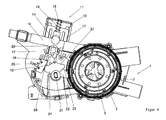
- the rotary valve 7 of the water diverter 6 and the cam disk 22 cooperating with the valve 11 are configured in their relative position with respect to one another such that an opening of the valve 11 only occurs simultaneous closure of the first discharge ports 4,5 and 30 takes place, as in FIG. 1 shown.
- FIG. 3 shows the middle position of the water diverter drive 8, according to which the valve 11 is closed.
- FIG. 4 shows an end position of the water diverter 8, which is still closed according to the valve 11 at the same time open discharge nozzle 4, 5 and 30.
- an alternating operation of the discharge nozzles 4, 5 and 30 takes place, wherein due to the cam plate 22 provided by the cam 23, an intermediate opening of the valve 11 is not performed.
- An opening of the valve 11 takes place only in the opposite end position of the water diverter 8 FIG. 1 instead, in which case the first discharge ports 4, 5 and 30 are all closed.
- FIGS. 5a and 5b An alternative embodiment of the circulation pump 1 is in FIGS. 5a and 5b shown.
- a hose 10 which branches further in the following and has two arms 28 and 29, is connected to a first pressure port 4. Due to this two arm embodiment of the hose 10 is required in contrast to vorerläuterten construction no physically trained additional pressure port 9. Functionally, this is formed by the first discharge port 4 in combination with the lockable designed arm 28 of the hose 10.
- the control of the valve device 12 corresponds to that of the vorerläuterten FIGS. 1 to 4 , FIG. 5a represents a valve setting in which arm 29 is shut off and arm 28 is opened while in FIG. 5b a valve position is shown in the inverted arm 29 is opened and arm 28 is shut off.
Landscapes
- Engineering & Computer Science (AREA)
- Water Supply & Treatment (AREA)
- Mechanical Engineering (AREA)
- General Engineering & Computer Science (AREA)
- Washing And Drying Of Tableware (AREA)
- Structures Of Non-Positive Displacement Pumps (AREA)
Applications Claiming Priority (1)
| Application Number | Priority Date | Filing Date | Title |
|---|---|---|---|
| DE102011056588A DE102011056588B3 (de) | 2011-12-19 | 2011-12-19 | Umwälzpumpe für einen Geschirrspülautomaten |
Publications (2)
| Publication Number | Publication Date |
|---|---|
| EP2606809A2 true EP2606809A2 (fr) | 2013-06-26 |
| EP2606809A3 EP2606809A3 (fr) | 2017-11-08 |
Family
ID=47019819
Family Applications (1)
| Application Number | Title | Priority Date | Filing Date |
|---|---|---|---|
| EP12401240.2A Withdrawn EP2606809A3 (fr) | 2011-12-19 | 2012-12-03 | Pompe de recirculation pour un automate de lave-vaisselle |
Country Status (2)
| Country | Link |
|---|---|
| EP (1) | EP2606809A3 (fr) |
| DE (1) | DE102011056588B3 (fr) |
Families Citing this family (1)
| Publication number | Priority date | Publication date | Assignee | Title |
|---|---|---|---|---|
| DE102014106912A1 (de) * | 2014-05-16 | 2015-11-19 | Miele & Cie. Kg | Verfahren zum Betrieb einer Wasserweiche und Wasserweiche zur Durchführung dieses Verfahrens |
Citations (3)
| Publication number | Priority date | Publication date | Assignee | Title |
|---|---|---|---|---|
| DE3904359A1 (de) | 1988-05-13 | 1990-08-16 | Licentia Gmbh | Geschirrspuelmaschine mit einer elektromechanischen umsteuervorrichtung |
| DE10133130A1 (de) | 2001-07-07 | 2003-01-16 | Miele & Cie | Umwälzpumpe mit/ohne Heizungseinrichtung |
| US7270132B2 (en) | 2000-02-14 | 2007-09-18 | Matsushita Electric Industrial Co., Ltd. | Washer |
Family Cites Families (1)
| Publication number | Priority date | Publication date | Assignee | Title |
|---|---|---|---|---|
| KR101526987B1 (ko) * | 2008-08-21 | 2015-06-11 | 엘지전자 주식회사 | 식기 세척기 및 그 제어방법 |
-
2011
- 2011-12-19 DE DE102011056588A patent/DE102011056588B3/de not_active Expired - Fee Related
-
2012
- 2012-12-03 EP EP12401240.2A patent/EP2606809A3/fr not_active Withdrawn
Patent Citations (3)
| Publication number | Priority date | Publication date | Assignee | Title |
|---|---|---|---|---|
| DE3904359A1 (de) | 1988-05-13 | 1990-08-16 | Licentia Gmbh | Geschirrspuelmaschine mit einer elektromechanischen umsteuervorrichtung |
| US7270132B2 (en) | 2000-02-14 | 2007-09-18 | Matsushita Electric Industrial Co., Ltd. | Washer |
| DE10133130A1 (de) | 2001-07-07 | 2003-01-16 | Miele & Cie | Umwälzpumpe mit/ohne Heizungseinrichtung |
Also Published As
| Publication number | Publication date |
|---|---|
| DE102011056588B3 (de) | 2012-11-08 |
| EP2606809A3 (fr) | 2017-11-08 |
Similar Documents
| Publication | Publication Date | Title |
|---|---|---|
| EP3285632B1 (fr) | Bras gicleur et lave-vaisselle | |
| EP2601878B1 (fr) | Lave-vaisselle avec inversion automatique du sens de rotation du bras pulvérisateur | |
| EP2982288B1 (fr) | Lave-vaisselle, notamment lave-vaisselle menager | |
| DE202017104994U1 (de) | Spray-Mopp | |
| EP2601877B1 (fr) | Lave-vaisselle avec inversion automatique du sens de rotation du bras pulvérisateur | |
| EP2510865B1 (fr) | Lave-vaisselle automatique | |
| EP1046369B1 (fr) | Soupape à deux voies pour un appareil ménager de conduisant du liquide | |
| DE102004018878B4 (de) | Geschirrspülmaschine mit einem Spülbehälter in dem wenigstens ein Sprüharm angeordnet ist | |
| DE8816597U1 (de) | Umschalteinrichtung in der Umwälzleitung einer Wasch- oder Geschirrspülmaschine | |
| DE1908580A1 (de) | Steuervorrichtung fuer Klappenventile | |
| DE19926962B4 (de) | Geschirrspülmaschine mit höhenverstellbarem Korb | |
| DE19947323A1 (de) | Haushalt-Geschirrspülmaschine | |
| DE10024014C2 (de) | Dosiervorrichtung für flüssiges Spülmittel | |
| EP3733041B1 (fr) | Appareil de dosage | |
| DE3602663A1 (de) | Vorrichtung zur ausgabe von reinigungsmitteln und klarspuelmitteln in geschirrspuelmaschinen | |
| DE102009002667B4 (de) | Geschirrspülmaschine und Umwälzpumpe mit Wasserweiche | |
| DE102011056588B3 (de) | Umwälzpumpe für einen Geschirrspülautomaten | |
| DE10135555B4 (de) | Umstellvorrichtung für eine Sanitäreinrichtung mit mindestens zwei Wasserverbrauchern | |
| EP1926418B1 (fr) | Lave-vaisselle electromenager | |
| DE102011007685A1 (de) | Geschirrspülmaschine | |
| DE10246407A1 (de) | Ventilaggregat, ggf. Umlenk-Ventilaggregat, insbesondere für eine Geschirrspül- und Geschirrtrockner-Maschine | |
| DE19626823A1 (de) | Elektrisches Durchflußsperrventil | |
| EP4478931B1 (fr) | Unité de dosage pour dispositif de nettoyage et dispositif de nettoyage | |
| EP4491088B1 (fr) | Lave-vaisselle | |
| DE2335195A1 (de) | Sicherheitsvorrichtung zur ueberwachung des wasserkreislaufes bei waschmaschinen, geschirrspuelmaschinen u. dgl |
Legal Events
| Date | Code | Title | Description |
|---|---|---|---|
| AK | Designated contracting states |
Kind code of ref document: A2 Designated state(s): AL AT BE BG CH CY CZ DE DK EE ES FI FR GB GR HR HU IE IS IT LI LT LU LV MC MK MT NL NO PL PT RO RS SE SI SK SM TR |
|
| AX | Request for extension of the european patent |
Extension state: BA ME |
|
| PUAI | Public reference made under article 153(3) epc to a published international application that has entered the european phase |
Free format text: ORIGINAL CODE: 0009012 |
|
| PUAL | Search report despatched |
Free format text: ORIGINAL CODE: 0009013 |
|
| AK | Designated contracting states |
Kind code of ref document: A3 Designated state(s): AL AT BE BG CH CY CZ DE DK EE ES FI FR GB GR HR HU IE IS IT LI LT LU LV MC MK MT NL NO PL PT RO RS SE SI SK SM TR |
|
| RIC1 | Information provided on ipc code assigned before grant |
Ipc: A47L 15/42 20060101AFI20171002BHEP Ipc: F04D 15/00 20060101ALI20171002BHEP |
|
| STAA | Information on the status of an ep patent application or granted ep patent |
Free format text: STATUS: THE APPLICATION IS DEEMED TO BE WITHDRAWN |
|
| 18D | Application deemed to be withdrawn |
Effective date: 20180509 |