EP2606841B1 - Dispositif polyaxial d'ancrage osseux - Google Patents
Dispositif polyaxial d'ancrage osseux Download PDFInfo
- Publication number
- EP2606841B1 EP2606841B1 EP11195714.8A EP11195714A EP2606841B1 EP 2606841 B1 EP2606841 B1 EP 2606841B1 EP 11195714 A EP11195714 A EP 11195714A EP 2606841 B1 EP2606841 B1 EP 2606841B1
- Authority
- EP
- European Patent Office
- Prior art keywords
- head
- lugs
- bone anchoring
- anchoring device
- polyaxial bone
- Prior art date
- Legal status (The legal status is an assumption and is not a legal conclusion. Google has not performed a legal analysis and makes no representation as to the accuracy of the status listed.)
- Active
Links
Images


Classifications
-
- A—HUMAN NECESSITIES
- A61—MEDICAL OR VETERINARY SCIENCE; HYGIENE
- A61B—DIAGNOSIS; SURGERY; IDENTIFICATION
- A61B17/00—Surgical instruments, devices or methods
- A61B17/56—Surgical instruments or methods for treatment of bones or joints; Devices specially adapted therefor
- A61B17/58—Surgical instruments or methods for treatment of bones or joints; Devices specially adapted therefor for osteosynthesis, e.g. bone plates, screws or setting implements
- A61B17/68—Internal fixation devices, including fasteners and spinal fixators, even if a part thereof projects from the skin
- A61B17/70—Spinal positioners or stabilisers, e.g. stabilisers comprising fluid filler in an implant
- A61B17/7001—Screws or hooks combined with longitudinal elements which do not contact vertebrae
- A61B17/7035—Screws or hooks, wherein a rod-clamping part and a bone-anchoring part can pivot relative to each other
- A61B17/7037—Screws or hooks, wherein a rod-clamping part and a bone-anchoring part can pivot relative to each other wherein pivoting is blocked when the rod is clamped
-
- A—HUMAN NECESSITIES
- A61—MEDICAL OR VETERINARY SCIENCE; HYGIENE
- A61B—DIAGNOSIS; SURGERY; IDENTIFICATION
- A61B17/00—Surgical instruments, devices or methods
- A61B17/56—Surgical instruments or methods for treatment of bones or joints; Devices specially adapted therefor
- A61B17/58—Surgical instruments or methods for treatment of bones or joints; Devices specially adapted therefor for osteosynthesis, e.g. bone plates, screws or setting implements
- A61B17/68—Internal fixation devices, including fasteners and spinal fixators, even if a part thereof projects from the skin
- A61B17/70—Spinal positioners or stabilisers, e.g. stabilisers comprising fluid filler in an implant
- A61B17/7001—Screws or hooks combined with longitudinal elements which do not contact vertebrae
- A61B17/7032—Screws or hooks with U-shaped head or back through which longitudinal rods pass
-
- A—HUMAN NECESSITIES
- A61—MEDICAL OR VETERINARY SCIENCE; HYGIENE
- A61B—DIAGNOSIS; SURGERY; IDENTIFICATION
- A61B17/00—Surgical instruments, devices or methods
- A61B17/56—Surgical instruments or methods for treatment of bones or joints; Devices specially adapted therefor
- A61B17/58—Surgical instruments or methods for treatment of bones or joints; Devices specially adapted therefor for osteosynthesis, e.g. bone plates, screws or setting implements
- A61B17/68—Internal fixation devices, including fasteners and spinal fixators, even if a part thereof projects from the skin
- A61B17/70—Spinal positioners or stabilisers, e.g. stabilisers comprising fluid filler in an implant
- A61B17/7001—Screws or hooks combined with longitudinal elements which do not contact vertebrae
- A61B17/7035—Screws or hooks, wherein a rod-clamping part and a bone-anchoring part can pivot relative to each other
-
- A—HUMAN NECESSITIES
- A61—MEDICAL OR VETERINARY SCIENCE; HYGIENE
- A61B—DIAGNOSIS; SURGERY; IDENTIFICATION
- A61B17/00—Surgical instruments, devices or methods
- A61B17/56—Surgical instruments or methods for treatment of bones or joints; Devices specially adapted therefor
- A61B17/58—Surgical instruments or methods for treatment of bones or joints; Devices specially adapted therefor for osteosynthesis, e.g. bone plates, screws or setting implements
- A61B17/68—Internal fixation devices, including fasteners and spinal fixators, even if a part thereof projects from the skin
- A61B17/84—Fasteners therefor or fasteners being internal fixation devices
- A61B17/86—Pins or screws or threaded wires; nuts therefor
-
- A—HUMAN NECESSITIES
- A61—MEDICAL OR VETERINARY SCIENCE; HYGIENE
- A61B—DIAGNOSIS; SURGERY; IDENTIFICATION
- A61B90/00—Instruments, implements or accessories specially adapted for surgery or diagnosis and not covered by any of the groups A61B1/00 - A61B50/00, e.g. for luxation treatment or for protecting wound edges
- A61B90/03—Automatic limiting or abutting means, e.g. for safety
- A61B2090/037—Automatic limiting or abutting means, e.g. for safety with a frangible part, e.g. by reduced diameter
Definitions
- the invention relates to a polyaxial bone anchoring device for anchoring a stabilization rod in bones or in vertebrae.
- the bone anchoring device includes an anchoring element, a receiving part for receiving a head of the bone anchoring element and for receiving a stabilization rod to be connected to the anchoring element.
- the anchoring element is pivotably held in a seat in the receiving part and can be fixed at an angle by exerting pressure onto the head via a pressure element which is arranged in the receiving part.
- the anchoring element has a head with a spherical outer surface portion including a largest outer diameter and the pressure element comprises a head contacting surface portion including at least two circumferentially distinct lugs extending along a region including the largest outer diameter of the head when the pressure element is placed onto the head.
- the pressure element has an undersize in the region of the lugs with respect to the head such that the head is clamped by the friction between the head and the lugs and allows the anchoring element to be maintained in a desired angular position before
- US 2004/0267264 A1 describes a polyaxial fixation device wherein the polyaxial bone screw includes an engagement member that is adapted to provide sufficient friction between the spherical head and the receiver member to enable the shank to be maintained in a desired angular orientation before locking the spherical head within the receiver member.
- the engagement member is realized, for example, by an open snap ring around the head or by spring members provided at the compression cap to frictionally engage the spherical head or by a slot provided in the compression cap.
- Document US 6,355,040 B1 discloses a locking mechanism, wherein a head of a screw member is locked by providing a screw retaining insert to a rod retaining ring, the insert having: a recess allowing to collapse the insert onto the head, a partially spherical seat and a number of outwardly tapering tabs.
- the tabs may each be received in axially extending slots of the rod retaining ring. Locking of the screw member occurs by wedging inwardly tapered inner walls of the tabs against the screw head.
- the bone anchoring device With the bone anchoring device a slight clamping of the head in a desired angular position with respect to the receiving part without locking the head can be achieved. This allows to maintain the receiving part in an adjustable angular position. In this condition, the pressure elements exerts a preload onto the head wherein the head is not locked but prevented from freely pivoting. When the head is temporarily clamped, the alignment of the receiving part with respect to the rod and the insertion of the rod is facilitated, in particular in a situation in which a multitude of bone anchors have to be connected to the rod. When the rod is already inserted into the receiving part, adjustments of the rod are still possible without completely loosening the head.
- the amount of preload exerted onto the head by the pressure element can be exactly predefined by dimensioning the size of the pressure element with respect to the head in view of the desired friction force between the pressure element and the head.
- the bone anchoring device is simple to manufacture and uncritical in view of tolerances of the head, the receiving part and the pressure element with respect to each other.
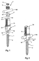
- the polyaxial bone anchoring device includes a bone anchoring element 1 in the form of a screw member having a threaded shank 2 and a head 3.
- the head 3 is shaped as a spherical segment that has a size including the equator or largest diameter E of the sphere. On its free end the head 3 has a recess 4 for engagement with a tool.
- the bone anchoring device further includes a receiving part 5 for connecting the screw member 1 to a rod 100.
- a pressure element 6 is arranged in the receiving part on top of the head 3.
- a locking device 7 for securing the rod 100 in the receiving part and for exerting pressure onto the head a locking device 7 in the form of an outer locking element 8 which cooperates with the receiving part 5 and an inner locking element 9 cooperating with the outer locking element 8 is provided.
- the receiving part 5 is substantially cylindrical and has a top end 5a, a bottom end 5b and a bore 51 extending from the top end 5a towards the bottom end 5b, the bore having a bore axis C.
- a seat portion 52 is provided for accommodating the head 3.
- the seat portion 52 is spherically-shaped with a radius corresponding substantially to the radius of the head 3 so that the head 3 is supported by the seat portion and allows the head 3 to pivot in the seat portion 52 similar to a ball and socket joint.
- the seat portion 52 further is in communication with the bore 51 and has an opening 52b through which the shank 2 of the bone anchoring element can extend.
- An inner diameter of the seat portion 52 at the transition to the bore 51 is greater than the outer diameter of the head and smaller than the inner diameter of the bore 51 such that an edge portion 52a is formed between the bore 51 and the seat portion 52.
- An internal thread 54 is provided at the receiving part adjacent the top end 5a for cooperating with the outer locking element 8 of the locking device 7.
- the receiving part 5 serves as a long head receiving part that has extended legs and comprises at a distance from the first end 5a a predetermined breaking point 5c that permits to break off the portion between the first end 5a and the predetermined breaking point 5c.
- a long head receiving part may be used, for example, for minimally invasive surgery.
- the receiving part 5 may also be designed without the long head, in such a case the first end 5a being located approximately at the predetermined breaking point 5c.
- an inclined lower surface 5d is formed, for example by cutting away a portion of the receiving part, to permit the anchoring element 1 to pivot at a larger angle to one side.
- the receiving part may be designed with a symmetrical lower end that permits symmetric angulation in all directions.
- the recesses 55 are substantially spherical-segment shaped with a radius considerably smaller than the radius of the seat portion 52.
- the recesses 55 are formed in the seat portion, that are arranged in a circumferential direction near both ends of the U-shaped recess 53 and at both sides therefrom seen in the direction of the rod axis.
- the recesses 55 locally enlarge the diameter of the seat portion and serve for providing an accommodation space for a portion of the pressure element described below.
- the pressure element 6 is formed in one piece. It is of substantially cylindrical construction and has an outer diameter which allows it to move in the axial direction in the bore 51 of the receiving part 5.
- the pressure element 6 has a top end 6a and a bottom end 6b.
- a substantially U-shaped recess 61 is provided which is configured to receive the rod 100 therein.
- the depth of the recess 61 is greater than the diameter of the rod 100 such that the free legs formed by the recess extend above the surface of the rod 100 when the rod is inserted.
- a spherical recess 62 is provided for receiving the head 3 therein.
- the radius of the spherical recess 62 is slightly larger than the radius of the head 3 so that the head 3 fits easily into the recess 62.
- At the bottom end 6b there are four cut-outs spaced substantially equidistantly in a circumferential direction whereby four lugs 63 are provided.
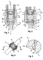
- the lugs 63 have an approximate V-shape seen in a side view, for example in Fig. 11a ), wherein the free end is flat or rounded.
- the outer contour of the lugs is not restricted to the shape shown in the embodiment.
- the lugs can be rectangular or U-shaped or otherwise shaped.
- the lugs 63 are arranged to the left side and the right side from the U-shaped recess 61 near both ends of the recess 61 corresponding to the locations of the recesses 55 in the receiving part 5.
- the length of the lugs 63 and the depth of the spherical recess 62 is such that the lugs 63 extend beyond the area with the largest outer diameter E of the spherical head 3 when the pressure element is mounted onto the head 3.
- the lugs 63 each have a first section 63a adjacent the spherical recess 62 and a second section 63b extending from the first section to the free end of the lug.
- the inner diameter D 1 of the first spherical section 63a is the same or is greater than the outer diameter of the spherical outer surface portion of the head 3 that comes into contact therewith.
- the inner diameter D 2 of the second spherical portion 63b is slightly smaller than the largest outer diameter E of the spherical surface portion of the head, for example it is approximately 1% to 2% smaller, so that the pressure element 6 has a slight undersize with respect to the head in the region of the second spherical portion 63b of the lugs 63.
- the undersize is present before the pressure element 6 is placed onto the head (3). It may depend on the actual dimensions and also on the material used.
- the pressure element 6 When the pressure element 6 is placed onto the head 3, the head 3 has to pass to the second spherical portions 63b to move into the spherical recess 62, thereby slightly expanding the second spherical portions 63b.
- the pressure element 6 is configured to hold the head by frictional forces exerted by the lugs 63 onto the head.
- the strength of the frictional forces can be adjusted by designing the size of the lugs, in particular the second spherical portion 63b, in an appropriate manner.
- the pressure element 6 has a coaxial bore 64 for allowing access to the screw head 3 with a tool.
- All parts of the bone anchoring device are made of a body-compatible material, such as a body-compatible metal, for example titanium, body-compatible metal alloys, such as, for example Nitinol or from a body-compatible plastic material, such as, for example, polyetheretherketone (PEEK) or of combinations of these materials.
- a body-compatible material such as a body-compatible metal, for example titanium, body-compatible metal alloys, such as, for example Nitinol or from a body-compatible plastic material, such as, for example, polyetheretherketone (PEEK) or of combinations of these materials.
- PEEK polyetheretherketone
- the bone anchoring device is used in a pre-assembled condition.
- the pre-assembled condition the head 3 of the bone anchoring element 1 is held in the seat 52 such that the head can pivot within the seat 52 and the shank extends through the lower opening 52b.
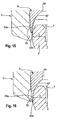
- the pressure element is placed on to the head 3 as shown in Figs. 15 and 16 .
- the pressure element 6 is aligned with the receiving part 5 such that the U-shaped recesses 53 and 61 are aligned.
- the lugs 63 are at the circumferential locations of the recesses 55 in the seat portion 52.
- the pressure element 6 is then shifted towards the bottom end 5b of the receiving part such that the second spherical portion 63b of the lugs 63 is pressed over the spherical surface portion including the largest diameter E of the head 3.
- the lugs are slightly spread outward until the head 3 fits into the spherical recess 62 and the first spherical surface portion 63a of the lugs.
- the recesses 55 provide a space for the spreading of the lugs 63.
- the lugs do not engage the wall of the recesses so that a jamming of the pressure element within the receiving part 5 does not occur.
- the head 3 contacts the spherical recess 62 and the lugs 63 over a certain contact area.
- the lugs exert a preload onto the head so that the head is clamped by the frictional forces exerted by the lugs 63.
- the pressure element may be preliminarily held in this position by crimping it through crimp bores 70, shown in Fig. 3 .
- At least two bone anchoring devices are anchored into bone parts or vertebrae. Then the receiving parts are aligned to have the correct orientation for the insertion of the rod 100. Because the head is temporarily clamped for pivoting the receiving parts, it is necessary to apply a force, for example manually, to overcome the clamping force until each receiving part has the correct orientation.
- the rod connecting the bone anchoring devices is inserted and the locking device 7 is tightened. With the outer locking element 8 that exerts pressure only onto the pressure element 6 at the top end 6a, the angular position of the head 3 is locked. With the inner locking element 7 that exerts pressure only onto the rod 100, the rod is fixed.
- the number and location of the lugs may vary.
- Other means for preliminarily fixing the pressure element within the receiving part are conceivable.
- the receiving part may be held by the action of engagement portions of the receiving part and the pressure element that prevents escaping of the pressure element through the top end 5a of the receiving part 5.
- anchoring element all kinds of anchoring elements can be used and combined with a receiving part.
- These anchoring element are e.g. screws of different lengths, with different diameters, cannulated screws, screws with different thread forms, nails, etc.
- the head and the shaft can be separate parts that are connectable to each other.
- receiving parts can be used in particular such with different locking devices.
- a one part locking device such as an inner screw which locks the rod and the head simultaneously can be used.
- outer nuts, outer caps, bayonet locking devices or others are also possible.
- the recesses 55 may have another shape, for example a rectangular or a U-shape
- the receiving part is configured to allow the introduction of the screw element from the bottom end.
Landscapes
- Health & Medical Sciences (AREA)
- Orthopedic Medicine & Surgery (AREA)
- Life Sciences & Earth Sciences (AREA)
- Surgery (AREA)
- Neurology (AREA)
- Heart & Thoracic Surgery (AREA)
- Engineering & Computer Science (AREA)
- Biomedical Technology (AREA)
- Nuclear Medicine, Radiotherapy & Molecular Imaging (AREA)
- Medical Informatics (AREA)
- Molecular Biology (AREA)
- Animal Behavior & Ethology (AREA)
- General Health & Medical Sciences (AREA)
- Public Health (AREA)
- Veterinary Medicine (AREA)
- Surgical Instruments (AREA)
Claims (13)
- Dispositif polyaxial d'ancrage osseux, comprenant :un élément d'ancrage (1) comportant une tige (2) pour l'ancrage dans l'os et une tête (3), la tête comportant une partie de surface extérieure sphérique qui comprend un plus grand diamètre extérieur (E) ;une pièce réceptrice (5) comportant une extrémité supérieure (5a) et une extrémité inférieure (5b), un profil en U (12) pour y recevoir une tige, un alésage (51) s'étendant depuis l'extrémité supérieure (5a) en direction de l'extrémité inférieure (5b), l'alésage comportant un axe (C) d'alésage et une partie de siège (52) pour recevoir la tête à l'extrémité inférieure, dans lequel la partie de siège (52) est sphérique ;un élément de pression (6) disposé à l'intérieur de l'alésage au-dessus de la tête, l'élément de pression (6) comportant une partie de surface (62, 63) de contact avec la tête qui est en contact avec la partie de surface extérieure sphérique de la tête (3), dans lequel la partie de surface de contact avec la tête comprend au moins deux oreilles (63) circonférentiellement distinctes qui s'étendent le long d'une zone de la tête qui comprend le plus grand diamètre extérieur (E) dans une direction axiale ;dans lequel la tête (3) peut pivoter par rapport à la pièce réceptrice (5) et on peut la fixer sous un angle donné en exerçant sur elle une pression par l'intermédiaire de l'élément de pression (6), et caractérisé en ce que l'élément de pression (6) présente, avant d'être placé sur la tête (3), une cote inférieure par rapport à la tête (3) seulement dans la zone des oreilles (63), qui comprennent un secteur sphérique (63b) ayant un diamètre sphérique intérieur (D2) qui est inférieur au plus grand diamètre (E) de la tête et dans lequel au moins le secteur sphérique (63b) s'étend sur la zone de plus grand diamètre (E) de la tête (3), de telle sorte que, quand l'élément de pression est placé sur la tête, la tête est abloquée par le frottement entre la partie de surface extérieure sphérique et les oreilles et dans lequel les oreilles s'étendent au moins en partie dans un espace de logement (55) ménagé dans la pièce réceptrice.
- Dispositif polyaxial d'ancrage osseux selon la revendication 1, dans lequel l'espace de logement est constitué par une pluralité d'évidements (55) dans la partie de siège (52).
- Dispositif polyaxial d'ancrage osseux selon la revendication 1 ou 2, dans lequel les oreilles (63) présentent chacune un premier secteur sphérique (63a) ayant un diamètre sphérique intérieur (D1) qui est égal ou légèrement supérieur au plus grand diamètre (E) de la tête et également le second secteur sphérique (63b) ayant un diamètre sphérique intérieur (D2) qui est inférieur au plus grand diamètre (E) de la tête.
- Dispositif polyaxial d'ancrage osseux selon l'une quelconque des revendications 1 à 3, dans lequel l'élément de pression (6) est sensiblement cylindrique avec une extrémité supérieure (6a) et une extrémité inférieure (6b) et dans lequel il comporte une concavité sphérique (62) à son extrémité inférieure en face de la tête.
- Dispositif polyaxial d'ancrage osseux selon l'une quelconque des revendications 1 à 4, dans lequel la partie de surface (62) de contact avec la tête excepté les oreilles (63) a un diamètre qui est égal ou légèrement supérieur au diamètre de la tête (3).
- Dispositif polyaxial d'ancrage osseux selon l'une quelconque des revendications 1 à 5, dans lequel la profondeur de l'espace de logement (55), mesurée à partir de l'axe de l'alésage, est supérieure à un rayon extérieur des oreilles (63).
- Dispositif polyaxial d'ancrage osseux selon l'une quelconque des revendications 1 à 6, dans lequel les oreilles (63) ne sont plus en contact avec la paroi intérieure de l'espace de logement (55) quand l'élément de pression est placé sur la tête (3).
- Dispositif polyaxial d'ancrage osseux selon l'une quelconque des revendications 1 à 7, dans lequel on trouve au moins deux oreilles (63) abloquant la tête depuis des côtés opposés, de préférence une pluralité d'oreilles qui sont équidistantes le long de la circonférence.
- Dispositif polyaxial d'ancrage osseux selon l'une quelconque des revendications 2 à 8, dans lequel les évidements (55) ont une forme sphérique.
- Dispositif polyaxial d'ancrage osseux selon l'une quelconque des revendications 2 à 9, dans lequel le nombre d'évidements (55) correspond au nombre d'oreilles (63).
- Dispositif polyaxial d'ancrage osseux selon l'une quelconque des revendications 1 à 10, dans lequel les oreilles (63) ont un contour sensiblement en forme de V se rétrécissant vers l'extrémité libre.
- Dispositif polyaxial d'ancrage osseux selon l'une quelconque des revendications 2 à 11, dans lequel la pièce réceptrice (5) comporte un profil en U (53) de réception de tige et l'élément de pression (6) comporte un profil en U (61) de réception de tige et dans lequel les oreilles (63) sont disposées aux emplacements des évidements (55) quand les profils en U de réception de tige de la pièce réceptrice et de l'élément de pression sont alignés.
- Dispositif polyaxial d'ancrage osseux selon l'une quelconque des revendications 1 à 13, dans lequel on fait appel à un dispositif de verrouillage (7) qui coopère avec la pièce réceptrice (5) pour verrouiller la tête (3) dans le siège (52) et immobiliser la tige (100) dans le profil en U (12).
Priority Applications (7)
| Application Number | Priority Date | Filing Date | Title |
|---|---|---|---|
| EP11195714.8A EP2606841B1 (fr) | 2011-12-23 | 2011-12-23 | Dispositif polyaxial d'ancrage osseux |
| ES11195714T ES2570782T3 (es) | 2011-12-23 | 2011-12-23 | Dispositivo de anclaje de hueso poliaxial |
| JP2012276785A JP6076069B2 (ja) | 2011-12-23 | 2012-12-19 | 多軸骨固定装置 |
| US13/720,775 US9445847B2 (en) | 2011-12-23 | 2012-12-19 | Polyaxial bone anchoring device |
| CN201210553257.0A CN103169532B (zh) | 2011-12-23 | 2012-12-19 | 多轴骨锚固装置 |
| KR1020120150883A KR20130073848A (ko) | 2011-12-23 | 2012-12-21 | 다축 뼈 고정 장치 |
| US15/246,420 US9924974B2 (en) | 2011-12-23 | 2016-08-24 | Polyaxial bone anchoring device |
Applications Claiming Priority (1)
| Application Number | Priority Date | Filing Date | Title |
|---|---|---|---|
| EP11195714.8A EP2606841B1 (fr) | 2011-12-23 | 2011-12-23 | Dispositif polyaxial d'ancrage osseux |
Publications (2)
| Publication Number | Publication Date |
|---|---|
| EP2606841A1 EP2606841A1 (fr) | 2013-06-26 |
| EP2606841B1 true EP2606841B1 (fr) | 2016-03-09 |
Family
ID=45491312
Family Applications (1)
| Application Number | Title | Priority Date | Filing Date |
|---|---|---|---|
| EP11195714.8A Active EP2606841B1 (fr) | 2011-12-23 | 2011-12-23 | Dispositif polyaxial d'ancrage osseux |
Country Status (6)
| Country | Link |
|---|---|
| US (2) | US9445847B2 (fr) |
| EP (1) | EP2606841B1 (fr) |
| JP (1) | JP6076069B2 (fr) |
| KR (1) | KR20130073848A (fr) |
| CN (1) | CN103169532B (fr) |
| ES (1) | ES2570782T3 (fr) |
Families Citing this family (40)
| Publication number | Priority date | Publication date | Assignee | Title |
|---|---|---|---|---|
| US7833250B2 (en) | 2004-11-10 | 2010-11-16 | Jackson Roger P | Polyaxial bone screw with helically wound capture connection |
| US8377100B2 (en) | 2000-12-08 | 2013-02-19 | Roger P. Jackson | Closure for open-headed medical implant |
| US8353932B2 (en) | 2005-09-30 | 2013-01-15 | Jackson Roger P | Polyaxial bone anchor assembly with one-piece closure, pressure insert and plastic elongate member |
| US11224464B2 (en) | 2002-05-09 | 2022-01-18 | Roger P. Jackson | Threaded closure with inwardly-facing tool engaging concave radiused structures and axial through-aperture |
| US7776067B2 (en) | 2005-05-27 | 2010-08-17 | Jackson Roger P | Polyaxial bone screw with shank articulation pressure insert and method |
| US9980753B2 (en) | 2009-06-15 | 2018-05-29 | Roger P Jackson | pivotal anchor with snap-in-place insert having rotation blocking extensions |
| US8444681B2 (en) | 2009-06-15 | 2013-05-21 | Roger P. Jackson | Polyaxial bone anchor with pop-on shank, friction fit retainer and winged insert |
| US8979904B2 (en) | 2007-05-01 | 2015-03-17 | Roger P Jackson | Connecting member with tensioned cord, low profile rigid sleeve and spacer with torsion control |
| CA2739997C (fr) | 2008-08-01 | 2013-08-13 | Roger P. Jackson | Element longitudinal de liaison avec cordons tendus gaines |
| CN103826560A (zh) | 2009-06-15 | 2014-05-28 | 罗杰.P.杰克逊 | 具有套接杆和带摩擦配合压缩套爪的带翼插件的多轴骨锚 |
| US12383311B2 (en) | 2010-05-14 | 2025-08-12 | Roger P. Jackson | Pivotal bone anchor assembly and method for use thereof |
| US9345519B1 (en) * | 2010-07-02 | 2016-05-24 | Presidio Surgical, Inc. | Pedicle screw |
| EP2659845A1 (fr) | 2010-12-27 | 2013-11-06 | Biedermann Technologies GmbH & Co. KG | Dispositif d'ancrage d'os polyaxial |
| US8337530B2 (en) * | 2011-03-09 | 2012-12-25 | Zimmer Spine, Inc. | Polyaxial pedicle screw with increased angulation |
| RU2013158111A (ru) | 2011-06-15 | 2015-07-20 | Смит Энд Нефью, Инк. | Имплантат с переменным углом фиксации |
| US9993269B2 (en) * | 2011-07-15 | 2018-06-12 | Globus Medical, Inc. | Orthopedic fixation devices and methods of installation thereof |
| EP2606841B1 (fr) * | 2011-12-23 | 2016-03-09 | Biedermann Technologies GmbH & Co. KG | Dispositif polyaxial d'ancrage osseux |
| US8911479B2 (en) | 2012-01-10 | 2014-12-16 | Roger P. Jackson | Multi-start closures for open implants |
| US8911478B2 (en) | 2012-11-21 | 2014-12-16 | Roger P. Jackson | Splay control closure for open bone anchor |
| US10058354B2 (en) * | 2013-01-28 | 2018-08-28 | Roger P. Jackson | Pivotal bone anchor assembly with frictional shank head seating surfaces |
| US20150073488A1 (en) * | 2013-09-09 | 2015-03-12 | James A. Rinner | Spinal stabilization system |
| US9717533B2 (en) | 2013-12-12 | 2017-08-01 | Roger P. Jackson | Bone anchor closure pivot-splay control flange form guide and advancement structure |
| EP3099257A4 (fr) * | 2014-01-29 | 2018-02-28 | Spinal USA, Inc. | Dispositifs, systèmes et procédés mini-invasifs de traitement de la colonne vertébrale |
| US11219471B2 (en) | 2014-10-21 | 2022-01-11 | Roger P. Jackson | Pivotal bone anchor receiver having an insert with post-placement tool deployment |
| US10543021B2 (en) | 2014-10-21 | 2020-01-28 | Roger P. Jackson | Pivotal bone anchor assembly having an open ring positioner for a retainer |
| US10993750B2 (en) | 2015-09-18 | 2021-05-04 | Smith & Nephew, Inc. | Bone plate |
| EP3419537B1 (fr) | 2016-02-26 | 2021-09-01 | Medos International Sarl | Élément de fixation d'os polyaxial |
| US10779866B2 (en) | 2016-12-29 | 2020-09-22 | K2M, Inc. | Rod reducer assembly |
| WO2018186887A1 (fr) * | 2017-04-07 | 2018-10-11 | Facet-Link Inc. | Élément de fixation vertébrale et système de stabilisation |
| US11026730B2 (en) | 2017-05-10 | 2021-06-08 | Medos International Sarl | Bone anchors with drag features and related methods |
| US10610265B1 (en) | 2017-07-31 | 2020-04-07 | K2M, Inc. | Polyaxial bone screw with increased angulation |
| EP3476340B1 (fr) | 2017-10-25 | 2021-06-02 | Biedermann Technologies GmbH & Co. KG | Dispositif d'ancrage d'os polyaxial |
| IT201900005358A1 (it) * | 2019-04-08 | 2020-10-08 | Medacta Int Sa | Vite chirurgica poliassiale e dispositivo per l’impianto di detta vite chirurgica |
| US11571244B2 (en) | 2019-05-22 | 2023-02-07 | Nuvasive, Inc. | Posterior spinal fixation screws |
| EP3766443B1 (fr) | 2019-07-18 | 2023-02-15 | Biedermann Technologies GmbH & Co. KG | Dispositif d'ancrage d'os |
| EP3871624B1 (fr) | 2020-02-25 | 2023-07-19 | Biedermann Technologies GmbH & Co. KG | Dispositif d'ancrage d'os |
| EP3878386B1 (fr) * | 2020-03-12 | 2023-08-30 | Biedermann Technologies GmbH & Co. KG | Dispositif de couplage à utiliser avec un élément d'ancrage osseux et dispositif d'ancrage osseux comportant un tel dispositif |
| AU2022229772A1 (en) * | 2021-03-05 | 2023-10-19 | Medos International Sarl | Multi-feature polyaxial screw |
| US20220395298A1 (en) * | 2021-06-11 | 2022-12-15 | Anza Innovations, Inc. | Modular Bone Anchor Assembly |
| US11751915B2 (en) | 2021-07-09 | 2023-09-12 | Roger P. Jackson | Modular spinal fixation system with bottom-loaded universal shank heads |
Family Cites Families (74)
| Publication number | Priority date | Publication date | Assignee | Title |
|---|---|---|---|---|
| US6010503A (en) * | 1998-04-03 | 2000-01-04 | Spinal Innovations, Llc | Locking mechanism |
| DE10055888C1 (de) * | 2000-11-10 | 2002-04-25 | Biedermann Motech Gmbh | Knochenschraube |
| US6488681B2 (en) * | 2001-01-05 | 2002-12-03 | Stryker Spine S.A. | Pedicle screw assembly |
| FR2822053B1 (fr) | 2001-03-15 | 2003-06-20 | Stryker Spine Sa | Organe d'ancrage avec bague de securite pour systeme d'osteosynthese rachidienne |
| DE10115014A1 (de) * | 2001-03-27 | 2002-10-24 | Biedermann Motech Gmbh | Verankerungselement |
| US7087057B2 (en) * | 2003-06-27 | 2006-08-08 | Depuy Acromed, Inc. | Polyaxial bone screw |
| SE526887C2 (sv) * | 2003-10-01 | 2005-11-15 | Nobel Biocare Ab | Anordning vid implantat med invändig fattning för vridverktyg |
| EP2050407A1 (fr) * | 2003-12-30 | 2009-04-22 | DePuy Spine Sàrl | Ensembles d'ancrage d'os |
| DE102004010380A1 (de) * | 2004-03-03 | 2005-09-22 | Biedermann Motech Gmbh | Verankerungselement und Stabilisierungseinrichtung zur dynamischen Stabilisierung von Wirbeln bzw. Knochen mit einem solchen Verankerungselement |
| US8926672B2 (en) * | 2004-11-10 | 2015-01-06 | Roger P. Jackson | Splay control closure for open bone anchor |
| US8444681B2 (en) * | 2009-06-15 | 2013-05-21 | Roger P. Jackson | Polyaxial bone anchor with pop-on shank, friction fit retainer and winged insert |
| DE102005009282A1 (de) * | 2005-02-22 | 2006-08-24 | Aesculap Ag & Co. Kg | Implantatsystem und Befestigungselement für ein Implantatsystem |
| US7951172B2 (en) * | 2005-03-04 | 2011-05-31 | Depuy Spine Sarl | Constrained motion bone screw assembly |
| US8221472B2 (en) * | 2005-04-25 | 2012-07-17 | Synthes Usa, Llc | Bone anchor with locking cap and method of spinal fixation |
| ES2313182T3 (es) * | 2005-10-12 | 2009-03-01 | Biedermann Motech Gmbh | Tormillo poliaxial pivotable en un solo plano. |
| US8100946B2 (en) * | 2005-11-21 | 2012-01-24 | Synthes Usa, Llc | Polyaxial bone anchors with increased angulation |
| JP2009540872A (ja) * | 2006-03-22 | 2009-11-26 | パイオニア サージカル テクノロジー インコーポレイテッド | ロートップ骨固定システム及びその使用方法 |
| DE602006009069D1 (de) * | 2006-04-06 | 2009-10-22 | Biedermann Motech Gmbh | Abgewinkelte polyaxiale Knochenverankerungsvorrichtung |
| CN101500500B (zh) * | 2006-06-05 | 2011-05-11 | 特雷伯有限公司 | 脊椎的固定装置 |
| WO2008008511A2 (fr) * | 2006-07-14 | 2008-01-17 | Laszlo Garamszegi | Ensemble de vis pédiculaire avec siège de surface incliné |
| US7942910B2 (en) * | 2007-05-16 | 2011-05-17 | Ortho Innovations, Llc | Polyaxial bone screw |
| CN101754725B (zh) * | 2007-07-20 | 2011-12-21 | 新特斯有限责任公司 | 多轴骨固定元件 |
| US9439681B2 (en) * | 2007-07-20 | 2016-09-13 | DePuy Synthes Products, Inc. | Polyaxial bone fixation element |
| US20100160980A1 (en) * | 2007-07-26 | 2010-06-24 | Biotechni America Spine Group, Inc. | Spinal fixation assembly |
| DE102007042953B4 (de) * | 2007-08-30 | 2015-01-22 | Aesculap Ag | Orthopädisches Haltesystem |
| US8398683B2 (en) * | 2007-10-23 | 2013-03-19 | Pioneer Surgical Technology, Inc. | Rod coupling assembly and methods for bone fixation |
| GB0720762D0 (en) * | 2007-10-24 | 2007-12-05 | Depuy Spine Sorl | Assembly for orthopaedic surgery |
| US8007522B2 (en) * | 2008-02-04 | 2011-08-30 | Depuy Spine, Inc. | Methods for correction of spinal deformities |
| US8157846B2 (en) * | 2008-07-24 | 2012-04-17 | Ingenium S.A. | Locking mechanism with two-piece washer |
| US8506601B2 (en) * | 2008-10-14 | 2013-08-13 | Pioneer Surgical Technology, Inc. | Low profile dual locking fixation system and offset anchor member |
| US8382809B2 (en) * | 2008-10-17 | 2013-02-26 | Omni Surgical | Poly-axial pedicle screw implements and lock screw therefor |
| WO2010062736A1 (fr) * | 2008-11-03 | 2010-06-03 | Synthes Usa, Llc | Ensemble fixation osseuse plane |
| US8075603B2 (en) * | 2008-11-14 | 2011-12-13 | Ortho Innovations, Llc | Locking polyaxial ball and socket fastener |
| WO2010065648A1 (fr) * | 2008-12-02 | 2010-06-10 | Eminent Spine Llc | Système de fixation de vis pédiculaire et procédé d'utilisation de celui-ci |
| EP2221013B1 (fr) | 2009-02-20 | 2015-08-05 | Biedermann Technologies GmbH & Co. KG | Pièce de réception pour recevoir une tige pour coupler la tige sur un élément d'ancrage d'os et dispositif d'ancrage d'os avec une telle pièce de réception |
| US8241341B2 (en) * | 2009-03-20 | 2012-08-14 | Spinal Usa, Inc. | Pedicle screws and methods of using the same |
| JP2012523927A (ja) * | 2009-04-15 | 2012-10-11 | ジンテス ゲゼルシャフト ミット ベシュレンクテル ハフツング | 脊椎構成物のための修正コネクタ |
| JP5654584B2 (ja) * | 2009-06-17 | 2015-01-14 | ジンテス ゲゼルシャフト ミット ベシュレンクテル ハフツング | 脊柱構築用の修正コネクタ |
| ES2545206T3 (es) * | 2009-08-12 | 2015-09-09 | Biedermann Technologies Gmbh & Co. Kg | Pieza de alojamiento para alojar una varilla con el fin de acoplar la varilla a un elemento de anclaje óseo |
| US8449578B2 (en) * | 2009-11-09 | 2013-05-28 | Ebi, Llc | Multiplanar bone anchor system |
| WO2011062573A1 (fr) * | 2009-11-18 | 2011-05-26 | Synthes Usa, Llc | Système et procédé de fixation rachidienne à décalage variable |
| US8419778B2 (en) * | 2010-01-15 | 2013-04-16 | Ebi, Llc | Uniplanar bone anchor system |
| US20110196430A1 (en) | 2010-02-10 | 2011-08-11 | Walsh David A | Spinal fixation assembly with intermediate element |
| DE102010028423B4 (de) * | 2010-04-30 | 2016-04-14 | Kilian Kraus | Pedikelschraube und Vorrichtung zur Stabilisierung der Wirbelsäule |
| US9393049B2 (en) * | 2010-08-20 | 2016-07-19 | K2M, Inc. | Spinal fixation system |
| US8974501B2 (en) * | 2010-10-18 | 2015-03-10 | Alphatec Spine, Inc. | Distal loading receiver for a polyaxial bone screw and method for implantation thereof |
| EP2460484A1 (fr) * | 2010-12-01 | 2012-06-06 | FACET-LINK Inc. | Agencement de fixation de vis d'os à angle variable |
| US9044274B2 (en) * | 2010-12-01 | 2015-06-02 | Amendia, Inc. | Bone screw system |
| EP2737864B1 (fr) * | 2010-12-10 | 2017-04-12 | Biedermann Technologies GmbH & Co. KG | Pièce de réception pour recevoir une tige pour coupler la tige sur un élément d'ancrage d'os et dispositif d'ancrage d'os |
| EP2659845A1 (fr) * | 2010-12-27 | 2013-11-06 | Biedermann Technologies GmbH & Co. KG | Dispositif d'ancrage d'os polyaxial |
| US8882806B2 (en) * | 2011-04-25 | 2014-11-11 | Said ELSHIHABI | Spine stabilization system with self-cutting rod |
| US8845693B2 (en) * | 2011-04-27 | 2014-09-30 | Jeffrey Scott Smith | Tulip head apparatus |
| US20130096618A1 (en) * | 2011-10-14 | 2013-04-18 | Thibault Chandanson | Bone anchor assemblies |
| US8956361B2 (en) * | 2011-12-19 | 2015-02-17 | Amendia, Inc. | Extended tab bone screw system |
| EP2606841B1 (fr) * | 2011-12-23 | 2016-03-09 | Biedermann Technologies GmbH & Co. KG | Dispositif polyaxial d'ancrage osseux |
| EP2620112B1 (fr) * | 2012-01-30 | 2014-11-12 | Biedermann Technologies GmbH & Co. KG | Dispositif d'ancrage d'os |
| KR101199458B1 (ko) * | 2012-02-17 | 2012-11-09 | 고려대학교 산학협력단 | 척추 고정용 장치 |
| ES2563785T3 (es) * | 2012-06-01 | 2016-03-16 | Biedermann Technologies Gmbh & Co. Kg | Dispositivo de anclaje de hueso poliaxial |
| ES2606151T3 (es) * | 2012-07-27 | 2017-03-22 | Biedermann Technologies Gmbh & Co. Kg | Dispositivo de anclaje óseo poliaxial con ángulo de giro ampliado |
| US9572598B2 (en) * | 2012-08-09 | 2017-02-21 | Spine Craft, LLC | Uniplanar surgical screw assembly |
| ES2616212T3 (es) * | 2012-10-09 | 2017-06-09 | Biedermann Technologies Gmbh & Co. Kg | Instrumento de montaje de un dispositivo de anclaje óseo poliaxial |
| US8911478B2 (en) * | 2012-11-21 | 2014-12-16 | Roger P. Jackson | Splay control closure for open bone anchor |
| EP2740424B1 (fr) * | 2012-12-10 | 2015-10-14 | Biedermann Technologies GmbH & Co. KG | Élément d'ancrage approprié pour être utilisé dans un dispositif d'ancrage osseux polyaxial et dispositif d'ancrage osseux polyaxial avec un angle de pivotement élargi vers un côté |
| EP2764840B1 (fr) * | 2013-02-11 | 2017-05-03 | Biedermann Technologies GmbH & Co. KG | Ensemble de couplage d'une tige à un élément d'ancrage osseux et dispositif d'ancrage osseux avec un tel ensemble de couplage |
| US20140277153A1 (en) * | 2013-03-14 | 2014-09-18 | DePuy Synthes Products, LLC | Bone Anchor Assemblies and Methods With Improved Locking |
| US10342582B2 (en) * | 2013-03-14 | 2019-07-09 | DePuy Synthes Products, Inc. | Bone anchor assemblies and methods with improved locking |
| US9259247B2 (en) * | 2013-03-14 | 2016-02-16 | Medos International Sarl | Locking compression members for use with bone anchor assemblies and methods |
| US20140277159A1 (en) * | 2013-03-14 | 2014-09-18 | DePuy Synthes Products, LLC | Bottom-loading bone anchor assemblies |
| US20150012042A1 (en) * | 2013-07-04 | 2015-01-08 | Institute for Musculoskeletal Science and Education, Ltd. | Orthopedic implantation device |
| EP3021771A1 (fr) * | 2013-07-18 | 2016-05-25 | Ortho Innovations, LLC | Dispositif de fixation à articulation à rotule polyaxiale à chargement inférieur à bague de serrage |
| US9480501B2 (en) * | 2013-10-21 | 2016-11-01 | Blackstone Medical, Inc. | Modular pedicle screw |
| US20150134006A1 (en) * | 2013-11-08 | 2015-05-14 | Blackstone Medical, Inc. | Lockable Pedicle Fastener |
| EP2873383B1 (fr) * | 2013-11-14 | 2016-10-19 | Biedermann Technologies GmbH & Co. KG | Dispositif d'ancrage d'os polyaxial doté d'un angle de pivot élargi |
| US10039572B2 (en) * | 2014-02-17 | 2018-08-07 | FloSpine LLC | Polyaxial bone anchor incorporating a two position saddle assembly |
-
2011
- 2011-12-23 EP EP11195714.8A patent/EP2606841B1/fr active Active
- 2011-12-23 ES ES11195714T patent/ES2570782T3/es active Active
-
2012
- 2012-12-19 JP JP2012276785A patent/JP6076069B2/ja active Active
- 2012-12-19 CN CN201210553257.0A patent/CN103169532B/zh active Active
- 2012-12-19 US US13/720,775 patent/US9445847B2/en active Active
- 2012-12-21 KR KR1020120150883A patent/KR20130073848A/ko not_active Ceased
-
2016
- 2016-08-24 US US15/246,420 patent/US9924974B2/en active Active
Also Published As
| Publication number | Publication date |
|---|---|
| US9445847B2 (en) | 2016-09-20 |
| JP2013132556A (ja) | 2013-07-08 |
| EP2606841A1 (fr) | 2013-06-26 |
| US20130165977A1 (en) | 2013-06-27 |
| KR20130073848A (ko) | 2013-07-03 |
| US20170049483A1 (en) | 2017-02-23 |
| JP6076069B2 (ja) | 2017-02-08 |
| CN103169532B (zh) | 2017-04-12 |
| CN103169532A (zh) | 2013-06-26 |
| ES2570782T3 (es) | 2016-05-20 |
| US9924974B2 (en) | 2018-03-27 |
Similar Documents
| Publication | Publication Date | Title |
|---|---|---|
| EP2606841A1 (fr) | Dispositif polyaxial d'ancrage osseux | |
| US20250186090A1 (en) | Bone anchoring device | |
| EP2662038B1 (fr) | Dispositif d'ancrage d'os polyaxial | |
| EP2468198B1 (fr) | Dispositif d'ancrage d'os | |
| EP2687171B1 (fr) | Dispositif d'ancrage d'os polyaxial | |
| EP2586392B1 (fr) | Dispositif d'ancrage d'os polyaxial à angulation élevée | |
| EP2457527B1 (fr) | Dispositif d'ancrage d'os polyaxial doté d'un angle de pivot élargi | |
| EP2455028B1 (fr) | Dispositif d'ancrage d'os polyaxial | |
| EP2674123B1 (fr) | Dispositif d'ancrage d'os polyaxial | |
| EP2604204B1 (fr) | Dispositif d'ancrage d'os monoplanaire doté d'un plan d'articulation sélectionnable |
Legal Events
| Date | Code | Title | Description |
|---|---|---|---|
| AK | Designated contracting states |
Kind code of ref document: A1 Designated state(s): AL AT BE BG CH CY CZ DE DK EE ES FI FR GB GR HR HU IE IS IT LI LT LU LV MC MK MT NL NO PL PT RO RS SE SI SK SM TR |
|
| AX | Request for extension of the european patent |
Extension state: BA ME |
|
| PUAI | Public reference made under article 153(3) epc to a published international application that has entered the european phase |
Free format text: ORIGINAL CODE: 0009012 |
|
| 17P | Request for examination filed |
Effective date: 20131223 |
|
| RBV | Designated contracting states (corrected) |
Designated state(s): AL AT BE BG CH CY CZ DE DK EE ES FI FR GB GR HR HU IE IS IT LI LT LU LV MC MK MT NL NO PL PT RO RS SE SI SK SM TR |
|
| 17Q | First examination report despatched |
Effective date: 20140417 |
|
| GRAP | Despatch of communication of intention to grant a patent |
Free format text: ORIGINAL CODE: EPIDOSNIGR1 |
|
| RIC1 | Information provided on ipc code assigned before grant |
Ipc: A61B 19/00 20060101AFI20150701BHEP Ipc: A61B 17/70 20060101ALI20150701BHEP |
|
| INTG | Intention to grant announced |
Effective date: 20150720 |
|
| GRAS | Grant fee paid |
Free format text: ORIGINAL CODE: EPIDOSNIGR3 |
|
| GRAA | (expected) grant |
Free format text: ORIGINAL CODE: 0009210 |
|
| RIC1 | Information provided on ipc code assigned before grant |
Ipc: A61B 17/70 20060101AFI20160113BHEP |
|
| AK | Designated contracting states |
Kind code of ref document: B1 Designated state(s): AL AT BE BG CH CY CZ DE DK EE ES FI FR GB GR HR HU IE IS IT LI LT LU LV MC MK MT NL NO PL PT RO RS SE SI SK SM TR |
|
| REG | Reference to a national code |
Ref country code: GB Ref legal event code: FG4D |
|
| REG | Reference to a national code |
Ref country code: AT Ref legal event code: REF Ref document number: 778895 Country of ref document: AT Kind code of ref document: T Effective date: 20160315 Ref country code: CH Ref legal event code: EP Ref country code: CH Ref legal event code: NV Representative=s name: NOVAGRAAF INTERNATIONAL SA, CH |
|
| REG | Reference to a national code |
Ref country code: IE Ref legal event code: FG4D |
|
| REG | Reference to a national code |
Ref country code: DE Ref legal event code: R096 Ref document number: 602011023816 Country of ref document: DE |
|
| REG | Reference to a national code |
Ref country code: ES Ref legal event code: FG2A Ref document number: 2570782 Country of ref document: ES Kind code of ref document: T3 Effective date: 20160520 |
|
| REG | Reference to a national code |
Ref country code: LT Ref legal event code: MG4D |
|
| REG | Reference to a national code |
Ref country code: NL Ref legal event code: MP Effective date: 20160309 |
|
| PG25 | Lapsed in a contracting state [announced via postgrant information from national office to epo] |
Ref country code: FI Free format text: LAPSE BECAUSE OF FAILURE TO SUBMIT A TRANSLATION OF THE DESCRIPTION OR TO PAY THE FEE WITHIN THE PRESCRIBED TIME-LIMIT Effective date: 20160309 Ref country code: HR Free format text: LAPSE BECAUSE OF FAILURE TO SUBMIT A TRANSLATION OF THE DESCRIPTION OR TO PAY THE FEE WITHIN THE PRESCRIBED TIME-LIMIT Effective date: 20160309 Ref country code: NO Free format text: LAPSE BECAUSE OF FAILURE TO SUBMIT A TRANSLATION OF THE DESCRIPTION OR TO PAY THE FEE WITHIN THE PRESCRIBED TIME-LIMIT Effective date: 20160609 Ref country code: GR Free format text: LAPSE BECAUSE OF FAILURE TO SUBMIT A TRANSLATION OF THE DESCRIPTION OR TO PAY THE FEE WITHIN THE PRESCRIBED TIME-LIMIT Effective date: 20160610 |
|
| REG | Reference to a national code |
Ref country code: AT Ref legal event code: MK05 Ref document number: 778895 Country of ref document: AT Kind code of ref document: T Effective date: 20160309 |
|
| PG25 | Lapsed in a contracting state [announced via postgrant information from national office to epo] |
Ref country code: LV Free format text: LAPSE BECAUSE OF FAILURE TO SUBMIT A TRANSLATION OF THE DESCRIPTION OR TO PAY THE FEE WITHIN THE PRESCRIBED TIME-LIMIT Effective date: 20160309 Ref country code: PL Free format text: LAPSE BECAUSE OF FAILURE TO SUBMIT A TRANSLATION OF THE DESCRIPTION OR TO PAY THE FEE WITHIN THE PRESCRIBED TIME-LIMIT Effective date: 20160309 Ref country code: NL Free format text: LAPSE BECAUSE OF FAILURE TO SUBMIT A TRANSLATION OF THE DESCRIPTION OR TO PAY THE FEE WITHIN THE PRESCRIBED TIME-LIMIT Effective date: 20160309 Ref country code: LT Free format text: LAPSE BECAUSE OF FAILURE TO SUBMIT A TRANSLATION OF THE DESCRIPTION OR TO PAY THE FEE WITHIN THE PRESCRIBED TIME-LIMIT Effective date: 20160309 Ref country code: SE Free format text: LAPSE BECAUSE OF FAILURE TO SUBMIT A TRANSLATION OF THE DESCRIPTION OR TO PAY THE FEE WITHIN THE PRESCRIBED TIME-LIMIT Effective date: 20160309 Ref country code: RS Free format text: LAPSE BECAUSE OF FAILURE TO SUBMIT A TRANSLATION OF THE DESCRIPTION OR TO PAY THE FEE WITHIN THE PRESCRIBED TIME-LIMIT Effective date: 20160309 |
|
| PG25 | Lapsed in a contracting state [announced via postgrant information from national office to epo] |
Ref country code: IS Free format text: LAPSE BECAUSE OF FAILURE TO SUBMIT A TRANSLATION OF THE DESCRIPTION OR TO PAY THE FEE WITHIN THE PRESCRIBED TIME-LIMIT Effective date: 20160709 Ref country code: EE Free format text: LAPSE BECAUSE OF FAILURE TO SUBMIT A TRANSLATION OF THE DESCRIPTION OR TO PAY THE FEE WITHIN THE PRESCRIBED TIME-LIMIT Effective date: 20160309 |
|
| PG25 | Lapsed in a contracting state [announced via postgrant information from national office to epo] |
Ref country code: CZ Free format text: LAPSE BECAUSE OF FAILURE TO SUBMIT A TRANSLATION OF THE DESCRIPTION OR TO PAY THE FEE WITHIN THE PRESCRIBED TIME-LIMIT Effective date: 20160309 Ref country code: SM Free format text: LAPSE BECAUSE OF FAILURE TO SUBMIT A TRANSLATION OF THE DESCRIPTION OR TO PAY THE FEE WITHIN THE PRESCRIBED TIME-LIMIT Effective date: 20160309 Ref country code: SK Free format text: LAPSE BECAUSE OF FAILURE TO SUBMIT A TRANSLATION OF THE DESCRIPTION OR TO PAY THE FEE WITHIN THE PRESCRIBED TIME-LIMIT Effective date: 20160309 Ref country code: PT Free format text: LAPSE BECAUSE OF FAILURE TO SUBMIT A TRANSLATION OF THE DESCRIPTION OR TO PAY THE FEE WITHIN THE PRESCRIBED TIME-LIMIT Effective date: 20160711 Ref country code: RO Free format text: LAPSE BECAUSE OF FAILURE TO SUBMIT A TRANSLATION OF THE DESCRIPTION OR TO PAY THE FEE WITHIN THE PRESCRIBED TIME-LIMIT Effective date: 20160309 Ref country code: AT Free format text: LAPSE BECAUSE OF FAILURE TO SUBMIT A TRANSLATION OF THE DESCRIPTION OR TO PAY THE FEE WITHIN THE PRESCRIBED TIME-LIMIT Effective date: 20160309 |
|
| REG | Reference to a national code |
Ref country code: DE Ref legal event code: R097 Ref document number: 602011023816 Country of ref document: DE |
|
| REG | Reference to a national code |
Ref country code: FR Ref legal event code: PLFP Year of fee payment: 6 |
|
| PG25 | Lapsed in a contracting state [announced via postgrant information from national office to epo] |
Ref country code: BE Free format text: LAPSE BECAUSE OF FAILURE TO SUBMIT A TRANSLATION OF THE DESCRIPTION OR TO PAY THE FEE WITHIN THE PRESCRIBED TIME-LIMIT Effective date: 20160309 |
|
| PLBE | No opposition filed within time limit |
Free format text: ORIGINAL CODE: 0009261 |
|
| STAA | Information on the status of an ep patent application or granted ep patent |
Free format text: STATUS: NO OPPOSITION FILED WITHIN TIME LIMIT |
|
| PG25 | Lapsed in a contracting state [announced via postgrant information from national office to epo] |
Ref country code: DK Free format text: LAPSE BECAUSE OF FAILURE TO SUBMIT A TRANSLATION OF THE DESCRIPTION OR TO PAY THE FEE WITHIN THE PRESCRIBED TIME-LIMIT Effective date: 20160309 |
|
| 26N | No opposition filed |
Effective date: 20161212 |
|
| PG25 | Lapsed in a contracting state [announced via postgrant information from national office to epo] |
Ref country code: BG Free format text: LAPSE BECAUSE OF FAILURE TO SUBMIT A TRANSLATION OF THE DESCRIPTION OR TO PAY THE FEE WITHIN THE PRESCRIBED TIME-LIMIT Effective date: 20160609 |
|
| PGFP | Annual fee paid to national office [announced via postgrant information from national office to epo] |
Ref country code: ES Payment date: 20161221 Year of fee payment: 6 Ref country code: FR Payment date: 20161221 Year of fee payment: 6 |
|
| PG25 | Lapsed in a contracting state [announced via postgrant information from national office to epo] |
Ref country code: SI Free format text: LAPSE BECAUSE OF FAILURE TO SUBMIT A TRANSLATION OF THE DESCRIPTION OR TO PAY THE FEE WITHIN THE PRESCRIBED TIME-LIMIT Effective date: 20160309 |
|
| PGFP | Annual fee paid to national office [announced via postgrant information from national office to epo] |
Ref country code: IT Payment date: 20161229 Year of fee payment: 6 |
|
| PG25 | Lapsed in a contracting state [announced via postgrant information from national office to epo] |
Ref country code: MC Free format text: LAPSE BECAUSE OF FAILURE TO SUBMIT A TRANSLATION OF THE DESCRIPTION OR TO PAY THE FEE WITHIN THE PRESCRIBED TIME-LIMIT Effective date: 20160309 |
|
| REG | Reference to a national code |
Ref country code: IE Ref legal event code: MM4A |
|
| PG25 | Lapsed in a contracting state [announced via postgrant information from national office to epo] |
Ref country code: LU Free format text: LAPSE BECAUSE OF NON-PAYMENT OF DUE FEES Effective date: 20161223 |
|
| PG25 | Lapsed in a contracting state [announced via postgrant information from national office to epo] |
Ref country code: IE Free format text: LAPSE BECAUSE OF NON-PAYMENT OF DUE FEES Effective date: 20161223 |
|
| PG25 | Lapsed in a contracting state [announced via postgrant information from national office to epo] |
Ref country code: CY Free format text: LAPSE BECAUSE OF FAILURE TO SUBMIT A TRANSLATION OF THE DESCRIPTION OR TO PAY THE FEE WITHIN THE PRESCRIBED TIME-LIMIT Effective date: 20160309 Ref country code: HU Free format text: LAPSE BECAUSE OF FAILURE TO SUBMIT A TRANSLATION OF THE DESCRIPTION OR TO PAY THE FEE WITHIN THE PRESCRIBED TIME-LIMIT; INVALID AB INITIO Effective date: 20111223 |
|
| PG25 | Lapsed in a contracting state [announced via postgrant information from national office to epo] |
Ref country code: MK Free format text: LAPSE BECAUSE OF FAILURE TO SUBMIT A TRANSLATION OF THE DESCRIPTION OR TO PAY THE FEE WITHIN THE PRESCRIBED TIME-LIMIT Effective date: 20160309 Ref country code: TR Free format text: LAPSE BECAUSE OF FAILURE TO SUBMIT A TRANSLATION OF THE DESCRIPTION OR TO PAY THE FEE WITHIN THE PRESCRIBED TIME-LIMIT Effective date: 20160309 |
|
| PG25 | Lapsed in a contracting state [announced via postgrant information from national office to epo] |
Ref country code: MT Free format text: LAPSE BECAUSE OF NON-PAYMENT OF DUE FEES Effective date: 20161223 |
|
| REG | Reference to a national code |
Ref country code: FR Ref legal event code: ST Effective date: 20180831 |
|
| PG25 | Lapsed in a contracting state [announced via postgrant information from national office to epo] |
Ref country code: IT Free format text: LAPSE BECAUSE OF NON-PAYMENT OF DUE FEES Effective date: 20171223 Ref country code: AL Free format text: LAPSE BECAUSE OF FAILURE TO SUBMIT A TRANSLATION OF THE DESCRIPTION OR TO PAY THE FEE WITHIN THE PRESCRIBED TIME-LIMIT Effective date: 20160309 Ref country code: FR Free format text: LAPSE BECAUSE OF NON-PAYMENT OF DUE FEES Effective date: 20180102 |
|
| REG | Reference to a national code |
Ref country code: ES Ref legal event code: FD2A Effective date: 20190703 |
|
| PG25 | Lapsed in a contracting state [announced via postgrant information from national office to epo] |
Ref country code: ES Free format text: LAPSE BECAUSE OF NON-PAYMENT OF DUE FEES Effective date: 20171224 |
|
| P01 | Opt-out of the competence of the unified patent court (upc) registered |
Effective date: 20230526 |
|
| REG | Reference to a national code |
Ref country code: CH Ref legal event code: U11 Free format text: ST27 STATUS EVENT CODE: U-0-0-U10-U11 (AS PROVIDED BY THE NATIONAL OFFICE) Effective date: 20260101 |
|
| PGFP | Annual fee paid to national office [announced via postgrant information from national office to epo] |
Ref country code: GB Payment date: 20251210 Year of fee payment: 15 |
|
| PGFP | Annual fee paid to national office [announced via postgrant information from national office to epo] |
Ref country code: DE Payment date: 20251219 Year of fee payment: 15 |
|
| PGFP | Annual fee paid to national office [announced via postgrant information from national office to epo] |
Ref country code: CH Payment date: 20260101 Year of fee payment: 15 |