EP2606861A2 - Vorrichtung zur festen sicherung des kleinen rollhügels und seiner umgebung sowie zu seiner festigung zwecks ermöglichung eines chirurgischen eingriffs zum einsetzen einer künstlichen hüfte - Google Patents
Vorrichtung zur festen sicherung des kleinen rollhügels und seiner umgebung sowie zu seiner festigung zwecks ermöglichung eines chirurgischen eingriffs zum einsetzen einer künstlichen hüfte Download PDFInfo
- Publication number
- EP2606861A2 EP2606861A2 EP11816531.5A EP11816531A EP2606861A2 EP 2606861 A2 EP2606861 A2 EP 2606861A2 EP 11816531 A EP11816531 A EP 11816531A EP 2606861 A2 EP2606861 A2 EP 2606861A2
- Authority
- EP
- European Patent Office
- Prior art keywords
- lesser trochanter
- femoral
- securing device
- femoral shaft
- plating portion
- Prior art date
- Legal status (The legal status is an assumption and is not a legal conclusion. Google has not performed a legal analysis and makes no representation as to the accuracy of the status listed.)
- Granted
Links
Images




Classifications
-
- A—HUMAN NECESSITIES
- A61—MEDICAL OR VETERINARY SCIENCE; HYGIENE
- A61B—DIAGNOSIS; SURGERY; IDENTIFICATION
- A61B17/00—Surgical instruments, devices or methods
- A61B17/56—Surgical instruments or methods for treatment of bones or joints; Devices specially adapted therefor
- A61B17/58—Surgical instruments or methods for treatment of bones or joints; Devices specially adapted therefor for osteosynthesis, e.g. bone plates, screws or setting implements
- A61B17/68—Internal fixation devices, including fasteners and spinal fixators, even if a part thereof projects from the skin
- A61B17/80—Cortical plates, i.e. bone plates; Instruments for holding or positioning cortical plates, or for compressing bones attached to cortical plates
- A61B17/8061—Cortical plates, i.e. bone plates; Instruments for holding or positioning cortical plates, or for compressing bones attached to cortical plates specially adapted for particular bones
-
- A—HUMAN NECESSITIES
- A61—MEDICAL OR VETERINARY SCIENCE; HYGIENE
- A61B—DIAGNOSIS; SURGERY; IDENTIFICATION
- A61B17/00—Surgical instruments, devices or methods
- A61B17/56—Surgical instruments or methods for treatment of bones or joints; Devices specially adapted therefor
- A61B17/58—Surgical instruments or methods for treatment of bones or joints; Devices specially adapted therefor for osteosynthesis, e.g. bone plates, screws or setting implements
- A61B17/68—Internal fixation devices, including fasteners and spinal fixators, even if a part thereof projects from the skin
- A61B17/74—Devices for the head or neck or trochanter of the femur
-
- A—HUMAN NECESSITIES
- A61—MEDICAL OR VETERINARY SCIENCE; HYGIENE
- A61B—DIAGNOSIS; SURGERY; IDENTIFICATION
- A61B17/00—Surgical instruments, devices or methods
- A61B17/56—Surgical instruments or methods for treatment of bones or joints; Devices specially adapted therefor
- A61B17/58—Surgical instruments or methods for treatment of bones or joints; Devices specially adapted therefor for osteosynthesis, e.g. bone plates, screws or setting implements
- A61B17/68—Internal fixation devices, including fasteners and spinal fixators, even if a part thereof projects from the skin
- A61B17/82—Internal fixation devices, including fasteners and spinal fixators, even if a part thereof projects from the skin for bone cerclage
-
- A—HUMAN NECESSITIES
- A61—MEDICAL OR VETERINARY SCIENCE; HYGIENE
- A61F—FILTERS IMPLANTABLE INTO BLOOD VESSELS; PROSTHESES; DEVICES PROVIDING PATENCY TO, OR PREVENTING COLLAPSING OF, TUBULAR STRUCTURES OF THE BODY, e.g. STENTS; ORTHOPAEDIC, NURSING OR CONTRACEPTIVE DEVICES; FOMENTATION; TREATMENT OR PROTECTION OF EYES OR EARS; BANDAGES, DRESSINGS OR ABSORBENT PADS; FIRST-AID KITS
- A61F2/00—Filters implantable into blood vessels; Prostheses, i.e. artificial substitutes or replacements for parts of the body; Appliances for connecting them with the body; Devices providing patency to, or preventing collapsing of, tubular structures of the body, e.g. stents
- A61F2/02—Prostheses implantable into the body
- A61F2/30—Joints
- A61F2/30721—Accessories
- A61F2/30739—Devices connected to the proximal part of an endoprosthetic femoral shaft for reinforcing or replacing the trochanters, e.g. the greater trochanter
-
- A—HUMAN NECESSITIES
- A61—MEDICAL OR VETERINARY SCIENCE; HYGIENE
- A61F—FILTERS IMPLANTABLE INTO BLOOD VESSELS; PROSTHESES; DEVICES PROVIDING PATENCY TO, OR PREVENTING COLLAPSING OF, TUBULAR STRUCTURES OF THE BODY, e.g. STENTS; ORTHOPAEDIC, NURSING OR CONTRACEPTIVE DEVICES; FOMENTATION; TREATMENT OR PROTECTION OF EYES OR EARS; BANDAGES, DRESSINGS OR ABSORBENT PADS; FIRST-AID KITS
- A61F2/00—Filters implantable into blood vessels; Prostheses, i.e. artificial substitutes or replacements for parts of the body; Appliances for connecting them with the body; Devices providing patency to, or preventing collapsing of, tubular structures of the body, e.g. stents
- A61F2/02—Prostheses implantable into the body
- A61F2/30—Joints
- A61F2/32—Joints for the hip
- A61F2/36—Femoral heads ; Femoral endoprostheses
-
- A—HUMAN NECESSITIES
- A61—MEDICAL OR VETERINARY SCIENCE; HYGIENE
- A61F—FILTERS IMPLANTABLE INTO BLOOD VESSELS; PROSTHESES; DEVICES PROVIDING PATENCY TO, OR PREVENTING COLLAPSING OF, TUBULAR STRUCTURES OF THE BODY, e.g. STENTS; ORTHOPAEDIC, NURSING OR CONTRACEPTIVE DEVICES; FOMENTATION; TREATMENT OR PROTECTION OF EYES OR EARS; BANDAGES, DRESSINGS OR ABSORBENT PADS; FIRST-AID KITS
- A61F2/00—Filters implantable into blood vessels; Prostheses, i.e. artificial substitutes or replacements for parts of the body; Appliances for connecting them with the body; Devices providing patency to, or preventing collapsing of, tubular structures of the body, e.g. stents
- A61F2/02—Prostheses implantable into the body
- A61F2/30—Joints
- A61F2002/30001—Additional features of subject-matter classified in A61F2/28, A61F2/30 and subgroups thereof
- A61F2002/30316—The prosthesis having different structural features at different locations within the same prosthesis; Connections between prosthetic parts; Special structural features of bone or joint prostheses not otherwise provided for
- A61F2002/30535—Special structural features of bone or joint prostheses not otherwise provided for
- A61F2002/30576—Special structural features of bone or joint prostheses not otherwise provided for with extending fixation tabs
- A61F2002/30578—Special structural features of bone or joint prostheses not otherwise provided for with extending fixation tabs having apertures, e.g. for receiving fixation screws
-
- A—HUMAN NECESSITIES
- A61—MEDICAL OR VETERINARY SCIENCE; HYGIENE
- A61F—FILTERS IMPLANTABLE INTO BLOOD VESSELS; PROSTHESES; DEVICES PROVIDING PATENCY TO, OR PREVENTING COLLAPSING OF, TUBULAR STRUCTURES OF THE BODY, e.g. STENTS; ORTHOPAEDIC, NURSING OR CONTRACEPTIVE DEVICES; FOMENTATION; TREATMENT OR PROTECTION OF EYES OR EARS; BANDAGES, DRESSINGS OR ABSORBENT PADS; FIRST-AID KITS
- A61F2/00—Filters implantable into blood vessels; Prostheses, i.e. artificial substitutes or replacements for parts of the body; Appliances for connecting them with the body; Devices providing patency to, or preventing collapsing of, tubular structures of the body, e.g. stents
- A61F2/02—Prostheses implantable into the body
- A61F2/30—Joints
- A61F2/30721—Accessories
- A61F2/30739—Devices connected to the proximal part of an endoprosthetic femoral shaft for reinforcing or replacing the trochanters, e.g. the greater trochanter
- A61F2002/30741—Devices connected to the proximal part of an endoprosthetic femoral shaft for reinforcing or replacing the trochanters, e.g. the greater trochanter for the lesser trochanter
Definitions
- the present invention relates to prostheses, and more particularly, to a lesser trochanter securing device for orthopedic surgery, which is attached to comminuted fractures of a femoral lesser trochanter and surrounds thereof.
- a technical problem to be solved by the present invention is to provide a lesser trochanter securing device that can expand the application of an artificial hip joint replacement surgery.
- a technical problem to be solved by the present invention is to provide an artificial joint for the application of an artificial joint replacement surgery, which includes a lesser trochanter securing device for easily reducing and firmly fixing a lesser trochanter fracture area.
- a lesser trochanter securing device includes a basket portion and a buttress plating portion.
- the basket portion covers and buttresses a lesser trochanter and a part of a bone around a neck of a femoral stem inserted into a femoral medullary canal, and easily recovers and three-dimensionally secures a fracture area so as to prevent refracture.
- the buttress plating portion is joined to a lower edge of the basket portion and extends toward a femoral shaft and a posterolateral direction of an intertrochanteric area such that the buttress plating portion is joined to the area.
- the lesser trochanter securing device includes: a basket portion covering a lesser trochanter; and a buttress plating portion joined to a lower edge of the basket portion and extending toward a femoral shaft such that the buttress plating portion is mainly secured and joined to the femoral shaft.
- the lesser trochanter securing device can expand the application of the artificial hip joint replacement surgery even to the case of a patient who suffers from the comminuted fracture in the femoral lesser trochanter, which receives the most force, and the surrounding thereof.
- Comminuted fractures may occur in the femoral lesser trochanter and its surrounding, and in particular, the lesser trochanter may be severely damaged by osteoporosis or the like.
- the important basement buttressing the artificial structure has disappeared, the application of the artificial hip joint replacement surgery has been almost impossible till now.
- the stability of the surgery is very low. That is, the artificial joint may be released, the bone may not be attached, or the leg may be shortened. Therefore, the revision surgery has been unavoidable before long.
- the lesser trochanter securing device can firmly secure the surrounding of the femoral stem by attaching an anatomically specially designed buttress fixating plate to the lesser trochanter and wrapping or fixing the buttress fixating plate by using a wire or the like.
- the lesser trochanter securing device can further improve the surgery stability and reliability by applying to the artificial hip joint replacement surgery for the femoral intertrochanteric fracture where the lesser trochanter is separated and fractured.
- the lesser trochanter securing device can provide a firm fixing force to a fracture area, and can provide a strong basement enough to support a human body's vertical weight even in a surgery for inserting an artificial femoral stem.
- the lesser trochanter securing device can provide the expanded application of the artificial hip joint replacement surgery, remarkably improve ease of surgery to reduce severe complications and sequela, and significantly increase the fixing force of the lesser trochanter area so that a patent can recover quickly and walk early after the artificial hip joint replacement surgery.
- the lesser trochanter securing device can be additionally applied to fix the lesser trochanter rapidly strongly and easily.
- the lesser trochanter securing device can replace the existing surgical instruments or can be very usefully used as an additional fixation device.
- a hip joint replacement surgery has been advanced in proportion to the inventions and improvements of artificial prosthesis for hip joint replacement and its application has been expanded.
- an acetabulum which is surrounded by a pelvis, or a femoral head, which is a joint part of a femur, can be replaced with an artificial hip joint.
- an artificial hip joint is divided into an artificial acetabulum and an artificial femoral head-neck and stem.
- the artificial acetabulum is made of a metal, polyethylene, or the like
- the artificial femoral head-neck and stem is made of a ceramic, a metal alloy, or the like.
- the artificial femoral head-neck and stem may be subdivided into an artificial femoral head-neck and an artificial femoral stem.
- the artificial femoral head is joined to the artificial acetabulum.
- the artificial femoral stem prosthesis is inserted into the femoral medullary canal via the intramedullary canal of the femoral neck.
- the artificial hip joint replacement surgery based on a new invention of an artificial joint and an advanced surgery technique, has recently been widely used because of its high reliability and less sequela.
- the hip joint replacement surgery is usually used for the hip joint disease and the fracture of the area around the femoral neck. That is, the hip joint replacement surgery is usually used when there is a fracture damage in the femoral head, the femoral neck, and the acetabulum or when the lesser trochanter is intact.
- the hip joint replacement surgery is performed on the femoral intertrochanteric fracture, it has been restrictively used in only a part due to very poor or uncertain results and has not been recommended in most cases.
- the femoral lesser trochanter area where much force is concentrated is a key point where a weight is concentrated when the artificial femoral stem prosthesis is inserted or before and after the surgery. Therefore, even if there is a slight crack in the lesser trochanter, the artificial hip joint replacement surgery has been contraindicated up to now.
- a lesser trochanter securing device attaches a plate having an anatomically designed shape and a size of fracture suitable to the lesser trochanter and the surrounding fracture area. Then, the lesser trochanter securing device is secured to the femur by a wire, a screw, a bone cement, or a fixation within the plate itself. Therefore, the lesser trochanter securing device firmly buttresses the surrounding area of the femoral stem. Therefore, the artificial hip joint replacement surgery can also be stably applied to the severely comminuted and displaced femoral intertrochanteric fracture (including the lesser trochanter fracture), and the like.
- the lesser trochanter securing device may secure the fractured lesser trochanter by connecting and wrapping it to the femoral shaft. Therefore, when the artificial hip joint replacement surgery is performed using the lesser trochanter securing device, the artificial femoral stem prosthesis can withstand the weight of the human body because it is secured very firmly. In addition, after the surgery using the lesser trochanter securing device, a patient can regain his/her normal hip joint function and can recover earlier.
- the use of the lesser trochanter securing device according to the embodiment of the present invention further expands the application of the artificial hip joint replacement surgery to even the case where the surgery has been impossible in the past. Therefore, the surgery procedure becomes faster, easier and more stable and accordingly more satisfactory results can be obtained.
- Fig. 1 is a diagram describing a femoral area into which an artificial hip joint is inserted.
- a femoral neck is cut and an artificial femur 10 is inserted into a femoral medullary canal.
- the artificial femur 10 includes an artificial femoral head 12, an artificial femoral neck 14, an artificial femoral jaw 16 disposed in the artificial femoral neck 14, and an artificial femoral stem prosthesis 18 extending from the artificial femoral jaw 16 and inserted into the femoral medullary canal.
- Fig. 2 is a diagram describing a lesser trochanter securing device according to an embodiment of the present invention.
- the lesser trochanter securing device includes a basket portion 120 completely or partially covering the lesser trochanter, and a buttress plating portion 110 joined to a lower edge of the basket portion 120 and extending toward a femoral shaft such that the buttress plating portion 110 is secured and joined to the femoral shaft.
- the basket portion 120 covers and buttresses the lesser trochanter.
- the buttress plating portion 110 is joined to the lower edge of the basket portion 120 and extends toward the femoral shaft, so that the buttress plating portion 110 is anatomically matched with the bone surface of the femoral shaft.
- the buttress plating portion 110 is attached to the femoral shaft.
- the buttress plating portion 110 is secured and joined to the femoral shaft by a wire or the like.
- the lesser trochanter securing device may have a ladle-like shape.
- the buttress plating portion 110 may include a body, a wing, and a hump.
- the basket portion 120 may have a concave shape.
- the lesser trochanter may have a triangular pyramid shape or a conical shape.
- the lesser trochanter may have an anatomically designed shape, a truncated triangular pyramid shape, or a truncated conical shape.
- the basket portion 120 may be a unit that presses, buttresses and secures the lesser trochanter. Therefore, the damaged lesser trochanter may be completely or partially covered, secured or buttressed to the basket portion 120.
- the shape of the basket portion 120 may be similar to the shape of the lesser trochanter.
- An opening 124 may be disposed in a truncated area or a pinnacle of the basket portion 120.
- the basket portion 120 can completely or partially cover the lesser trochanter, without depending on various pinnacle shapes of the lesser trochanter.
- the basket portion 120 may preferably have a truncated triangular pyramid shape or a cover shape of an anatomical shape of the lesser trochanter, but is not limited thereto.
- the basket portion may be modified in various shapes.
- a plane connecting the pinnacle of the lesser trochanter, the intertrochanteric line, and the pectineal line may form a first plane, if excluding the pinnacle area of the lesser trochanter.
- a plane connecting the pinnacle of the lesser trochanter, the pectineal line, and the femoral intertrochanteric line may form a second plane, if excluding the pinnacle area of the lesser trochanter.
- a plane connecting the femoral neck from the pinnacle of the lesser trochanter may form a third plane.
- the basket portion 120 may include at least one of a first correspondence plane 122a corresponding to the first plane, a second correspondence plane 122b corresponding to the second plane, and a third correspondence plane 122c corresponding to the third plane.
- the pinnacle area of the lesser trochanter may protrude through the opening 124.
- the cross section of the opening 124 may be a part of a cutting plane or a triangular shape, based on the anatomical shape of the lesser trochanter, but is not limited thereto.
- the cross section of the opening 124 may be modified in various shapes.
- a slope of the second correspondence plane 122b may be greater than a slope of the first correspondence plane 122a.
- the basket portion 120 may be made of any kind of metallic materials or alloys.
- the basket portion 120 may be made of titanium, stainless steel, or a titanium alloy.
- the material of the basket portion 120 may be modified into or joined to other biocompatible material.
- An elastic body (not illustrated) may be disposed inside the basket portion 120.
- the elastic body may have a truncated conical shell shape.
- the elastic body may be disposed between the basket portion 120 and the lesser trochanter to provide uniform pressure to the surrounding of the lesser trochanter.
- the elastic body may be made of silicon or polyethylene.
- the shape of the elastic body is not limited to the truncated conical shell shape, and may be modified in various shapes as long as it can provide uniform pressure to the surrounding of the lesser trochanter.
- the buttress plating portion 110 may be a cylindrical shell having a range of a predetermined azimuthal angle. Alternatively, the buttress plating portion 110 may have a bent plate shape. Therefore, the buttress plating portion 110 may extend in the axial direction of the femoral shaft to cover a part of the femoral shaft. A curvature of the buttress plating portion 110 may be consistent with a curvature of the femoral shaft, and variation and variants may exist according to personal differences.
- the buttress plating portion 110 may include a first buttressing curved plane joined to the femoral shaft, and a second buttressing curved plane opposite to the first buttressing curved plane.
- various kinds of protruding slipping prevention portions may be disposed in various shapes so as to prevent slipping when the buttress plating portion and the femoral shaft are firmly secured by a circlage wire.
- the slipping prevention portion may be a unit that prevents the femoral shaft and the buttress plating portion 110 from being slipped each other.
- the slipping prevention portion may be a unit that protrudes from the first buttressing curved plane and anatomically presses, buttresses and secures the femoral shaft.
- the slipping prevention portion may have a low rectangular protrusion shape, a cylindrical shape, a gutter or dimple shape, or a wire hole.
- the wire hole may be formed inside the buttress plating portion 110 in a lateral direction, and the wire passing through the wire hole is wound. In such a manner, the buttress plating portion 110 can be secured to the femoral shaft without slipping.
- the buttress plating portion 110 may be secured and joined to the femoral shaft by a fixing unit 130.
- the fixing unit 130 may include at least one of a wire, a screw, a bone cement, and a fixation within the plate itself.
- the buttress plating portion 110 may include at least one hump 112 in the second buttressing curved plane. The hump 112 may firmly fix the wire at a desired position without slipping.
- the buttress plating portion 110 may include ate least one through-hole (not illustrated) at a position where there is no latch in the artificial femoral stem insertion portion.
- the screw may be inserted into the femoral shaft or the lesser trochanter area through the through-hole, while avoiding the artificial femoral stem prosthesis.
- the bone cement or adhesive may be filled between the buttress plating portion 110 and the femoral shaft.
- the buttress plating portion 110 may further include a wing (not illustrated).
- the wing may extend to the posterolateral direction of the intertrochanteric crest and be joined to the intertrochanteric crest.
- the wing may buttress the comminuted fracture fragment of the rear wall.
- the wing may have an anatomical shape of the intertrochanteric crest such that the wing is closely attached to the intertrochanteric crest.
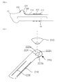
- Fig. 3 is a diagram describing a lesser trochanter securing device according to another embodiment of the present invention.
- Fig. 4 is a sectional view taken along a femoral shaft direction I-I' in the lesser trochanter securing device of Fig. 3 .
- the lesser trochanter securing device includes a basket portion 220 covering a lesser trochanter, and a buttress plating portion 210 joined to a lower edge of the basket portion 220 and extending toward a femoral shaft such that the buttress plating portion 210 is secured to the femoral shaft.
- the lesser trochanter securing device may further include an opening 224 disposed at the central region of the basket portion 220.
- the basket portion 220 may be variously modified according to the shape of the lesser trochanter.
- the basket portion 220 may be similar to a conical shell shape that is tapered in an upward direction.
- the center of the basket portion 220 may be disposed at a position shifted toward a femoral neck.
- An opening 224 may be disposed at the pinnacle area of the basket portion 220.
- the opening 224 may be disposed to be slightly sloped in a femoral diameter direction in the femoral shaft, such that the pinnacle area of the lesser trochanter can protrude.
- a plane connecting the pinnacle of the lesser trochanter, the intertrochanteric line, and the pectineal line may form a first plane, if excluding the pinnacle area of the lesser trochanter.
- a plane connecting the pinnacle of the lesser trochanter, the pectineal line, and the intertrochanteric line may form a second plane, if excluding the pinnacle area of the lesser trochanter.
- a plane connecting the femoral neck from the pinnacle of the lesser trochanter may form a third plane.
- the basket portion 220 may include at least one of a first correspondence plane 222a corresponding to the first plane, a second correspondence plane 222b corresponding to the second plane, and a third correspondence plane 222c corresponding to the third plane.
- the pinnacle area of the lesser trochanter may protrude through the opening 224.
- the cross section of the opening 224 may have a conical shape, but is not limited thereto. The cross section of the opening 224 may be modified in various shapes.
- the basket portion 220 and the buttress plating portion 210 may be joined by a smooth curved plane 226.
- the buttress plating portion 210 and the femoral shaft may be secured and joined by various fixing units 230.
- the fixing unit 230 may include at least one of a wire, a screw, a bone cement, and a fixation of the plate itself.
- the buttress plating portion 210 may include at least one hump 212 in the second buttressing curved plane. The hump 212 can secure the wire at a desired position and prevent slipping so that the wire is not released.
- Figs. 5 and 6 are perspective views describing a lesser trochanter securing device according to another embodiment of the present invention. A description about contents overlapped with those of Figs. 3 and 4 will be omitted.
- the lesser trochanter securing device includes a basket portion 220 covering a lesser trochanter, and a buttress plating portion 210 joined to a lower edge of the basket portion 220 and extending toward a femoral shaft such that the buttress plating portion 210 is secured and joined to the femoral shaft.
- the lesser trochanter securing device may further include an opening 224 disposed at the central region of the basket portion 220.
- An elastic body 240 may be disposed between the basket portion 220 and the lesser trochanter. Alternatively, the elastic body 240 may be inserted inside the basket portion 220.
- the elastic body 240 may have a truncated conical shape.
- the buttress plating unit 210 may include a slipping prevention unit 228 at the inner surface contacting the femoral shaft.
- the shape of the slipping prevention unit 228 may be variously modified.
- Fig. 7 is a diagram describing a lesser trochanter securing device according to still another embodiment of the present invention.
- the lesser trochanter securing device includes a basket portion 320 covering a lesser trochanter, and a buttress plating portion 310 joined to a lower edge of the basket portion 320 and extending toward a femoral shaft such that the buttress plating portion 310 is secured and joined to the femoral shaft.
- the basket portion 320 may be formed by being bent into a plurality of planes.
- the basket portion 320 may include first to sixth planes 322a to 322e around the pinnacle.
- a part of the first to sixth planes 322a to 322e may change a plane arrangement relationship, considering the outer shape of the lesser trochanter. Therefore, a part of the first to sixth planes 322a to 322e may be modified considering the outer shape of the lesser trochanter.
- six planes forming the basket portion 320 are taken as an example, the basket portion 320 may be modified without being limited thereto.
- the basket portion 320 may include a plane 322f that is not connected to the pinnacle.
- the basket portion 320 and the buttress plating portion 310 may be joined by different planes or curved planes.
- the buttress plating portion 310 may be configured by a plurality of planes or curved planes.
- the buttress plating portion 310 may extend toward the femoral shaft.
- the buttress plating portion 310 may be secured and joined to the femoral shaft by the fixing unit 330.
- the fixing unit 330 may include at least one of a wire, a screw, and a bone cement.
- the buttress plating unit 310 may include at least one hump 312 in the second buttressing curved plane.
- the hump 312 can secure the circlage wire at a desired position without slipping.
- Fig. 8 is a diagram describing a lesser trochanter securing device according to yet another embodiment of the present invention.
- the lesser trochanter securing device includes a basket portion 420 covering a lesser trochanter, and a buttress plating portion 410 secured and joined to a lower edge of the basket portion 420 and extending toward a femoral shaft such that the buttress plating portion 410 is secured and joined to the femoral shaft.
- the lesser trochanter securing device may further include an opening 424 disposed at the central region of the basket portion 420.
- the buttress plating portion 410 may include a wing 440 extending toward an intertrochanteric crest.
- the buttress plating portion 410 may extend from a lower edge of the basket portion 420.
- the wing 440 may extend in the direction of the intertrochanteric crest and connect to the intertrochanteric crest.
- the wing 440 may have a band shape with a curvature.
- the wing 440 may buttress the comminuted fracture fragment of the rear wall.
- the wing 440 may have a shape closely attached to the intertrochanteric crest.
- One end of the wing 440 may be joined to the basket portion 420 or the buttress plating portion 410, and the other end of the wing 440 may extend toward the intertrochanteric crest.
- At least one circular or oval through-hole 442 may be disposed at the other end of the wing 440.
- a screw, a wire, or a pin may be secured and joined to the intertrochanteric crest or the greater trochanter through the through-hole 442.
- at least one through-hole 429 may be provided at one end of the wing 440 or around the opening 424. The screw, the wire, or the pin may be secured and joined to the lesser trochanter through the through-hole 429.
- a hump 412 may be provided in the buttress plating portion 410.
- a fixing unit 430 may be disposed to cover the femoral shaft, and the slipping of the fixing unit 430 may be prevented by the hump 412 or gutter, the canal, or the like.
Landscapes
- Health & Medical Sciences (AREA)
- Orthopedic Medicine & Surgery (AREA)
- Life Sciences & Earth Sciences (AREA)
- Surgery (AREA)
- Animal Behavior & Ethology (AREA)
- General Health & Medical Sciences (AREA)
- Biomedical Technology (AREA)
- Heart & Thoracic Surgery (AREA)
- Engineering & Computer Science (AREA)
- Veterinary Medicine (AREA)
- Public Health (AREA)
- Medical Informatics (AREA)
- Neurology (AREA)
- Nuclear Medicine, Radiotherapy & Molecular Imaging (AREA)
- Molecular Biology (AREA)
- Oral & Maxillofacial Surgery (AREA)
- Transplantation (AREA)
- Cardiology (AREA)
- Vascular Medicine (AREA)
- Prostheses (AREA)
- Surgical Instruments (AREA)
Applications Claiming Priority (2)
| Application Number | Priority Date | Filing Date | Title |
|---|---|---|---|
| KR1020100078141A KR101219266B1 (ko) | 2010-08-13 | 2010-08-13 | 대퇴골 소전자와 주위를 견고하게 고정시켜서 인공 고관절 치환술이 가능할 수 있도록 안정적으로 보강하는 소전자 고정 장치 |
| PCT/KR2011/004473 WO2012020915A2 (ko) | 2010-08-13 | 2011-06-20 | 대퇴골 소전자와 주위를 견고하게 고정시켜서 인공 고관절 치환술이 가능할 수 있도록 안정적으로 보강하는 소전자 고정 장치 |
Publications (3)
| Publication Number | Publication Date |
|---|---|
| EP2606861A2 true EP2606861A2 (de) | 2013-06-26 |
| EP2606861A4 EP2606861A4 (de) | 2014-07-30 |
| EP2606861B1 EP2606861B1 (de) | 2020-02-26 |
Family
ID=45568000
Family Applications (1)
| Application Number | Title | Priority Date | Filing Date |
|---|---|---|---|
| EP11816531.5A Active EP2606861B1 (de) | 2010-08-13 | 2011-06-20 | Vorrichtung zur festen sicherung des kleinen rollhügels und seiner umgebung sowie zu seiner festigung zwecks ermöglichung eines chirurgischen eingriffs zum einsetzen einer künstlichen hüfte |
Country Status (6)
| Country | Link |
|---|---|
| US (1) | US9724142B2 (de) |
| EP (1) | EP2606861B1 (de) |
| JP (1) | JP2013538085A (de) |
| KR (1) | KR101219266B1 (de) |
| CN (1) | CN103298431A (de) |
| WO (1) | WO2012020915A2 (de) |
Families Citing this family (5)
| Publication number | Priority date | Publication date | Assignee | Title |
|---|---|---|---|---|
| US9549768B2 (en) | 2014-04-17 | 2017-01-24 | Biomet Manufacturing, Llc | Medical implant system for securing bone fragments |
| CN106618719B (zh) * | 2017-01-11 | 2023-04-18 | 海口市人民医院 | 经后侧股骨小粗隆复位空心拉力螺钉导针瞄准固定器 |
| RU2681245C1 (ru) * | 2018-02-22 | 2019-03-05 | Федеральное государственное бюджетное учреждение "Российский ордена Трудового Красного Знамени научно-исследовательский институт травматологии и ортопедии имени Р.Р. Вредена" Министерства здравоохранения Российской Федерации (ФГБУ "РНИИТО им. Р.Р. Вредена" Минздрава России) | Фиксатор для остеосинтеза большого вертела |
| JP2021010690A (ja) * | 2019-07-09 | 2021-02-04 | 株式会社ビー・アイ・テック | 骨固定プレート |
| AU2021202888B2 (en) * | 2020-05-26 | 2025-09-11 | Howmedica Osteonics Corp. | Medial trochanteric plate fixation |
Family Cites Families (22)
| Publication number | Priority date | Publication date | Assignee | Title |
|---|---|---|---|---|
| DE8808123U1 (de) * | 1988-06-24 | 1988-09-22 | Herzberg, Wolfgang, Dr. med., 2000 Wedel | Laschenschraube für die Osteosynthese pertrochantärer Frakturen |
| DE3840467A1 (de) * | 1988-12-01 | 1990-06-07 | Lieke Michael | Endoprothesenkomponenten fuer ein hueftgelenk tep |
| ATE103791T1 (de) * | 1990-03-01 | 1994-04-15 | Sulzer Medizinaltechnik Ag | Zementfreie kuenstliche hueftgelenkspfanne aus metall. |
| GB9206018D0 (en) * | 1992-03-19 | 1992-04-29 | Dall Desmond Meiring | Bone fixation system |
| CN2217965Y (zh) * | 1994-12-12 | 1996-01-24 | 马忠泰 | 非骨水泥人工髋关节 |
| NL9500256A (nl) * | 1995-02-10 | 1996-09-02 | Leuven K U Res & Dev | Prothese. |
| JP2942489B2 (ja) * | 1995-12-19 | 1999-08-30 | 株式会社ホムズ技研 | 他組織付着骨部の固定装置 |
| CN2253640Y (zh) * | 1995-12-21 | 1997-05-07 | 南汇县中心医院 | 股骨转子接骨内固定器 |
| US5797916A (en) * | 1996-12-10 | 1998-08-25 | Johnson & Johnson Professional, Inc. | Trochanteric reattachment cerclage device |
| EP0975705B1 (de) * | 1997-04-17 | 2002-03-13 | MERCK PATENT GmbH | Pufferlösungen für suspensionen, verwendbar zum chemisch-mechanischen polieren |
| DE19904436A1 (de) * | 1999-02-04 | 2000-08-10 | Ceramtec Ag | Hüftgelenkpfanne mit Kopplungselement zwischen Pfannengehäuse und Pfanneneinsatz |
| US7207993B1 (en) * | 2000-02-03 | 2007-04-24 | Pioneer Laboratories, Inc. | Apparatus and method for repairing the femur |
| US6338734B1 (en) * | 2000-03-14 | 2002-01-15 | Biomet, Inc. | Method and apparatus for trochanter fixation |
| US20050240187A1 (en) * | 2004-04-22 | 2005-10-27 | Huebner Randall J | Expanded fixation of bones |
| CN2638680Y (zh) * | 2003-06-24 | 2004-09-08 | 中南大学湘雅医院 | 股骨上段三维有限接触钢板 |
| US7229444B2 (en) * | 2004-08-25 | 2007-06-12 | Howmedica Osteonics Corp. | Trochanteric cerclage plate |
| BRPI0716133B8 (pt) * | 2006-08-15 | 2021-06-22 | Swissmedtechsolutions Ag | placa de retenção para trocanter |
| US8398687B2 (en) * | 2006-12-06 | 2013-03-19 | Amei Technologies, Inc. | Volar plate fixation device |
| KR100904088B1 (ko) * | 2009-01-09 | 2009-06-23 | 주식회사 코렌텍 | 인공 고관절용 대퇴스템 |
| KR100909580B1 (ko) * | 2009-01-21 | 2009-07-29 | 주식회사 코렌텍 | 주문형 인공 고관절용 대퇴스템 및 시술기구 제작방법 |
| KR100917715B1 (ko) * | 2009-03-13 | 2009-09-21 | 주식회사 코렌텍 | 주문형 인공 고관절 설계방법 및 이를 수행하는 프로그램을기록한 컴퓨터 판독가능한 기록매체 |
| US8808333B2 (en) * | 2009-07-06 | 2014-08-19 | Zimmer Gmbh | Periprosthetic bone plates |
-
2010
- 2010-08-13 KR KR1020100078141A patent/KR101219266B1/ko not_active Expired - Fee Related
-
2011
- 2011-06-20 US US13/813,235 patent/US9724142B2/en not_active Expired - Fee Related
- 2011-06-20 WO PCT/KR2011/004473 patent/WO2012020915A2/ko not_active Ceased
- 2011-06-20 EP EP11816531.5A patent/EP2606861B1/de active Active
- 2011-06-20 JP JP2013524770A patent/JP2013538085A/ja active Pending
- 2011-06-20 CN CN2011800498223A patent/CN103298431A/zh active Pending
Also Published As
| Publication number | Publication date |
|---|---|
| CN103298431A (zh) | 2013-09-11 |
| US9724142B2 (en) | 2017-08-08 |
| US20130138105A1 (en) | 2013-05-30 |
| KR20120015748A (ko) | 2012-02-22 |
| KR101219266B1 (ko) | 2013-01-18 |
| WO2012020915A3 (ko) | 2012-04-05 |
| EP2606861B1 (de) | 2020-02-26 |
| JP2013538085A (ja) | 2013-10-10 |
| EP2606861A4 (de) | 2014-07-30 |
| WO2012020915A2 (ko) | 2012-02-16 |
Similar Documents
| Publication | Publication Date | Title |
|---|---|---|
| JP7841884B2 (ja) | 近位圧迫のための弾性のあるアームを有する骨クリップ | |
| EP2730254B1 (de) | Doppelmodul-Hüftschaft | |
| CN102481193B (zh) | 假体 | |
| US7641699B2 (en) | Femoral head calcar loading prosthesis | |
| EP2777622B1 (de) | Oberschenkelkomponente für eine implantierbare Hüftgelenksprothese | |
| US9532818B2 (en) | Orthopedic nail and an orthopedic nail system | |
| US20140257512A1 (en) | Cementless Hip Resurfacing Prosthesis | |
| AU2018231150B2 (en) | Platform fracture fixation implants | |
| JPS5841856B2 (ja) | コシカンセツナイギシノダイタイブブン | |
| KR100607401B1 (ko) | 혈관보존형 대퇴골두 표면치환기구 | |
| EP2606861B1 (de) | Vorrichtung zur festen sicherung des kleinen rollhügels und seiner umgebung sowie zu seiner festigung zwecks ermöglichung eines chirurgischen eingriffs zum einsetzen einer künstlichen hüfte | |
| US11553949B2 (en) | Femoral fracture fixation device with posterior support portion | |
| US4851004A (en) | Implantation of articulating joint prosthesis | |
| US8252061B2 (en) | Femoral stem for artificial hip joint and artificial hip joint including the same | |
| US10610271B1 (en) | Orthopedic surgical implants | |
| US10245083B1 (en) | Method and device for minimizing the risk of future hip fractures | |
| CN212661905U (zh) | 一种股骨颈骨折固定装置 | |
| CN108210047B (zh) | 股骨近端骨折髓内固定装置 | |
| AU2009226723A1 (en) | Prosthetic body for an upper leg prosthetic | |
| KR20120102564A (ko) | 대퇴골 소전자와 주위를 견고하게 고정시켜서 인공 고관절 치환술이 가능할 수 있도록 안정적으로 보강하는 소전자 고정 장치 | |
| RU224986U1 (ru) | Диафизарная бедренная пластина | |
| CN102599971A (zh) | 一种股骨近端假体周围骨折内固定器 | |
| WO2022255970A1 (en) | Femur periprosthetic fracture fixation plate | |
| ITMI20100307A1 (it) | Protesi di collo femorale | |
| EP2886085B1 (de) | Doppelmodus-Schaft für orthopädische Prothese |
Legal Events
| Date | Code | Title | Description |
|---|---|---|---|
| PUAI | Public reference made under article 153(3) epc to a published international application that has entered the european phase |
Free format text: ORIGINAL CODE: 0009012 |
|
| 17P | Request for examination filed |
Effective date: 20130313 |
|
| AK | Designated contracting states |
Kind code of ref document: A2 Designated state(s): AL AT BE BG CH CY CZ DE DK EE ES FI FR GB GR HR HU IE IS IT LI LT LU LV MC MK MT NL NO PL PT RO RS SE SI SK SM TR |
|
| DAX | Request for extension of the european patent (deleted) | ||
| A4 | Supplementary search report drawn up and despatched |
Effective date: 20140627 |
|
| RIC1 | Information provided on ipc code assigned before grant |
Ipc: A61F 2/32 20060101ALI20140623BHEP Ipc: A61F 2/46 20060101AFI20140623BHEP Ipc: A61B 17/74 20060101ALI20140623BHEP |
|
| STAA | Information on the status of an ep patent application or granted ep patent |
Free format text: STATUS: EXAMINATION IS IN PROGRESS |
|
| 17Q | First examination report despatched |
Effective date: 20181114 |
|
| GRAP | Despatch of communication of intention to grant a patent |
Free format text: ORIGINAL CODE: EPIDOSNIGR1 |
|
| STAA | Information on the status of an ep patent application or granted ep patent |
Free format text: STATUS: GRANT OF PATENT IS INTENDED |
|
| INTG | Intention to grant announced |
Effective date: 20190926 |
|
| GRAS | Grant fee paid |
Free format text: ORIGINAL CODE: EPIDOSNIGR3 |
|
| GRAA | (expected) grant |
Free format text: ORIGINAL CODE: 0009210 |
|
| STAA | Information on the status of an ep patent application or granted ep patent |
Free format text: STATUS: THE PATENT HAS BEEN GRANTED |
|
| AK | Designated contracting states |
Kind code of ref document: B1 Designated state(s): AL AT BE BG CH CY CZ DE DK EE ES FI FR GB GR HR HU IE IS IT LI LT LU LV MC MK MT NL NO PL PT RO RS SE SI SK SM TR |
|
| REG | Reference to a national code |
Ref country code: GB Ref legal event code: FG4D |
|
| REG | Reference to a national code |
Ref country code: CH Ref legal event code: EP |
|
| REG | Reference to a national code |
Ref country code: AT Ref legal event code: REF Ref document number: 1236745 Country of ref document: AT Kind code of ref document: T Effective date: 20200315 |
|
| REG | Reference to a national code |
Ref country code: IE Ref legal event code: FG4D |
|
| REG | Reference to a national code |
Ref country code: DE Ref legal event code: R096 Ref document number: 602011065274 Country of ref document: DE |
|
| REG | Reference to a national code |
Ref country code: CH Ref legal event code: NV Representative=s name: KELLER AND PARTNER PATENTANWAELTE AG, CH |
|
| REG | Reference to a national code |
Ref country code: SE Ref legal event code: TRGR |
|
| PG25 | Lapsed in a contracting state [announced via postgrant information from national office to epo] |
Ref country code: FI Free format text: LAPSE BECAUSE OF FAILURE TO SUBMIT A TRANSLATION OF THE DESCRIPTION OR TO PAY THE FEE WITHIN THE PRESCRIBED TIME-LIMIT Effective date: 20200226 Ref country code: NO Free format text: LAPSE BECAUSE OF FAILURE TO SUBMIT A TRANSLATION OF THE DESCRIPTION OR TO PAY THE FEE WITHIN THE PRESCRIBED TIME-LIMIT Effective date: 20200526 Ref country code: RS Free format text: LAPSE BECAUSE OF FAILURE TO SUBMIT A TRANSLATION OF THE DESCRIPTION OR TO PAY THE FEE WITHIN THE PRESCRIBED TIME-LIMIT Effective date: 20200226 |
|
| PGFP | Annual fee paid to national office [announced via postgrant information from national office to epo] |
Ref country code: FR Payment date: 20200619 Year of fee payment: 10 Ref country code: CH Payment date: 20200618 Year of fee payment: 10 Ref country code: MC Payment date: 20200622 Year of fee payment: 10 |
|
| REG | Reference to a national code |
Ref country code: NL Ref legal event code: MP Effective date: 20200226 |
|
| REG | Reference to a national code |
Ref country code: LT Ref legal event code: MG4D |
|
| PG25 | Lapsed in a contracting state [announced via postgrant information from national office to epo] |
Ref country code: HR Free format text: LAPSE BECAUSE OF FAILURE TO SUBMIT A TRANSLATION OF THE DESCRIPTION OR TO PAY THE FEE WITHIN THE PRESCRIBED TIME-LIMIT Effective date: 20200226 Ref country code: BG Free format text: LAPSE BECAUSE OF FAILURE TO SUBMIT A TRANSLATION OF THE DESCRIPTION OR TO PAY THE FEE WITHIN THE PRESCRIBED TIME-LIMIT Effective date: 20200526 Ref country code: IS Free format text: LAPSE BECAUSE OF FAILURE TO SUBMIT A TRANSLATION OF THE DESCRIPTION OR TO PAY THE FEE WITHIN THE PRESCRIBED TIME-LIMIT Effective date: 20200626 Ref country code: LV Free format text: LAPSE BECAUSE OF FAILURE TO SUBMIT A TRANSLATION OF THE DESCRIPTION OR TO PAY THE FEE WITHIN THE PRESCRIBED TIME-LIMIT Effective date: 20200226 Ref country code: GR Free format text: LAPSE BECAUSE OF FAILURE TO SUBMIT A TRANSLATION OF THE DESCRIPTION OR TO PAY THE FEE WITHIN THE PRESCRIBED TIME-LIMIT Effective date: 20200527 |
|
| PGFP | Annual fee paid to national office [announced via postgrant information from national office to epo] |
Ref country code: GB Payment date: 20200625 Year of fee payment: 10 Ref country code: SE Payment date: 20200625 Year of fee payment: 10 |
|
| PG25 | Lapsed in a contracting state [announced via postgrant information from national office to epo] |
Ref country code: NL Free format text: LAPSE BECAUSE OF FAILURE TO SUBMIT A TRANSLATION OF THE DESCRIPTION OR TO PAY THE FEE WITHIN THE PRESCRIBED TIME-LIMIT Effective date: 20200226 |
|
| REG | Reference to a national code |
Ref country code: CH Ref legal event code: PFA Owner name: PARK, JEESUN, KR Free format text: FORMER OWNER: PARK, JEESUN, KR |
|
| PG25 | Lapsed in a contracting state [announced via postgrant information from national office to epo] |
Ref country code: SK Free format text: LAPSE BECAUSE OF FAILURE TO SUBMIT A TRANSLATION OF THE DESCRIPTION OR TO PAY THE FEE WITHIN THE PRESCRIBED TIME-LIMIT Effective date: 20200226 Ref country code: PT Free format text: LAPSE BECAUSE OF FAILURE TO SUBMIT A TRANSLATION OF THE DESCRIPTION OR TO PAY THE FEE WITHIN THE PRESCRIBED TIME-LIMIT Effective date: 20200719 Ref country code: DK Free format text: LAPSE BECAUSE OF FAILURE TO SUBMIT A TRANSLATION OF THE DESCRIPTION OR TO PAY THE FEE WITHIN THE PRESCRIBED TIME-LIMIT Effective date: 20200226 Ref country code: SM Free format text: LAPSE BECAUSE OF FAILURE TO SUBMIT A TRANSLATION OF THE DESCRIPTION OR TO PAY THE FEE WITHIN THE PRESCRIBED TIME-LIMIT Effective date: 20200226 Ref country code: EE Free format text: LAPSE BECAUSE OF FAILURE TO SUBMIT A TRANSLATION OF THE DESCRIPTION OR TO PAY THE FEE WITHIN THE PRESCRIBED TIME-LIMIT Effective date: 20200226 Ref country code: ES Free format text: LAPSE BECAUSE OF FAILURE TO SUBMIT A TRANSLATION OF THE DESCRIPTION OR TO PAY THE FEE WITHIN THE PRESCRIBED TIME-LIMIT Effective date: 20200226 Ref country code: RO Free format text: LAPSE BECAUSE OF FAILURE TO SUBMIT A TRANSLATION OF THE DESCRIPTION OR TO PAY THE FEE WITHIN THE PRESCRIBED TIME-LIMIT Effective date: 20200226 Ref country code: LT Free format text: LAPSE BECAUSE OF FAILURE TO SUBMIT A TRANSLATION OF THE DESCRIPTION OR TO PAY THE FEE WITHIN THE PRESCRIBED TIME-LIMIT Effective date: 20200226 Ref country code: CZ Free format text: LAPSE BECAUSE OF FAILURE TO SUBMIT A TRANSLATION OF THE DESCRIPTION OR TO PAY THE FEE WITHIN THE PRESCRIBED TIME-LIMIT Effective date: 20200226 |
|
| PGFP | Annual fee paid to national office [announced via postgrant information from national office to epo] |
Ref country code: DE Payment date: 20200826 Year of fee payment: 10 |
|
| REG | Reference to a national code |
Ref country code: AT Ref legal event code: MK05 Ref document number: 1236745 Country of ref document: AT Kind code of ref document: T Effective date: 20200226 |
|
| REG | Reference to a national code |
Ref country code: DE Ref legal event code: R097 Ref document number: 602011065274 Country of ref document: DE |
|
| PGFP | Annual fee paid to national office [announced via postgrant information from national office to epo] |
Ref country code: IT Payment date: 20200625 Year of fee payment: 10 |
|
| PLBE | No opposition filed within time limit |
Free format text: ORIGINAL CODE: 0009261 |
|
| STAA | Information on the status of an ep patent application or granted ep patent |
Free format text: STATUS: NO OPPOSITION FILED WITHIN TIME LIMIT |
|
| PG25 | Lapsed in a contracting state [announced via postgrant information from national office to epo] |
Ref country code: AT Free format text: LAPSE BECAUSE OF FAILURE TO SUBMIT A TRANSLATION OF THE DESCRIPTION OR TO PAY THE FEE WITHIN THE PRESCRIBED TIME-LIMIT Effective date: 20200226 |
|
| 26N | No opposition filed |
Effective date: 20201127 |
|
| PG25 | Lapsed in a contracting state [announced via postgrant information from national office to epo] |
Ref country code: PL Free format text: LAPSE BECAUSE OF FAILURE TO SUBMIT A TRANSLATION OF THE DESCRIPTION OR TO PAY THE FEE WITHIN THE PRESCRIBED TIME-LIMIT Effective date: 20200226 Ref country code: SI Free format text: LAPSE BECAUSE OF FAILURE TO SUBMIT A TRANSLATION OF THE DESCRIPTION OR TO PAY THE FEE WITHIN THE PRESCRIBED TIME-LIMIT Effective date: 20200226 |
|
| PG25 | Lapsed in a contracting state [announced via postgrant information from national office to epo] |
Ref country code: LU Free format text: LAPSE BECAUSE OF NON-PAYMENT OF DUE FEES Effective date: 20200620 |
|
| REG | Reference to a national code |
Ref country code: BE Ref legal event code: MM Effective date: 20200630 |
|
| PG25 | Lapsed in a contracting state [announced via postgrant information from national office to epo] |
Ref country code: IE Free format text: LAPSE BECAUSE OF NON-PAYMENT OF DUE FEES Effective date: 20200620 |
|
| PG25 | Lapsed in a contracting state [announced via postgrant information from national office to epo] |
Ref country code: BE Free format text: LAPSE BECAUSE OF NON-PAYMENT OF DUE FEES Effective date: 20200630 |
|
| REG | Reference to a national code |
Ref country code: DE Ref legal event code: R119 Ref document number: 602011065274 Country of ref document: DE |
|
| REG | Reference to a national code |
Ref country code: SE Ref legal event code: EUG |
|
| PG25 | Lapsed in a contracting state [announced via postgrant information from national office to epo] |
Ref country code: MC Free format text: LAPSE BECAUSE OF NON-PAYMENT OF DUE FEES Effective date: 20210630 |
|
| REG | Reference to a national code |
Ref country code: CH Ref legal event code: PL |
|
| GBPC | Gb: european patent ceased through non-payment of renewal fee |
Effective date: 20210620 |
|
| PG25 | Lapsed in a contracting state [announced via postgrant information from national office to epo] |
Ref country code: LI Free format text: LAPSE BECAUSE OF NON-PAYMENT OF DUE FEES Effective date: 20210630 Ref country code: GB Free format text: LAPSE BECAUSE OF NON-PAYMENT OF DUE FEES Effective date: 20210620 Ref country code: DE Free format text: LAPSE BECAUSE OF NON-PAYMENT OF DUE FEES Effective date: 20220101 Ref country code: CH Free format text: LAPSE BECAUSE OF NON-PAYMENT OF DUE FEES Effective date: 20210630 |
|
| PG25 | Lapsed in a contracting state [announced via postgrant information from national office to epo] |
Ref country code: TR Free format text: LAPSE BECAUSE OF FAILURE TO SUBMIT A TRANSLATION OF THE DESCRIPTION OR TO PAY THE FEE WITHIN THE PRESCRIBED TIME-LIMIT Effective date: 20200226 Ref country code: SE Free format text: LAPSE BECAUSE OF NON-PAYMENT OF DUE FEES Effective date: 20210621 Ref country code: MT Free format text: LAPSE BECAUSE OF FAILURE TO SUBMIT A TRANSLATION OF THE DESCRIPTION OR TO PAY THE FEE WITHIN THE PRESCRIBED TIME-LIMIT Effective date: 20200226 Ref country code: FR Free format text: LAPSE BECAUSE OF NON-PAYMENT OF DUE FEES Effective date: 20210630 Ref country code: CY Free format text: LAPSE BECAUSE OF FAILURE TO SUBMIT A TRANSLATION OF THE DESCRIPTION OR TO PAY THE FEE WITHIN THE PRESCRIBED TIME-LIMIT Effective date: 20200226 |
|
| PG25 | Lapsed in a contracting state [announced via postgrant information from national office to epo] |
Ref country code: MK Free format text: LAPSE BECAUSE OF FAILURE TO SUBMIT A TRANSLATION OF THE DESCRIPTION OR TO PAY THE FEE WITHIN THE PRESCRIBED TIME-LIMIT Effective date: 20200226 Ref country code: AL Free format text: LAPSE BECAUSE OF FAILURE TO SUBMIT A TRANSLATION OF THE DESCRIPTION OR TO PAY THE FEE WITHIN THE PRESCRIBED TIME-LIMIT Effective date: 20200226 |
|
| PG25 | Lapsed in a contracting state [announced via postgrant information from national office to epo] |
Ref country code: IT Free format text: LAPSE BECAUSE OF NON-PAYMENT OF DUE FEES Effective date: 20210620 |