EP2607076A1 - Film en perspective et procédé de préparation associé - Google Patents
Film en perspective et procédé de préparation associé Download PDFInfo
- Publication number
- EP2607076A1 EP2607076A1 EP11817677.5A EP11817677A EP2607076A1 EP 2607076 A1 EP2607076 A1 EP 2607076A1 EP 11817677 A EP11817677 A EP 11817677A EP 2607076 A1 EP2607076 A1 EP 2607076A1
- Authority
- EP
- European Patent Office
- Prior art keywords
- transparent film
- film
- printed
- layer
- liner
- Prior art date
- Legal status (The legal status is an assumption and is not a legal conclusion. Google has not performed a legal analysis and makes no representation as to the accuracy of the status listed.)
- Withdrawn
Links
Images


Classifications
-
- B—PERFORMING OPERATIONS; TRANSPORTING
- B32—LAYERED PRODUCTS
- B32B—LAYERED PRODUCTS, i.e. PRODUCTS BUILT-UP OF STRATA OF FLAT OR NON-FLAT, e.g. CELLULAR OR HONEYCOMB, FORM
- B32B7/00—Layered products characterised by the relation between layers; Layered products characterised by the relative orientation of features between layers, or by the relative values of a measurable parameter between layers, i.e. products comprising layers having different physical, chemical or physicochemical properties; Layered products characterised by the interconnection of layers
- B32B7/04—Interconnection of layers
- B32B7/12—Interconnection of layers using interposed adhesives or interposed materials with bonding properties
-
- B—PERFORMING OPERATIONS; TRANSPORTING
- B32—LAYERED PRODUCTS
- B32B—LAYERED PRODUCTS, i.e. PRODUCTS BUILT-UP OF STRATA OF FLAT OR NON-FLAT, e.g. CELLULAR OR HONEYCOMB, FORM
- B32B7/00—Layered products characterised by the relation between layers; Layered products characterised by the relative orientation of features between layers, or by the relative values of a measurable parameter between layers, i.e. products comprising layers having different physical, chemical or physicochemical properties; Layered products characterised by the interconnection of layers
- B32B7/02—Physical, chemical or physicochemical properties
- B32B7/023—Optical properties
-
- B—PERFORMING OPERATIONS; TRANSPORTING
- B32—LAYERED PRODUCTS
- B32B—LAYERED PRODUCTS, i.e. PRODUCTS BUILT-UP OF STRATA OF FLAT OR NON-FLAT, e.g. CELLULAR OR HONEYCOMB, FORM
- B32B27/00—Layered products comprising a layer of synthetic resin
-
- B—PERFORMING OPERATIONS; TRANSPORTING
- B32—LAYERED PRODUCTS
- B32B—LAYERED PRODUCTS, i.e. PRODUCTS BUILT-UP OF STRATA OF FLAT OR NON-FLAT, e.g. CELLULAR OR HONEYCOMB, FORM
- B32B27/00—Layered products comprising a layer of synthetic resin
- B32B27/06—Layered products comprising a layer of synthetic resin as the main or only constituent of a layer, which is next to another layer of the same or of a different material
- B32B27/08—Layered products comprising a layer of synthetic resin as the main or only constituent of a layer, which is next to another layer of the same or of a different material of synthetic resin
-
- B—PERFORMING OPERATIONS; TRANSPORTING
- B32—LAYERED PRODUCTS
- B32B—LAYERED PRODUCTS, i.e. PRODUCTS BUILT-UP OF STRATA OF FLAT OR NON-FLAT, e.g. CELLULAR OR HONEYCOMB, FORM
- B32B27/00—Layered products comprising a layer of synthetic resin
- B32B27/06—Layered products comprising a layer of synthetic resin as the main or only constituent of a layer, which is next to another layer of the same or of a different material
- B32B27/10—Layered products comprising a layer of synthetic resin as the main or only constituent of a layer, which is next to another layer of the same or of a different material of paper or cardboard
-
- B—PERFORMING OPERATIONS; TRANSPORTING
- B32—LAYERED PRODUCTS
- B32B—LAYERED PRODUCTS, i.e. PRODUCTS BUILT-UP OF STRATA OF FLAT OR NON-FLAT, e.g. CELLULAR OR HONEYCOMB, FORM
- B32B27/00—Layered products comprising a layer of synthetic resin
- B32B27/18—Layered products comprising a layer of synthetic resin characterised by the use of special additives
- B32B27/20—Layered products comprising a layer of synthetic resin characterised by the use of special additives using fillers, pigments, thixotroping agents
-
- B—PERFORMING OPERATIONS; TRANSPORTING
- B32—LAYERED PRODUCTS
- B32B—LAYERED PRODUCTS, i.e. PRODUCTS BUILT-UP OF STRATA OF FLAT OR NON-FLAT, e.g. CELLULAR OR HONEYCOMB, FORM
- B32B27/00—Layered products comprising a layer of synthetic resin
- B32B27/28—Layered products comprising a layer of synthetic resin comprising synthetic resins not wholly covered by any one of the sub-groups B32B27/30 - B32B27/42
-
- B—PERFORMING OPERATIONS; TRANSPORTING
- B32—LAYERED PRODUCTS
- B32B—LAYERED PRODUCTS, i.e. PRODUCTS BUILT-UP OF STRATA OF FLAT OR NON-FLAT, e.g. CELLULAR OR HONEYCOMB, FORM
- B32B27/00—Layered products comprising a layer of synthetic resin
- B32B27/30—Layered products comprising a layer of synthetic resin comprising vinyl (co)polymers; comprising acrylic (co)polymers
- B32B27/304—Layered products comprising a layer of synthetic resin comprising vinyl (co)polymers; comprising acrylic (co)polymers comprising vinyl halide (co)polymers, e.g. PVC, PVDC, PVF, PVDF
-
- B—PERFORMING OPERATIONS; TRANSPORTING
- B32—LAYERED PRODUCTS
- B32B—LAYERED PRODUCTS, i.e. PRODUCTS BUILT-UP OF STRATA OF FLAT OR NON-FLAT, e.g. CELLULAR OR HONEYCOMB, FORM
- B32B27/00—Layered products comprising a layer of synthetic resin
- B32B27/32—Layered products comprising a layer of synthetic resin comprising polyolefins
-
- B—PERFORMING OPERATIONS; TRANSPORTING
- B32—LAYERED PRODUCTS
- B32B—LAYERED PRODUCTS, i.e. PRODUCTS BUILT-UP OF STRATA OF FLAT OR NON-FLAT, e.g. CELLULAR OR HONEYCOMB, FORM
- B32B27/00—Layered products comprising a layer of synthetic resin
- B32B27/36—Layered products comprising a layer of synthetic resin comprising polyesters
-
- B—PERFORMING OPERATIONS; TRANSPORTING
- B32—LAYERED PRODUCTS
- B32B—LAYERED PRODUCTS, i.e. PRODUCTS BUILT-UP OF STRATA OF FLAT OR NON-FLAT, e.g. CELLULAR OR HONEYCOMB, FORM
- B32B37/00—Methods or apparatus for laminating, e.g. by curing or by ultrasonic bonding
- B32B37/12—Methods or apparatus for laminating, e.g. by curing or by ultrasonic bonding characterised by using adhesives
-
- B—PERFORMING OPERATIONS; TRANSPORTING
- B32—LAYERED PRODUCTS
- B32B—LAYERED PRODUCTS, i.e. PRODUCTS BUILT-UP OF STRATA OF FLAT OR NON-FLAT, e.g. CELLULAR OR HONEYCOMB, FORM
- B32B38/00—Ancillary operations in connection with laminating processes
- B32B38/14—Printing or colouring
-
- B—PERFORMING OPERATIONS; TRANSPORTING
- B32—LAYERED PRODUCTS
- B32B—LAYERED PRODUCTS, i.e. PRODUCTS BUILT-UP OF STRATA OF FLAT OR NON-FLAT, e.g. CELLULAR OR HONEYCOMB, FORM
- B32B38/00—Ancillary operations in connection with laminating processes
- B32B38/14—Printing or colouring
- B32B38/145—Printing
-
- B—PERFORMING OPERATIONS; TRANSPORTING
- B32—LAYERED PRODUCTS
- B32B—LAYERED PRODUCTS, i.e. PRODUCTS BUILT-UP OF STRATA OF FLAT OR NON-FLAT, e.g. CELLULAR OR HONEYCOMB, FORM
- B32B7/00—Layered products characterised by the relation between layers; Layered products characterised by the relative orientation of features between layers, or by the relative values of a measurable parameter between layers, i.e. products comprising layers having different physical, chemical or physicochemical properties; Layered products characterised by the interconnection of layers
- B32B7/03—Layered products characterised by the relation between layers; Layered products characterised by the relative orientation of features between layers, or by the relative values of a measurable parameter between layers, i.e. products comprising layers having different physical, chemical or physicochemical properties; Layered products characterised by the interconnection of layers with respect to the orientation of features
-
- B—PERFORMING OPERATIONS; TRANSPORTING
- B32—LAYERED PRODUCTS
- B32B—LAYERED PRODUCTS, i.e. PRODUCTS BUILT-UP OF STRATA OF FLAT OR NON-FLAT, e.g. CELLULAR OR HONEYCOMB, FORM
- B32B7/00—Layered products characterised by the relation between layers; Layered products characterised by the relative orientation of features between layers, or by the relative values of a measurable parameter between layers, i.e. products comprising layers having different physical, chemical or physicochemical properties; Layered products characterised by the interconnection of layers
- B32B7/04—Interconnection of layers
- B32B7/05—Interconnection of layers the layers not being connected over the whole surface, e.g. discontinuous connection or patterned connection
-
- B—PERFORMING OPERATIONS; TRANSPORTING
- B32—LAYERED PRODUCTS
- B32B—LAYERED PRODUCTS, i.e. PRODUCTS BUILT-UP OF STRATA OF FLAT OR NON-FLAT, e.g. CELLULAR OR HONEYCOMB, FORM
- B32B7/00—Layered products characterised by the relation between layers; Layered products characterised by the relative orientation of features between layers, or by the relative values of a measurable parameter between layers, i.e. products comprising layers having different physical, chemical or physicochemical properties; Layered products characterised by the interconnection of layers
- B32B7/04—Interconnection of layers
- B32B7/10—Interconnection of layers at least one layer having inter-reactive properties
-
- B—PERFORMING OPERATIONS; TRANSPORTING
- B32—LAYERED PRODUCTS
- B32B—LAYERED PRODUCTS, i.e. PRODUCTS BUILT-UP OF STRATA OF FLAT OR NON-FLAT, e.g. CELLULAR OR HONEYCOMB, FORM
- B32B7/00—Layered products characterised by the relation between layers; Layered products characterised by the relative orientation of features between layers, or by the relative values of a measurable parameter between layers, i.e. products comprising layers having different physical, chemical or physicochemical properties; Layered products characterised by the interconnection of layers
- B32B7/04—Interconnection of layers
- B32B7/12—Interconnection of layers using interposed adhesives or interposed materials with bonding properties
- B32B7/14—Interconnection of layers using interposed adhesives or interposed materials with bonding properties applied in spaced arrangements, e.g. in stripes
-
- B—PERFORMING OPERATIONS; TRANSPORTING
- B32—LAYERED PRODUCTS
- B32B—LAYERED PRODUCTS, i.e. PRODUCTS BUILT-UP OF STRATA OF FLAT OR NON-FLAT, e.g. CELLULAR OR HONEYCOMB, FORM
- B32B9/00—Layered products comprising a layer of a particular substance not covered by groups B32B11/00 - B32B29/00
-
- B—PERFORMING OPERATIONS; TRANSPORTING
- B41—PRINTING; LINING MACHINES; TYPEWRITERS; STAMPS
- B41M—PRINTING, DUPLICATING, MARKING, OR COPYING PROCESSES; COLOUR PRINTING
- B41M3/00—Printing processes to produce particular kinds of printed work, e.g. patterns
- B41M3/008—Sequential or multiple printing, e.g. on previously printed background; Mirror printing; Recto-verso printing; using a combination of different printing techniques; Printing of patterns visible in reflection and by transparency; by superposing printed artifacts
-
- B—PERFORMING OPERATIONS; TRANSPORTING
- B32—LAYERED PRODUCTS
- B32B—LAYERED PRODUCTS, i.e. PRODUCTS BUILT-UP OF STRATA OF FLAT OR NON-FLAT, e.g. CELLULAR OR HONEYCOMB, FORM
- B32B2307/00—Properties of the layers or laminate
- B32B2307/40—Properties of the layers or laminate having particular optical properties
- B32B2307/402—Coloured
-
- B—PERFORMING OPERATIONS; TRANSPORTING
- B32—LAYERED PRODUCTS
- B32B—LAYERED PRODUCTS, i.e. PRODUCTS BUILT-UP OF STRATA OF FLAT OR NON-FLAT, e.g. CELLULAR OR HONEYCOMB, FORM
- B32B2307/00—Properties of the layers or laminate
- B32B2307/40—Properties of the layers or laminate having particular optical properties
- B32B2307/412—Transparent
-
- B—PERFORMING OPERATIONS; TRANSPORTING
- B32—LAYERED PRODUCTS
- B32B—LAYERED PRODUCTS, i.e. PRODUCTS BUILT-UP OF STRATA OF FLAT OR NON-FLAT, e.g. CELLULAR OR HONEYCOMB, FORM
- B32B2309/00—Parameters for the laminating or treatment process; Apparatus details
- B32B2309/08—Dimensions, e.g. volume
- B32B2309/10—Dimensions, e.g. volume linear, e.g. length, distance, width
- B32B2309/105—Thickness
-
- B—PERFORMING OPERATIONS; TRANSPORTING
- B32—LAYERED PRODUCTS
- B32B—LAYERED PRODUCTS, i.e. PRODUCTS BUILT-UP OF STRATA OF FLAT OR NON-FLAT, e.g. CELLULAR OR HONEYCOMB, FORM
- B32B2317/00—Animal or vegetable based
- B32B2317/12—Paper, e.g. cardboard
-
- B—PERFORMING OPERATIONS; TRANSPORTING
- B32—LAYERED PRODUCTS
- B32B—LAYERED PRODUCTS, i.e. PRODUCTS BUILT-UP OF STRATA OF FLAT OR NON-FLAT, e.g. CELLULAR OR HONEYCOMB, FORM
- B32B38/00—Ancillary operations in connection with laminating processes
- B32B38/0008—Electrical discharge treatment, e.g. corona, plasma treatment; wave energy or particle radiation
-
- Y—GENERAL TAGGING OF NEW TECHNOLOGICAL DEVELOPMENTS; GENERAL TAGGING OF CROSS-SECTIONAL TECHNOLOGIES SPANNING OVER SEVERAL SECTIONS OF THE IPC; TECHNICAL SUBJECTS COVERED BY FORMER USPC CROSS-REFERENCE ART COLLECTIONS [XRACs] AND DIGESTS
- Y10—TECHNICAL SUBJECTS COVERED BY FORMER USPC
- Y10T—TECHNICAL SUBJECTS COVERED BY FORMER US CLASSIFICATION
- Y10T428/00—Stock material or miscellaneous articles
- Y10T428/24—Structurally defined web or sheet [e.g., overall dimension, etc.]
- Y10T428/24802—Discontinuous or differential coating, impregnation or bond [e.g., artwork, printing, retouched photograph, etc.]
Definitions
- This invention relates to a kind of bi-viewable perspective film that can be used for advertising, decorating, and other such purposes, and is especially suited for use on glass surfaces and other such transparent substrates.
- the subject "bi-viewable perspective film” as used herein pertains to a kind of light permeable film that allows an image printed on one surface to be viewed on either sides of the film.
- the one-way vision vinyl which is created using a layer of printable film (usually PVC).
- PVC a layer of printable film
- the liner aka. release paper
- the vinyl is perforated with circular perforations spreading evenly over the PVC-adhesive-liner complex, each hole penetrating both the PVC printing film layer and the adhesive layer.
- This type of vinyl is created using perforation machines that perforate the PVC-adhesive-liner complex with evenly spaced circular holes.
- the now-porous liner is then removed and replaced with a new un-perforated liner, forming a new three layered structure where only the PVC and adhesive layers are perforated.
- This type of vinyl is widely used in advertising, especially on glass or similarly transparent surfaces. If the vinyl is placed on the windows of a car, only the image printed upon the vinyl will be viewable from the outside whereas an unobstructed view of the outer environment can be obtained from within the vehicle (an effective optical illusion created by the perforations on the PVC layer of the vinyl).
- This invention concerns a kind of translucent fabric produced by the directly printing of a colour rendering layer onto a transparent film. This allows for an image printed on the transparent film (already pre-printed with the colour rendering layer) to display with stunning precision while being visible to both viewable sides (front and back), while also resolving the various production efficiency issues aforementioned.
- the "colour rendering layer” as used herein pertains to a layer that is placed onto the transparent film in order to provide contrast for any additional prints.
- the application of such a method allows for a image printed on the transparent film to look as if it's printed on a solid perforated vinyl, without there being any physical perforations on the film.
- the "colour rendering layer” will be referred to as the "CRL” hereinafter for the sake of simplicity.
- This invention may also include the addition of a convenient, sturdy, and widely applicable transparent pressure-sensitive adhesive layer onto the transparent film-CRL complex. Further replacement of the pressure-sensitive adhesive layer with electrostatic adhesion technology will result in an even more reusable, convenient, and environmentally product as a part of this invention.
- the aforementioned bi-viewable perspective film is characterized by the inclusion of a transparent film, the CLR, and the liner.
- the CRL is set upon the aforementioned transparent film, which is adhered to the liner in with various adhesive techniques.
- the CRL is a layer that is set upon the transparent film using one of multiple different mediums including but not limited to white ink, fluorescence ink, or any other colours and similar ink-like mediums that is able to achieve sufficient contrast, either by printing, pressing, stamping, or other similar adhesive processes.
- the CRL also contains various repeating apertures called the light-transmitting zones. These zones are not physical constructs, and simply refer to the places where there is an absence of CRL presence. Within each of the light-transmitting zones, one can clearly see through the transparent film onto the other side.
- the aforementioned light-transmitting zones may be expressed in as apertures upon a CRL layer (for example, evenly spaced circular holes upon a white CRL layer), or the CRL layer may be smaller repeating patterns and shapes, where the space between each shape forms the body of the light-transmitting zones (for example, evenly printed solid white circles on the transparent film, where the spaces between the circles makes up the light-transmitting zones).
- a CRL layer for example, evenly spaced circular holes upon a white CRL layer
- the CRL layer may be smaller repeating patterns and shapes, where the space between each shape forms the body of the light-transmitting zones (for example, evenly printed solid white circles on the transparent film, where the spaces between the circles makes up the light-transmitting zones).
- the aforementioned bi-viewable perspective film also partake various different structures in order to cater to different user preferences via the use of numerous adhesive techniques, namely by use of either a pressure-sensitive transparent adhesive layer or the aforementioned electrostatic adhesion technique, when the main body of the transparent film is adhered onto the liner.
- an additional light filtering layer can also be added.
- the "light filtering layer” as used herein pertains to a layer that is virtually the same as the CRL with the exception that its function is to solidify the colours of the images printed on the bi-view perspective film.
- the “light filtering layer” (hereinafter referred to as the "LFL”) usually uses solid or darker colours for the sake of solidity.
- the LFL and the CRL are exact duplicates (ie. position and presence of light transmitting zones, shape of light transmitting zones). Note that the inclusion of a LFL is optional.
- the aforementioned transparent film is corona treated up to 36-56 dynes with a high voltage current prior to the start of step (1).
- Protective fluid can also be applied to the surface of the CRL to achieve this end.
- a protective liquid is applied to the surface of the printed colour rendering layer upon the completion of step (1), and only after that can step (2) proceed.
- the next optional step is variable depending on the applicable printing surface.
- the "printing surface” as used herein pertains to the surface in the finished bi-viewable perspective film product that can be printed on, and as such the printing surface is naturally opposite to the side adhered to the liner, since the liner cannot be printed upon.
- the printing surface is also hereby designated as the "front” of the film, whereas the “back” of the film is the side adhered to the liner, upon which nothing can be printed.
- a facilitative ink absorption and colour enhancement agent is applied to the printing surface. If the transparent film is the printing surface of the bi-viewable perspective film, then the facilitative ink absorption and colour enhancement agent should be applied to the surface of the transparent film prior to step (1). If the surface of the CRL is to be the printing surface of the bi-viewable perspective film, then the facilitative ink absorption and colour enhancement agent should be applied to the surface of the CRL upon the completion of step (1) before step (2) commences.
- an additional step involving the adhesion of the LFL in a similar manner to the CRL can be added after the completion of step (1) before step (2) commences.
- the body of the CRL-transparent film complex (with or without the LFL) can be adhered to the liner with a variety of different medium and/or techniques depending on the type of transparent film used.
- a transparent pressure-sensitive adhesives layer can be applied to the liner. Since the layer of adhesives is transparent, it will not impede light transmission. After the liner with the pressure-sensitive adhesives layer applied is pressed onto the transparent film complex, the adhesives will adhere to the transparent film more strongly than it does the liner. Thus when one peels off the liner, the pressure-sensitive adhesives is retained by the body of the bi-viewable perspective film. If the transparent film is made using electrostatic technology, there would be no need for an adhesives layer and the liner would simply be pressed onto the transparent film to form the bi-viewable perspective film.
- the Bi-viewable perspective films' manufacture process manifests in a variety of different ways that define and distinguish the bi-viewable perspective film from other outdoor printing medium.
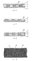
- Schematic components are (1) Transparent film, (2) Colour rendering layer, (21) Light filtering zones, (3) Liner, (4) Light filtering layer, (5) Transparent pressure-sensitive adhesives layer.
- Figures one through eleven illustrate the constituents of the bi-viewable perspective film.
- a transparent film (1) is printed with the CRL (2) that is riddled with light-transmitting zones (21) and attached to the liner (3).
- This allows prints to obtain a higher resolution while still retaining a degree of light permeability. Since the locations with light-transmitting zones (21) are still covered by the transparent film (1), there is still ink absorption and thus the printing is able to achieve a high level of precision in spite of its light permeability.
- This also allows the image to be viewed at around 50% resolution from the back of the film through the ink retained by the transparent film (1) at the locations of the light-transmitting zones (21).
- the aforementioned light-transmitting zones (21) may be expressed in as apertures upon a CRL (2) layer (for example, evenly spaced circular holes upon a white CRL (2)) or the CRL (2) layer may be smaller repeating patterns and shapes, where the space between each shape forms the body of the light-transmitting zones (21) (for example, evenly printed solid white circles on the transparent film (1), where the spaces between the circles makes up the light-transmitting zones (21)).
- Fig. 9 , Fig 10, and Fig 11 for three of the numerous possible scenarios.
- the colour rendering layer (2) is adhered to the transparent film (1) using printing methods. This allows for a high production speed of 50-200 meters/minute. This method is also very cost effective, results in less defective products per batch, and does not generate as much waste as does traditional perforation techniques through conservation of liner (3) material.
- the light-transmitting zones (21) can furthermore be spread out on the CRL (2) according to user specifications in any shape that is desired.
- the thickness range of the colour rendering layer (2) is 1 ⁇ 20 ⁇ m, allowing for both effective visual enhancement while also ensuring that the transparent film (1), if electrostatic, would readily adhere to targeted surfaces.
- the bi-viewable perspective film can be printed with the desired images.
- the bi-viewable perspective film can be easily applied to the desired surface via either electrostatic techniques or a transparent pressure-sensitive adhesives layer (5).
- the printed colour rendering layer (2) can be printed with a wide variety of medium including but not limited to white ink, fluorescent ink, or with any other colours (though in practice, white is most commonly used).
- the transparent film (1) itself can also be made from a wide variety of mediums, including but limited to PVC, PE, or PET membranes, and a facilitative ink absorption and colour enhancement agent could also applied to its surface to facilitate ink vibrancy and retention. Moreover since the transparent film (1) is not actually perforated, the fabric is very resilient, the printed images will have high accuracy, the film will be easier to apply and remove, and there will be no pollution due to dust clutters accumulating within the perforations.
- the transparent film (1) can be adhered to the liner (3) in a variety of ways.
- a transparent pressure-sensitive adhesive layer (5) If it is adhered via a transparent pressure-sensitive adhesive layer (5), then removable adhesives should be used to prevent residual glue. However to further lower production costs as per request from customers, normal glue is sometimes used as well.
- When applying simply tear off the liner (3) and then press the transparent film on the glass, vehicle windows or other transparent panels via the transparent adhesive layer (5). Not only will it adhere firmly, it is convenient for use, replacement, and is applicable both indoors and outdoors. Since the adhesive layer is transparent, it will not have any impact on light transmission and consequently the perspective effects of the transparent film (1).
- the transparent film (1) used is a type of static film, it will be adhered to the liner (3) via static electricity. When using, tear off the liner (3) and press it onto glass, vehicle windows, or other types of transparent panels and it will adhere through static electricity. This method is environmentally friendly, while also being easier to apply and remove and more cost effective, while also rendering the film reusable without leaving any glue residue. Both sides of a static film can be used as the adhesive surface, allowing for a wide range of applications (especially in-doors).
- the colour rendering layer (2) can be printed on either the front or back of the transparent film, with back being defined as the layer closest to the liner (3) and front defined as the opposite direction.
- the transparent film (1) used is a static
- the colour rendering layer (2) being printed on the surface of the transparent film (1) refers to it being printed on the opposite side of where the liner (3) attaches with the transparent film (1), whereas if the colour rendering layer (2) is being printed on the back of the transparent film (1), it is being printed in-between the liner (3) and the transparent film (1).
- a light filtering layer (4) is printed also printed on the transparent film in a way as to correspond exactly with the colour rendering layer (2).
- the light-transmitting zones are also distributed throughout the light filtering layer (4), and that the light transmitting zones of the light filtering layer (4) corresponds exactly with the light transmitting zones (21) of the colour rendering layer (2) in every-which way, be it shape, location, quantity... etc.
- the light filtering layer (4) is printed on the colour rendering layer (2) or on the opposite side of the transparent film (1) from the colour rendering layer (2), though it is primarily printed on the side of the transparent film (1) that will not be printed on.
- the light filtering layer (4) is printed upon the transparent film (1) with black or another solid type of colour, with black being the most commonly used.
- FIG. 1 Figures one through four detail possible scenarios where a transparent pressure-sensitive adhesives layer is used either with or without a LFL.
- Figure 1 shows a possible scenario.
- the transparent film (1) is adhered to the liner (3) with the transparent pressure-sensitive adhesive layer (5).
- the liner (3) can be PE coated release paper or PET release film.
- the CRL (2) is pressed on the surface of the transparent film (1) where the transparent film (1) is pressed against the liner (3), between the transparent film (1) and the transparent pressure-sensitive adhesives layer (5).
- the preparation method is thus; if the transparent film (1) is PVC film, no high-voltage corona treatment is necessary and the CRL (2) can be printed on directly.
- the transparent film (1) is PE or PET film, or another kind of transparent plastic film
- high-voltage corona treatment will need to be carried out first at a voltage between 36 and 56 dynes (38 dynes preferred), after which the CRL (2) can be applied on the treated surface of the transparent film (1).
- the CRL (2) When printing the CRL (2), ensure that it is between 1 ⁇ m -20 ⁇ m in thickness. Also ensure that the light-transmitting zones (21) are spread over the CRL (2) evenly using appropriate printing techniques (usually intaglio printing techniques). Apply now a protective liquid layer (not indicated in the figure) to the printed CRL (2) to prevent it from peeling off easily.
- the transparent pressure-sensitive adhesive layer (5) to the surface of the transparent film (1) on which the CRL (2) resides, or apply the transparent pressure-sensitive adhesives onto the liner (3) itself.
- the side of the transparent film (1) that is not printed with CRL (2) (aka. the front of the film) is used as the printing surface.
- the transparent pressure-sensitive adhesives layer shown in the figure is flat, in actuality the adhesives fill the entire light-transmitting zone (21) of the CRL (2) after being compounded forcefully by the laminating machine. Note that the drawings are not to scale, and that in reality the CRL (2) is a significantly thinner layer than the transparent film (1).
- FIG 2 s a scenario based off that which is shown in Figure 1 .
- an additional light filtering layer (4) is printed below the colour rendering layer (2) that is printed beneath the transparent film (1).
- an extra step of applying (usually via printing) the LFL (4) onto the CRL (2) is added after the CRL (2) is printed onto the transparent film (1).
- the LFL (4) is usually printed in a dark solid colour, such as black. Note that the light filtering zones (21) of both the CFL (2) and LFL (4) correspond exactly, and the LFL (4) is in no way obstructing the light filtering zones (21) of the CFL.
- FIG 3 shows a possible scenario.
- the transparent film (1) is adhered to the liner (3) with the transparent pressure-sensitive adhesive layer (5).
- the liner (3) can be PE coated release paper or PET release film.
- the CRL (2) is pressed on the surface of the transparent film (1) opposite to where the transparent film (1) is pressed against the liner (3).
- the preparation method is thus; if the transparent film (1) is PVC film, no high-voltage corona treatment is necessary and the CRL (2) can be printed on directly.
- the transparent film (1) is PE or PET film, or another kind of transparent plastic film
- high-voltage corona treatment will need to be carried out first at a voltage between 36 and 56 dynes (38 dynes preferred), after which the CRL (2) can be applied on the treated surface of the transparent film (1).
- the CRL (2) When printing the CRL (2), ensure that it is between 1 ⁇ m -20 ⁇ m in thickness. Also ensure that the light-transmitting zones (21) are spread over the CRL (2) evenly using appropriate printing techniques (usually intaglio printing techniques). Apply now a protective liquid layer (not indicated in the figure) to the printed CRL (2) to prevent it from peeling off easily.
- FIG 4 is a scenario based off that which is shown in Figure 3 .
- an additional light filtering layer (4) is printed below transparent film (1) and between the transparent film (1) and the transparent pressure-sensitive adhesives layer (5).
- an extra step of applying (usually via printing) the LFL (4) onto the transparent film (1) is added either before or after the CRL (2) is printed onto the transparent film (1) so that the CRL (2) and LFL (4) are on different sides of the transparent film (1).
- the LFL (4) is usually printed in a dark solid colour, such as black.
- the light filtering zones (21) of both the CFL (2) and LFL (4) correspond exactly, and the LFL (4) is in no way obstructing the light filtering zones (21) of the CFL.
- a transparent pressure-sensitive adhesives layer (5) to the surface of the transparent film (1) that is printed with the LFL (4) or apply said adhesives to the liner (3).
- the transparent pressure-sensitive adhesives layer shown in the figure is flat, in actuality the adhesives fill the entire light-transmitting zone (21) of the LFL (2) and LFL (4) after being compounded forcefully by the laminating machine.
- the drawings are not to scale, and that in reality the CRL (2) and LFL (4) are significantly thinner layers than the transparent film (1).
- the transparent film (1) is electrostatic.
- FIG. 5 shows a possible scenario.
- the transparent film (1) is adhered to the liner (3) with static electricity.
- the liner (3) can be PE coated release paper or PET release film.
- the CRL (2) is pressed on the surface of the transparent film (1) where the transparent film (1) is pressed against the liner (3), between the transparent film (1) and the liner (3).
- the light transmitting zones (21) act as tiny vacuums to aid the electrostatic effect of the transparent film (1).
- the preparation method is thus; if the transparent film (1) is PVC film, no high-voltage corona treatment is necessary and the CRL (2) can be printed on directly.
- the transparent film (1) is PE or PET film, or another kind of transparent plastic film
- high-voltage corona treatment will need to be carried out first at a voltage between 36 and 56 dynes (38 dynes preferred), after which the CRL (2) can be applied on the treated surface of the transparent film (1).
- the CRL (2) When printing the CRL (2), ensure that it is between 1 ⁇ m -20 ⁇ m in thickness. Also ensure that the light-transmitting zones (21) are spread over the CRL (2) evenly using appropriate printing techniques (usually intaglio printing techniques). Lastly, press the surface of the transparent film (1) that is printed with CRL (2) onto the liner (3). The side of the transparent film (1) that is not printed with CRL (2) (aka. the front of the film) is used as the printing surface. When using, simply remove the liner (3) and apply the transparent film (1) printed with CFL (2) onto intended surfaces. The finished product is able to adhere to surfaces with the front or the back of the finished bi-viewable perspective film, and is thus very versatile. Note that the drawings are not to scale, and that in reality the CRL (2) is a significantly thinner layer than the transparent film (1).
- Figure 6 is a scenario based off that which is shown in Figure 5 .
- an additional light filtering layer (4) is printed below the colour rendering layer (2) that is printed beneath the transparent film (1).
- an extra step of applying (usually via printing) the LFL (4) onto the CRL (2) is added after the CRL (2) is printed onto the transparent film (1).
- the LFL (4) is usually printed in a dark solid colour, such as black. Note that the light filtering zones (21) of both the CFL (2) and LFL (4) correspond exactly, and the LFL (4) is in no way obstructing the light filtering zones (21) of the CFL.
- FIG 7 shows a possible scenario.
- the transparent film (1) is adhered to the liner (3) with static electricity.
- the liner (3) can be PE coated release paper or PET release film.
- the CRL (2) is pressed on the surface of the transparent film (1) opposite to where the transparent film (1) is pressed against the liner (3).
- the preparation method is thus; if the transparent film (1) is PVC film, no high-voltage corona treatment is necessary and the CRL (2) can be printed on directly.
- the transparent film (1) is PE or PET film, or another kind of transparent plastic film, high-voltage corona treatment will need to be carried out first at a voltage between 36 and 56 dynes (38 dynes preferred), after which the CRL (2) can be applied on the treated surface of the transparent film (1).
- the CRL (2) When printing the CRL (2), ensure that it is between 1 ⁇ m -20 ⁇ m in thickness. Also ensure that the light-transmitting zones (21) are spread over the CRL (2) evenly using appropriate printing techniques (usually intaglio printing techniques). Finally, press the surface of the transparent film (1) that is not printed with CRL (2) onto the liner (3).
- the light transmitting zones (21) act as tiny vacuums to aid the electrostatic effect of the transparent film (1) and helps it adhere to the liner (3) and any future surfaces.
- the side of the transparent film (1) that is printed with CRL (2) (aka. the front of the film) is used as the printing surface. It is therefore treated with a facilitative ink absorption and colour enhancement agent.
- the finished product is able to adhere to surfaces with the front or the back of the finished bi-viewable perspective film, and is thus very versatile. Note that the drawings are not to scale, and that in reality the CRL (2) is a significantly thinner layer than the transparent film (1).
- FIG 8 is a scenario based off that which is shown in Figure 7 .
- an additional light filtering layer (4) is printed below the transparent film (1) between the transparent film (1) and the liner (3).
- the LFL (4) is usually printed in a dark solid colour, such as black. Note that the light filtering zones (21) of both the CFL (2) and LFL (4) correspond exactly, and the LFL (4) is in no way obstructing the light filtering zones (21) of the CFL. Now adhere the transparent film (1) and the liner (3) with static electricity, with the LFL (4) situated between the two.
- the front of the CRL (2) will be used as the printing surface. It is therefore treated with a facilitative ink absorption and colour enhancement agent.
- the finished product is able to adhere to surfaces with the front or the back of the finished bi-viewable perspective film, and is thus very versatile. Note that the drawings are not to scale, and that in reality the CRL (2) is a significantly thinner layer than the transparent film (1).
- Figure 9 is the schematic for circular light-transmitting zones (21).
- Figure 10 and Figure 11 are the schematics for strip-shaped and circular islet shaped CRL (2). From these schematics, we can clearly see that there is a variety of different variations that can be made to the size and shape of both the CRL (2) and the corresponding LFL and the light-transmitting zones (21).
- the bi-viewable perspective film invention can be used thus; first, an image is printed onto the printing surface. The printed film is then cut into the appropriate sizes. Peel off the liner (3) before applying the vinyl to a surface such as glass or other similar substrates. Finally, ensure that the film is adhered properly with the help of a squeegee. If the transparent film (1) used in the production of the bi-viewable perspective film is electrostatic, then after application the film can also be removed, relocated, and reused.
Landscapes
- Laminated Bodies (AREA)
Applications Claiming Priority (3)
| Application Number | Priority Date | Filing Date | Title |
|---|---|---|---|
| CN201020292721 | 2010-08-16 | ||
| CN201010572642.0A CN102152513B (zh) | 2010-08-16 | 2010-12-03 | 一种透视膜及其制造方法 |
| PCT/CN2011/072052 WO2012022149A1 (fr) | 2010-08-16 | 2011-03-22 | Film en perspective et procédé de préparation associé |
Publications (2)
| Publication Number | Publication Date |
|---|---|
| EP2607076A1 true EP2607076A1 (fr) | 2013-06-26 |
| EP2607076A4 EP2607076A4 (fr) | 2014-09-17 |
Family
ID=44434329
Family Applications (1)
| Application Number | Title | Priority Date | Filing Date |
|---|---|---|---|
| EP11817677.5A Withdrawn EP2607076A4 (fr) | 2010-08-16 | 2011-03-22 | Film en perspective et procédé de préparation associé |
Country Status (4)
| Country | Link |
|---|---|
| US (1) | US20130143009A1 (fr) |
| EP (1) | EP2607076A4 (fr) |
| CN (6) | CN201931647U (fr) |
| WO (1) | WO2012022149A1 (fr) |
Families Citing this family (13)
| Publication number | Priority date | Publication date | Assignee | Title |
|---|---|---|---|---|
| CN201931647U (zh) * | 2010-08-16 | 2011-08-17 | 文明华 | 一种透视膜 |
| CN201960766U (zh) * | 2010-08-27 | 2011-09-07 | 文明华 | 一种透明喷绘膜 |
| CN102991047B (zh) * | 2011-09-08 | 2015-09-09 | 文明华 | 一种内贴透视膜及其制造方法 |
| CN202781982U (zh) * | 2011-09-08 | 2013-03-13 | 文明华 | 一种内贴透视广告膜 |
| CN103132395A (zh) * | 2011-11-30 | 2013-06-05 | 南通百纳数码新材料有限公司 | 改性淋膜纸及其制造方法 |
| CN102642380B (zh) * | 2012-04-25 | 2014-11-12 | 文明华 | 一种防止油墨或不干胶转移的方法及防转移保护液 |
| CN204288743U (zh) * | 2014-09-23 | 2015-04-22 | 文明祥 | 一种内贴广告画 |
| CN107571588B (zh) * | 2016-07-05 | 2020-06-05 | 上海纳尔实业股份有限公司 | 一种新型透视膜及其制备方法 |
| CN106297554A (zh) * | 2016-08-26 | 2017-01-04 | 上海金标实业有限公司 | 一种亚克力发光logo贴膜工艺 |
| JP7176459B2 (ja) * | 2019-03-29 | 2022-11-22 | トヨタ自動車株式会社 | 車両用のディスプレイおよびこれを備えた車両 |
| CN110264864B (zh) * | 2019-07-17 | 2021-05-07 | 大连明和光电有限公司 | 一种透明价签 |
| CN116619925A (zh) * | 2022-04-27 | 2023-08-22 | 中国科学院化学研究所 | 一种新型版画的制作方法 |
| CN117068066A (zh) * | 2023-08-16 | 2023-11-17 | 嘉兴敏惠汽车零部件有限公司 | 一种汽车发光饰条膜层 |
Family Cites Families (16)
| Publication number | Priority date | Publication date | Assignee | Title |
|---|---|---|---|---|
| US5766702A (en) * | 1995-10-05 | 1998-06-16 | Lin; Chii-Hsiung | Laminated ornamental glass |
| US5925437A (en) * | 1997-10-23 | 1999-07-20 | Nelson; Stephen G. | See-through panel assembly with retroreflective surface and method of making same |
| PT1091853E (pt) * | 1998-06-30 | 2004-04-30 | Hunt Graphics Europ Ltd | Material laminado imprimivel |
| JP4052900B2 (ja) * | 2002-08-23 | 2008-02-27 | 日栄化工株式会社 | 装飾用シート |
| CN2620350Y (zh) * | 2003-05-22 | 2004-06-09 | 温兴雷 | 一种可透视贴膜 |
| CN2760580Y (zh) * | 2005-01-14 | 2006-02-22 | 熊辉 | 电脑喷绘专用单向透视膜 |
| CN1257051C (zh) * | 2005-01-14 | 2006-05-24 | 熊辉 | 打孔单向透视膜 |
| WO2006106759A1 (fr) * | 2005-04-01 | 2006-10-12 | Nissha Printing Co., Ltd. | Antenne transparente pour véhicule et verre de véhicule avec antenne |
| CN100487498C (zh) * | 2005-11-16 | 2009-05-13 | 上海复旦天臣新技术有限公司 | 一种光学可变薄膜材料及其制备方法 |
| CN100569507C (zh) * | 2006-11-10 | 2009-12-16 | 贾剑方 | 可喷绘型反光单面透视膜及其生产方法 |
| US8343611B2 (en) * | 2006-12-25 | 2013-01-01 | Sanryu Co., Ltd. | One way vision film for ink jet printing, printing film, and method for producing them |
| JP5315645B2 (ja) * | 2007-08-30 | 2013-10-16 | セイコーエプソン株式会社 | パターン層と白色ベタ塗り層とを長尺シートに記録するインクジェット記録方法 |
| CN201205766Y (zh) * | 2008-04-09 | 2009-03-11 | 贾剑方 | 改进型的玻璃贴膜 |
| CN201237878Y (zh) * | 2008-08-07 | 2009-05-13 | 贾剑方 | 无孔透视广告贴膜 |
| CN101488305A (zh) * | 2009-01-19 | 2009-07-22 | 上海富顺单向透视材料有限公司 | 自发光单向透视贴及其制造工艺 |
| CN201931647U (zh) * | 2010-08-16 | 2011-08-17 | 文明华 | 一种透视膜 |
-
2010
- 2010-12-03 CN CN2010206412229U patent/CN201931647U/zh not_active Expired - Fee Related
- 2010-12-03 CN CN2012103178416A patent/CN102941717A/zh active Pending
- 2010-12-03 CN CN201010572642.0A patent/CN102152513B/zh not_active Ceased
- 2010-12-03 CN CN201210317822.3A patent/CN102941691B/zh not_active Expired - Fee Related
-
2011
- 2011-03-22 CN CN201110069349.7A patent/CN102371709B/zh not_active Expired - Fee Related
- 2011-03-22 WO PCT/CN2011/072052 patent/WO2012022149A1/fr not_active Ceased
- 2011-03-22 CN CN201180038525.9A patent/CN103402762B/zh not_active Expired - Fee Related
- 2011-03-22 US US13/816,958 patent/US20130143009A1/en not_active Abandoned
- 2011-03-22 EP EP11817677.5A patent/EP2607076A4/fr not_active Withdrawn
Also Published As
| Publication number | Publication date |
|---|---|
| CN102371709B (zh) | 2015-10-28 |
| EP2607076A4 (fr) | 2014-09-17 |
| CN102152513A (zh) | 2011-08-17 |
| CN102371709A (zh) | 2012-03-14 |
| CN201931647U (zh) | 2011-08-17 |
| CN103402762A (zh) | 2013-11-20 |
| WO2012022149A1 (fr) | 2012-02-23 |
| CN102941691A (zh) | 2013-02-27 |
| CN102152513B (zh) | 2014-04-02 |
| CN102941691B (zh) | 2014-09-10 |
| US20130143009A1 (en) | 2013-06-06 |
| CN102941717A (zh) | 2013-02-27 |
| CN103402762B (zh) | 2015-05-06 |
Similar Documents
| Publication | Publication Date | Title |
|---|---|---|
| EP2607076A1 (fr) | Film en perspective et procédé de préparation associé | |
| US20020142155A1 (en) | Decorative substrate for removably adhering to a window and/or wall | |
| CN203697599U (zh) | 一种双向透视膜 | |
| CN202782231U (zh) | 一种内贴透视膜 | |
| CN202781982U (zh) | 一种内贴透视广告膜 | |
| JP4204729B2 (ja) | 一方向可視性印刷用部材 | |
| CN202106609U (zh) | 一种内贴式透视打印膜 | |
| JP2005055845A (ja) | ミクロ吸盤付き表示用シート | |
| CN210617722U (zh) | 一种内贴双面喷印材料 | |
| EP1464478B1 (fr) | Affiche et matériaux et procédés pour sa fabrication | |
| JPH085245B2 (ja) | 印刷物及びその製造方法 | |
| JP3214791U (ja) | 装飾付き印刷物 | |
| KR102737819B1 (ko) | 친환경 라벨, 그 친환경 라벨을 제조하기 위한 방법 및 시스템, 및 그 친환경 라벨을 부착하기 위한 방법 및 시스템 | |
| JPH0850452A (ja) | 印刷物及び印刷方法 | |
| CN214215044U (zh) | 一种装饰贴画不干胶 | |
| CN2760580Y (zh) | 电脑喷绘专用单向透视膜 | |
| JP2019055581A (ja) | 装飾付き印刷物 | |
| JP3190607U (ja) | 蓄光塗料を用いた表示用プレート | |
| JP3161655U (ja) | 化粧紙シール | |
| KR200376173Y1 (ko) | 투명 연질 피브이씨 필름을 구비한 주차알림판 및 알림판 | |
| JP6886384B2 (ja) | 透かし入り印刷物、透かし入り印刷物の製造方法 | |
| WO2004098906A2 (fr) | Transferts ou decalques tridimensionnels | |
| CN110181988A (zh) | 一种内贴双面喷印材料 | |
| JP2004299224A (ja) | 透視シート及びその製造方法 | |
| ITMI20130114U1 (it) | Pellicola prospettica |
Legal Events
| Date | Code | Title | Description |
|---|---|---|---|
| PUAI | Public reference made under article 153(3) epc to a published international application that has entered the european phase |
Free format text: ORIGINAL CODE: 0009012 |
|
| 17P | Request for examination filed |
Effective date: 20130314 |
|
| AK | Designated contracting states |
Kind code of ref document: A1 Designated state(s): AL AT BE BG CH CY CZ DE DK EE ES FI FR GB GR HR HU IE IS IT LI LT LU LV MC MK MT NL NO PL PT RO RS SE SI SK SM TR |
|
| AX | Request for extension of the european patent |
Extension state: BA ME |
|
| A4 | Supplementary search report drawn up and despatched |
Effective date: 20140818 |
|
| RIC1 | Information provided on ipc code assigned before grant |
Ipc: B32B 27/36 20060101ALI20140811BHEP Ipc: B32B 27/28 20060101ALI20140811BHEP Ipc: B32B 7/04 20060101ALI20140811BHEP Ipc: B32B 27/32 20060101ALI20140811BHEP Ipc: B32B 7/12 20060101ALN20140811BHEP Ipc: B32B 38/14 20060101ALI20140811BHEP Ipc: B32B 37/12 20060101ALI20140811BHEP Ipc: B32B 7/14 20060101ALI20140811BHEP Ipc: B32B 7/00 20060101ALI20140811BHEP Ipc: B32B 27/30 20060101ALI20140811BHEP Ipc: B32B 27/10 20060101ALI20140811BHEP Ipc: B32B 27/00 20060101AFI20140811BHEP Ipc: B32B 7/02 20060101ALI20140811BHEP Ipc: B41M 1/00 20060101ALI20140811BHEP Ipc: B32B 9/00 20060101ALI20140811BHEP Ipc: B32B 27/08 20060101ALI20140811BHEP Ipc: B32B 27/20 20060101ALI20140811BHEP Ipc: B32B 38/00 20060101ALN20140811BHEP Ipc: B32B 7/10 20060101ALI20140811BHEP Ipc: B32B 27/06 20060101ALI20140811BHEP Ipc: B32B 27/18 20060101ALI20140811BHEP |
|
| STAA | Information on the status of an ep patent application or granted ep patent |
Free format text: STATUS: THE APPLICATION IS DEEMED TO BE WITHDRAWN |
|
| 18D | Application deemed to be withdrawn |
Effective date: 20150317 |