EP2607111A1 - Système de support pour une remorque de véhicule automobile - Google Patents
Système de support pour une remorque de véhicule automobile Download PDFInfo
- Publication number
- EP2607111A1 EP2607111A1 EP12008519.6A EP12008519A EP2607111A1 EP 2607111 A1 EP2607111 A1 EP 2607111A1 EP 12008519 A EP12008519 A EP 12008519A EP 2607111 A1 EP2607111 A1 EP 2607111A1
- Authority
- EP
- European Patent Office
- Prior art keywords
- cross member
- bending
- cross
- support
- longitudinal
- Prior art date
- Legal status (The legal status is an assumption and is not a legal conclusion. Google has not performed a legal analysis and makes no representation as to the accuracy of the status listed.)
- Granted
Links
Images


Classifications
-
- B—PERFORMING OPERATIONS; TRANSPORTING
- B60—VEHICLES IN GENERAL
- B60D—VEHICLE CONNECTIONS
- B60D1/00—Traction couplings; Hitches; Draw-gear; Towing devices
- B60D1/48—Traction couplings; Hitches; Draw-gear; Towing devices characterised by the mounting
- B60D1/485—Traction couplings; Hitches; Draw-gear; Towing devices characterised by the mounting mounted by means of transversal members attached to the frame of a vehicle
Definitions
- the invention relates to a carrier system for a trailer coupling of a motor vehicle, in particular passenger car, according to the preamble of patent claim 1.
- the invention relates to a support system for a trailer hitch of a motor vehicle, in particular passenger car, comprising a cross member shown as a pipe section, which cross member is provided in particular in a central longitudinal plane of the passenger car, a connection system and end portions with longitudinal members over which arranged in a rear of the car or mountable hitch is kept in position on body sections.
- a carrier arrangement for a trailer coupling is known, DE 20 2009 006 345 U1 , which is connectable to a vehicle.
- This carrier assembly with a cross member and a holder for mounting on the vehicle is designed as a lightweight construction.
- the cross member is provided with two substantially rectified and at least partially laterally spaced support plates, which are aligned vertically with their main planes.
- the extending in the vehicle transverse direction support plates are attached to end portions of holders, which are designed in the manner of corner joints and equipped with longitudinal beam-like sections. Through these sections, the support plates receiving corner joints are held in position.
- From the US 2011/0109063 A1 goes to a trailer coupling for a motor vehicle, which has a cross member with lateral side rails.
- the cross member has a tubular cross section and may be made of steel, aluminum, CFRP or other composite materials.
- a receiving tube for a coupling arm is provided in a central longitudinal plane of the cross member .
- the side rails comprise upright and horizontal console sections which longitudinal members represent angular elements.
- receiving openings are incorporated, whose size corresponds to the cross section of the cross member.
- nose-like extensions are provided, which engage in corresponding recesses of the cross member.
- the upright console sections and the cross member are interconnected by circumferential welds.
- a bumper reinforcement shown as a cross member is provided.
- the cross member may be an extruded aluminum member having a tubular cross section with opposite walls of the cross section connected via a support wall.
- a holding device for a towing hook is arranged in a central longitudinal plane of the cross member.
- the holding device protrudes with an engagement element in a corresponding receptacle in the cross member a form-fitting manner, and said holding device is fastened by means of screws on the cross member.
- the DE 90 06 077 U1 is a replaceable towbar for towing vehicles, which consists of two detachable coupling parts.
- the one coupling part is firmly attached to the towing vehicle and the other coupling part carries a coupling head.
- the two coupling parts are via a wedge-shaped tongue and groove -Schattenschwanz- form-fitting with each other connected.
- the movable coupling part with the coupling head is inserted from top to bottom in the fixed coupling part and locked with a device.
- the cross member is adjacent to the end portions connected to the side rails through the intermediary introduced in recordings and spent by one or more deformation operations in end positions bending elements.
- the carrier system of the trailer coupling comprising a cross member and side members, which are interconnected via specially designed recordings and Biegiata results in a sophisticated construction of a trailer hitch for passenger cars.
- This hitch can be easily manufactured, and it is suitable for the realization of a lightweight construction.
- the extruded profile may for example have a rectangular or square cross-section. But it is also possible that the extruded profile has, for example, a hexagonal or round cross-section.
- the appropriate recordings for the bending elements on the upper wall and the lower wall of the cross section ensure targeted interaction with the bending elements.
- the bending elements take after insertion into the recordings due to the sophisticated and advantageous ramps in the recordings a pre-position, from which the deformation process of the bending sections of the bending elements is exemplary feasible.
- connection system on the cross member through the intermediary of the receiving element for the ball neck and the dovetail connection between ball neck and receiving element constructive standards.
- the cross member and a respective side member preferably have front and rear receptacles associated with each other in the vehicle longitudinal direction and front and rear bending elements for engagement in the receptacles.
- connection system for example, a connection system or train system with a plug-in or otherwise releasable coupling arm for coupling a trailer on.
- connection system can also comprise, for example, a coupling arm movably mounted on the cross member by means of a bearing device.
- the coupling arm is movably supported by means of a pivot bearing and / or a sliding bearing on the cross member, so that it is movable between a working position, in which a coupling element for coupling a trailer to the rear in front of the rear of the vehicle, and a rest position is, in which the coupling arm and / or the coupling element are arranged closer to the rear of the vehicle, for example, are moved under or behind a bumper of the vehicle.
- the receptacle for the connection system or train system then includes, for example, a receptacle for the storage facility.
- connection system for a trailer coupling is preferably provided in the central longitudinal plane of the motor vehicle.
- the hitch or its connection system is preferably located transversely on the cross member.
- one or more tubular receptacles or sleeves may be provided in the corresponding plug arms of a rear load carrier can be inserted.
- Such recordings or sleeves are expediently not exactly in the transverse center of the cross member, but arranged between the transverse center and the longitudinal members. But also a cross-mounting for a rear load carrier, for example, the aforementioned receiving sleeve is readily possible.
- the formulations "standing upright” or “lying horizontally” should preferably be understood to define the assembled state of the base support, that is to say, for example, define a substantially vertical course or substantially horizontal course in the state mounted on the motor vehicle.
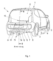
- a passenger vehicle 1 Illustrated by a passenger vehicle 1 is a structure 4 supported by wheels 2 and 3, which comprises in a tail 5 a glass pane 8 brought close to a bumper 7 with a lower boundary edge 6 extending in the vehicle transverse direction A-A.
- the glass sheet 8 extends over a substantial width of the passenger car 1 and is provided with a windshield wiper arm 9, the pivot axis 10 is located on a central longitudinal plane B-B of said passenger car.
- a towing device 11 Adjacent to the lower edge of the bumper 7 extends in the vehicle transverse direction AA a towing device 11, which forms a pipe section 12 formed as a cross member 13, for example.
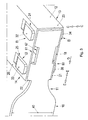
- the cross member 13 is provided at end portions 14 and 15 with longitudinal members 16 and 17.
- the metal section made of metal-lightweight metal, steel composite material or the like. 12 comprises a quadrangular cross-section, which is designed in the embodiment as a rectangular cross section 18.
- a connecting system 19 is mounted on the cross member 13, which is connected to a support device eg for bicycles or a trailer - the latter are not shown - can be coupled.
- the cross member 13 can be seen straight or curved in its longitudinal direction.
- the cross section 18 has longer, -in vehicle height direction CC - Figure 3 considered upper and lower horizontal walls 20 and 21 and -in the direction of travel D viewed shorter front and rear contributing to the formation of the cross section 18 upright or vertical walls 22 and 23.
- the upper and lower walls 20 and 21 of the cross section 18th have at the end portions 14 and 15 receptacles 24 and 25 and 26 and 27 or 28 and 29 and 30 and 31.
- each side rail for example, the side rail 16, is made of high-strength sheet such as metal, plastic, composite material or the like. Made and fixed to not shown frame portions of the structure 4.
- a longer cross-sectional side 40 of the sword-type longitudinal member 16 is substantially perpendicular and the bending elements 32 and 33 and 34 and 35 are formed by bends 41 and 42 and 43 and 44 of the longitudinal member 16, said bending elements 32 and 33 and 34 and 35 from a piece are made with the longitudinal member 16 and transversely to the vehicle longitudinal direction EE - Fig. 3 - lost. It is also conceivable, however, to manufacture the longitudinal member 16 and the bending elements 32 and 33 as well as 34 and 35 separately from one another and then to assemble them. For holding the longitudinal member 16 of this is provided with through holes 45 and 46 for fastening screws, not shown.
- the cross member 13 includes between the horizontal walls 20 and 21 and upright walls 22 and 23 support walls 47, 48 and 49 - Fig. 3 -.
- the support walls 47, 48 and 49 together with the horizontal walls 20 and 21 and the upright walls 22 and 23 chambers 50, 51 and 52 and 53, 54 and 55th
- the receptacles 24 and 25 and 26 and 27 for the bending elements 32 and 33 or 35 and 34 in the upper and the lower wall 20, 21 of the cross section 18 for the associated bending elements 32 and 33 and 34 and 35 are each through a cutout 56th eg formed in the upper wall 20.
- This cutout 56 has a quadrangular shape, and a wall portion Wt of the cutout 56 is separated from the wall 20 only on three sides 58, 59 and 60.
- a fourth remote from a support end 61 of the cross member 13 side 62 of the cutout 56 is designed as a bending edge 63, via which a remaining wall portion Wt of the upper wall 20 is turned off as a ramp 64 in the interior 65 of the cross member 13. By means of this ramp 64, the corresponding bending element 32 is moved to a pre-position Vp.
- each end region, for example, 14 of the cross member 13 on the upper wall 20 and the lower wall 21 each have two in the vehicle longitudinal direction E-E spaced and aligned in the vehicle transverse direction
- A-A bending elements 32 and 33 and 34 and 35 are provided at each end region, for example, 14 of the cross member 13 on the upper wall 20 and the lower wall 21 each have two in the vehicle longitudinal direction E-E spaced and aligned in the vehicle transverse direction
- A-A bending elements 32 and 33 and 34 and 35 are provided at each end region, for example, 14 of the cross member 13 on the upper wall 20 and the lower wall 21 each have two in the vehicle longitudinal direction E-E spaced and aligned in the vehicle transverse direction
- A-A bending elements 32 and 33 and 34 and 35 are provided at each end region, for example, 14 of the cross member 13 on the upper wall 20 and the lower wall 21 each have two in the vehicle longitudinal direction E-E spaced and aligned in the vehicle transverse direction
- A-A bending elements 32 and 33 and 34 and 35 are
- Each tongue-like bending element for example the bending element 32, is provided with a flat cross section and, viewed in its length L, has a guide section adjacent to the stop 67 Fa, which cooperates with upright wall portions WbI and WbII in the chamber 50 of the cross member 18. At the guide portion Fa connects to a bending section Ba, the insertion into the receptacle 24 and prepositioned during assembly by means of the ramp 64.
- the connection system 19 comprises a receiving element 70 which is fastened to the crossbeam 13 in the central longitudinal plane B-B and which surrounds the crossbeam 13 with an eg U-shaped cross-section and comprises e.g. is attached by gluing.
- a ball neck 71 is connectable.
- a dovetail joint 74 is effective between a upright support pin 72 of the ball neck 71 and a leg 73 of the receiving element 70.
Landscapes
- Engineering & Computer Science (AREA)
- Transportation (AREA)
- Mechanical Engineering (AREA)
- Body Structure For Vehicles (AREA)
Priority Applications (1)
| Application Number | Priority Date | Filing Date | Title |
|---|---|---|---|
| PL12008519T PL2607111T3 (pl) | 2011-12-24 | 2012-12-21 | Układ nośny dla sprzęgu doczepnego pojazdu mechanicznego |
Applications Claiming Priority (1)
| Application Number | Priority Date | Filing Date | Title |
|---|---|---|---|
| DE102011122468A DE102011122468B4 (de) | 2011-12-24 | 2011-12-24 | Trägersystem für eine Anhängekupplung eines Kraftfahrzeugs |
Publications (2)
| Publication Number | Publication Date |
|---|---|
| EP2607111A1 true EP2607111A1 (fr) | 2013-06-26 |
| EP2607111B1 EP2607111B1 (fr) | 2015-10-21 |
Family
ID=47594215
Family Applications (1)
| Application Number | Title | Priority Date | Filing Date |
|---|---|---|---|
| EP12008519.6A Active EP2607111B1 (fr) | 2011-12-24 | 2012-12-21 | Système de support pour une remorque de véhicule automobile |
Country Status (4)
| Country | Link |
|---|---|
| EP (1) | EP2607111B1 (fr) |
| DE (1) | DE102011122468B4 (fr) |
| HU (1) | HUE027506T2 (fr) |
| PL (1) | PL2607111T3 (fr) |
Cited By (4)
| Publication number | Priority date | Publication date | Assignee | Title |
|---|---|---|---|---|
| EP3150409A1 (fr) * | 2015-09-30 | 2017-04-05 | WESTFALIA - Automotive GmbH | Système de support pour un attelage ou un support de charge |
| WO2018162026A1 (fr) * | 2017-03-06 | 2018-09-13 | Brink Towing Systems B.V. | Barre de remorquage et procédé de fabrication d'une barre de remorquage |
| JP2021104783A (ja) * | 2019-12-27 | 2021-07-26 | マツダ株式会社 | 車両の後部車体構造 |
| US11179983B2 (en) * | 2018-07-12 | 2021-11-23 | Morgan Olson Corporation | Trailer hitch mounting assembly |
Families Citing this family (5)
| Publication number | Priority date | Publication date | Assignee | Title |
|---|---|---|---|---|
| DE102013008323A1 (de) | 2013-05-08 | 2014-11-13 | Westfalia-Automotive Gmbh | Trägeranordnung für eine Anhängekupplung oder einen Lastenträger mit Steckzapfen |
| DE102013008326B4 (de) | 2013-05-08 | 2023-08-31 | Westfalia-Automotive Gmbh | Trägeranordnung für eine Anhängekupplung oder einen Lastenträger mit einem Profilkörper und Verfahren zur Herstellung einer Trägeranordnung |
| DE102013008327A1 (de) | 2013-05-08 | 2014-11-13 | Westfalia-Automotive Gmbh | Trägeranordnung für eine Anhängekupplung oder einen Lastenträger mit Biegelaschen |
| DE102013008325A1 (de) | 2013-05-08 | 2014-11-13 | Westfalia-Automotive Gmbh | Trägeranordnung für eine Anhängekupplung oder einen Lastenträger mit Hakenkonturen |
| DE102018216816B4 (de) * | 2018-09-28 | 2021-02-25 | Audi Ag | Vorrichtung zur Verhinderung des Durchstoßens einer Bodenstruktur eines Kraftfahrzeugs und Kraftfahrzeug |
Citations (7)
| Publication number | Priority date | Publication date | Assignee | Title |
|---|---|---|---|---|
| DE9006077U1 (de) | 1990-05-12 | 1990-08-16 | AL-KO Kober AG, 8871 Kötz | Wechselbare Anhängerkupplung für Zugfahrzeuge |
| US20040239076A1 (en) * | 2002-12-11 | 2004-12-02 | Mccoy Richard W. | Dual accessory port adaptor |
| US20050179232A1 (en) * | 2004-02-13 | 2005-08-18 | Martinrea International Inc. | Hitch assembly |
| US20050236809A1 (en) | 2004-04-27 | 2005-10-27 | Aisin Seiki Kabushiki Kaisha | Towing hook mounting structure for vehicle |
| EP2095978A1 (fr) * | 2008-02-28 | 2009-09-02 | Scambia Industrial Developments Aktiengesellschaft | Attelage |
| DE202009006345U1 (de) | 2009-05-04 | 2010-09-23 | Al-Ko Kober Ag | Trägeranordnung |
| US20110109063A1 (en) | 2009-10-30 | 2011-05-12 | Fudala Chris J | Towing hitch cross-member assembly with self-locating tabs |
-
2011
- 2011-12-24 DE DE102011122468A patent/DE102011122468B4/de active Active
-
2012
- 2012-12-21 EP EP12008519.6A patent/EP2607111B1/fr active Active
- 2012-12-21 HU HUE12008519A patent/HUE027506T2/hu unknown
- 2012-12-21 PL PL12008519T patent/PL2607111T3/pl unknown
Patent Citations (7)
| Publication number | Priority date | Publication date | Assignee | Title |
|---|---|---|---|---|
| DE9006077U1 (de) | 1990-05-12 | 1990-08-16 | AL-KO Kober AG, 8871 Kötz | Wechselbare Anhängerkupplung für Zugfahrzeuge |
| US20040239076A1 (en) * | 2002-12-11 | 2004-12-02 | Mccoy Richard W. | Dual accessory port adaptor |
| US20050179232A1 (en) * | 2004-02-13 | 2005-08-18 | Martinrea International Inc. | Hitch assembly |
| US20050236809A1 (en) | 2004-04-27 | 2005-10-27 | Aisin Seiki Kabushiki Kaisha | Towing hook mounting structure for vehicle |
| EP2095978A1 (fr) * | 2008-02-28 | 2009-09-02 | Scambia Industrial Developments Aktiengesellschaft | Attelage |
| DE202009006345U1 (de) | 2009-05-04 | 2010-09-23 | Al-Ko Kober Ag | Trägeranordnung |
| US20110109063A1 (en) | 2009-10-30 | 2011-05-12 | Fudala Chris J | Towing hitch cross-member assembly with self-locating tabs |
Cited By (5)
| Publication number | Priority date | Publication date | Assignee | Title |
|---|---|---|---|---|
| EP3150409A1 (fr) * | 2015-09-30 | 2017-04-05 | WESTFALIA - Automotive GmbH | Système de support pour un attelage ou un support de charge |
| WO2018162026A1 (fr) * | 2017-03-06 | 2018-09-13 | Brink Towing Systems B.V. | Barre de remorquage et procédé de fabrication d'une barre de remorquage |
| US11179983B2 (en) * | 2018-07-12 | 2021-11-23 | Morgan Olson Corporation | Trailer hitch mounting assembly |
| US20220072920A1 (en) * | 2018-07-12 | 2022-03-10 | Morgan Olson Corporation | Trailer Hitch Mounting Assembly |
| JP2021104783A (ja) * | 2019-12-27 | 2021-07-26 | マツダ株式会社 | 車両の後部車体構造 |
Also Published As
| Publication number | Publication date |
|---|---|
| EP2607111B1 (fr) | 2015-10-21 |
| DE102011122468B4 (de) | 2013-08-08 |
| PL2607111T3 (pl) | 2016-04-29 |
| HUE027506T2 (hu) | 2016-10-28 |
| DE102011122468A1 (de) | 2013-06-27 |
Similar Documents
| Publication | Publication Date | Title |
|---|---|---|
| EP2607111B1 (fr) | Système de support pour une remorque de véhicule automobile | |
| DE102008036335A1 (de) | Versteifungsvorrichtung | |
| DE102011005564A1 (de) | Fahrzeug-Achsträger | |
| DE202009006345U1 (de) | Trägeranordnung | |
| DE102009050495A1 (de) | Hilfsrahmen | |
| DE102008032543A1 (de) | Crashbox für ein Kraftfahrzeug | |
| DE202008009572U1 (de) | Fahrzeuganhänger | |
| DE102022107029A1 (de) | Anhängerkupplungsbaugruppe | |
| DE202009011491U1 (de) | Fahrgestell | |
| DE102006009189B3 (de) | Befestigungsanordnung von Außenanbauteilen an einem Tragrahmen eines Lastkraftwagens | |
| DE102019106226A1 (de) | Kraftfahrzeug mit einem Achsträger und einer elektrischen Speichereinheit | |
| DE102012213019B4 (de) | Zugkopfteil | |
| DE202012102786U1 (de) | Trageinrichtung | |
| DE102012022613B4 (de) | Anhängesystem für ein Kraftfahrzeug | |
| EP2607112B1 (fr) | Dispositif de remorque pour un véhicule | |
| DE102010007379A1 (de) | Montageverfahren und Montagestation für eine Fahrzeugkarosserie, insbesondere für Kleinserien | |
| DE102012022614B3 (de) | Anhängesystem für ein Kraftfahrzeug | |
| EP3106327B1 (fr) | Attelage et parties de bride | |
| EP2955087A2 (fr) | Remorque de vehicule abaissable | |
| EP2607113B1 (fr) | Poutre creuse pour un système de remorque d'un véhicule automobile | |
| DE102005034552B4 (de) | Stützwinde | |
| DE10140921A1 (de) | Fahrgestell für ein Nutzfahrzeug, Bausatz und Verfahren zur Spurverbreiterung und Radstandsverlängerung des Fahrgestells | |
| DE102010019149A1 (de) | Vorderwagen eines Fahrzeugs | |
| EP3287347B2 (fr) | Entraînement d'assistance pour une remorque et remorque | |
| DE102005041216A1 (de) | Befestigungsanordnung von Außenbeplankungsteilen eines Kraftwagens |
Legal Events
| Date | Code | Title | Description |
|---|---|---|---|
| AK | Designated contracting states |
Kind code of ref document: A1 Designated state(s): AL AT BE BG CH CY CZ DE DK EE ES FI FR GB GR HR HU IE IS IT LI LT LU LV MC MK MT NL NO PL PT RO RS SE SI SK SM TR |
|
| AX | Request for extension of the european patent |
Extension state: BA ME |
|
| PUAI | Public reference made under article 153(3) epc to a published international application that has entered the european phase |
Free format text: ORIGINAL CODE: 0009012 |
|
| 17P | Request for examination filed |
Effective date: 20131206 |
|
| RBV | Designated contracting states (corrected) |
Designated state(s): AL AT BE BG CH CY CZ DE DK EE ES FI FR GB GR HR HU IE IS IT LI LT LU LV MC MK MT NL NO PL PT RO RS SE SI SK SM TR |
|
| GRAP | Despatch of communication of intention to grant a patent |
Free format text: ORIGINAL CODE: EPIDOSNIGR1 |
|
| INTG | Intention to grant announced |
Effective date: 20150611 |
|
| GRAS | Grant fee paid |
Free format text: ORIGINAL CODE: EPIDOSNIGR3 |
|
| GRAA | (expected) grant |
Free format text: ORIGINAL CODE: 0009210 |
|
| AK | Designated contracting states |
Kind code of ref document: B1 Designated state(s): AL AT BE BG CH CY CZ DE DK EE ES FI FR GB GR HR HU IE IS IT LI LT LU LV MC MK MT NL NO PL PT RO RS SE SI SK SM TR |
|
| REG | Reference to a national code |
Ref country code: GB Ref legal event code: FG4D Free format text: NOT ENGLISH Ref country code: NL Ref legal event code: MP Effective date: 20151021 |
|
| REG | Reference to a national code |
Ref country code: CH Ref legal event code: EP |
|
| REG | Reference to a national code |
Ref country code: AT Ref legal event code: REF Ref document number: 756358 Country of ref document: AT Kind code of ref document: T Effective date: 20151115 |
|
| REG | Reference to a national code |
Ref country code: IE Ref legal event code: FG4D Free format text: LANGUAGE OF EP DOCUMENT: GERMAN |
|
| REG | Reference to a national code |
Ref country code: DE Ref legal event code: R096 Ref document number: 502012004994 Country of ref document: DE |
|
| REG | Reference to a national code |
Ref country code: FR Ref legal event code: PLFP Year of fee payment: 4 |
|
| REG | Reference to a national code |
Ref country code: LT Ref legal event code: MG4D |
|
| PG25 | Lapsed in a contracting state [announced via postgrant information from national office to epo] |
Ref country code: NL Free format text: LAPSE BECAUSE OF FAILURE TO SUBMIT A TRANSLATION OF THE DESCRIPTION OR TO PAY THE FEE WITHIN THE PRESCRIBED TIME-LIMIT Effective date: 20151021 Ref country code: NO Free format text: LAPSE BECAUSE OF FAILURE TO SUBMIT A TRANSLATION OF THE DESCRIPTION OR TO PAY THE FEE WITHIN THE PRESCRIBED TIME-LIMIT Effective date: 20160121 Ref country code: IT Free format text: LAPSE BECAUSE OF FAILURE TO SUBMIT A TRANSLATION OF THE DESCRIPTION OR TO PAY THE FEE WITHIN THE PRESCRIBED TIME-LIMIT Effective date: 20151021 Ref country code: HR Free format text: LAPSE BECAUSE OF FAILURE TO SUBMIT A TRANSLATION OF THE DESCRIPTION OR TO PAY THE FEE WITHIN THE PRESCRIBED TIME-LIMIT Effective date: 20151021 Ref country code: ES Free format text: LAPSE BECAUSE OF FAILURE TO SUBMIT A TRANSLATION OF THE DESCRIPTION OR TO PAY THE FEE WITHIN THE PRESCRIBED TIME-LIMIT Effective date: 20151021 Ref country code: LT Free format text: LAPSE BECAUSE OF FAILURE TO SUBMIT A TRANSLATION OF THE DESCRIPTION OR TO PAY THE FEE WITHIN THE PRESCRIBED TIME-LIMIT Effective date: 20151021 Ref country code: IS Free format text: LAPSE BECAUSE OF FAILURE TO SUBMIT A TRANSLATION OF THE DESCRIPTION OR TO PAY THE FEE WITHIN THE PRESCRIBED TIME-LIMIT Effective date: 20160221 |
|
| PG25 | Lapsed in a contracting state [announced via postgrant information from national office to epo] |
Ref country code: GR Free format text: LAPSE BECAUSE OF FAILURE TO SUBMIT A TRANSLATION OF THE DESCRIPTION OR TO PAY THE FEE WITHIN THE PRESCRIBED TIME-LIMIT Effective date: 20160122 Ref country code: FI Free format text: LAPSE BECAUSE OF FAILURE TO SUBMIT A TRANSLATION OF THE DESCRIPTION OR TO PAY THE FEE WITHIN THE PRESCRIBED TIME-LIMIT Effective date: 20151021 Ref country code: PT Free format text: LAPSE BECAUSE OF FAILURE TO SUBMIT A TRANSLATION OF THE DESCRIPTION OR TO PAY THE FEE WITHIN THE PRESCRIBED TIME-LIMIT Effective date: 20160222 Ref country code: LV Free format text: LAPSE BECAUSE OF FAILURE TO SUBMIT A TRANSLATION OF THE DESCRIPTION OR TO PAY THE FEE WITHIN THE PRESCRIBED TIME-LIMIT Effective date: 20151021 Ref country code: RS Free format text: LAPSE BECAUSE OF FAILURE TO SUBMIT A TRANSLATION OF THE DESCRIPTION OR TO PAY THE FEE WITHIN THE PRESCRIBED TIME-LIMIT Effective date: 20151021 Ref country code: BE Free format text: LAPSE BECAUSE OF NON-PAYMENT OF DUE FEES Effective date: 20151231 Ref country code: SE Free format text: LAPSE BECAUSE OF FAILURE TO SUBMIT A TRANSLATION OF THE DESCRIPTION OR TO PAY THE FEE WITHIN THE PRESCRIBED TIME-LIMIT Effective date: 20151021 |
|
| REG | Reference to a national code |
Ref country code: DE Ref legal event code: R097 Ref document number: 502012004994 Country of ref document: DE |
|
| PG25 | Lapsed in a contracting state [announced via postgrant information from national office to epo] |
Ref country code: MC Free format text: LAPSE BECAUSE OF FAILURE TO SUBMIT A TRANSLATION OF THE DESCRIPTION OR TO PAY THE FEE WITHIN THE PRESCRIBED TIME-LIMIT Effective date: 20151021 Ref country code: LU Free format text: LAPSE BECAUSE OF FAILURE TO SUBMIT A TRANSLATION OF THE DESCRIPTION OR TO PAY THE FEE WITHIN THE PRESCRIBED TIME-LIMIT Effective date: 20151221 |
|
| REG | Reference to a national code |
Ref country code: CH Ref legal event code: PL |
|
| PLBE | No opposition filed within time limit |
Free format text: ORIGINAL CODE: 0009261 |
|
| STAA | Information on the status of an ep patent application or granted ep patent |
Free format text: STATUS: NO OPPOSITION FILED WITHIN TIME LIMIT |
|
| PG25 | Lapsed in a contracting state [announced via postgrant information from national office to epo] |
Ref country code: EE Free format text: LAPSE BECAUSE OF FAILURE TO SUBMIT A TRANSLATION OF THE DESCRIPTION OR TO PAY THE FEE WITHIN THE PRESCRIBED TIME-LIMIT Effective date: 20151021 Ref country code: RO Free format text: LAPSE BECAUSE OF FAILURE TO SUBMIT A TRANSLATION OF THE DESCRIPTION OR TO PAY THE FEE WITHIN THE PRESCRIBED TIME-LIMIT Effective date: 20151021 Ref country code: SK Free format text: LAPSE BECAUSE OF FAILURE TO SUBMIT A TRANSLATION OF THE DESCRIPTION OR TO PAY THE FEE WITHIN THE PRESCRIBED TIME-LIMIT Effective date: 20151021 Ref country code: SM Free format text: LAPSE BECAUSE OF FAILURE TO SUBMIT A TRANSLATION OF THE DESCRIPTION OR TO PAY THE FEE WITHIN THE PRESCRIBED TIME-LIMIT Effective date: 20151021 Ref country code: DK Free format text: LAPSE BECAUSE OF FAILURE TO SUBMIT A TRANSLATION OF THE DESCRIPTION OR TO PAY THE FEE WITHIN THE PRESCRIBED TIME-LIMIT Effective date: 20151021 |
|
| REG | Reference to a national code |
Ref country code: IE Ref legal event code: MM4A |
|
| 26N | No opposition filed |
Effective date: 20160722 |
|
| REG | Reference to a national code |
Ref country code: HU Ref legal event code: AG4A Ref document number: E027506 Country of ref document: HU |
|
| PG25 | Lapsed in a contracting state [announced via postgrant information from national office to epo] |
Ref country code: IE Free format text: LAPSE BECAUSE OF NON-PAYMENT OF DUE FEES Effective date: 20151221 Ref country code: LI Free format text: LAPSE BECAUSE OF NON-PAYMENT OF DUE FEES Effective date: 20151231 Ref country code: CH Free format text: LAPSE BECAUSE OF NON-PAYMENT OF DUE FEES Effective date: 20151231 |
|
| REG | Reference to a national code |
Ref country code: FR Ref legal event code: PLFP Year of fee payment: 5 |
|
| PG25 | Lapsed in a contracting state [announced via postgrant information from national office to epo] |
Ref country code: SI Free format text: LAPSE BECAUSE OF FAILURE TO SUBMIT A TRANSLATION OF THE DESCRIPTION OR TO PAY THE FEE WITHIN THE PRESCRIBED TIME-LIMIT Effective date: 20151021 |
|
| PG25 | Lapsed in a contracting state [announced via postgrant information from national office to epo] |
Ref country code: BG Free format text: LAPSE BECAUSE OF FAILURE TO SUBMIT A TRANSLATION OF THE DESCRIPTION OR TO PAY THE FEE WITHIN THE PRESCRIBED TIME-LIMIT Effective date: 20151021 |
|
| PG25 | Lapsed in a contracting state [announced via postgrant information from national office to epo] |
Ref country code: CY Free format text: LAPSE BECAUSE OF FAILURE TO SUBMIT A TRANSLATION OF THE DESCRIPTION OR TO PAY THE FEE WITHIN THE PRESCRIBED TIME-LIMIT Effective date: 20151021 |
|
| GBPC | Gb: european patent ceased through non-payment of renewal fee |
Effective date: 20161221 |
|
| PG25 | Lapsed in a contracting state [announced via postgrant information from national office to epo] |
Ref country code: MT Free format text: LAPSE BECAUSE OF FAILURE TO SUBMIT A TRANSLATION OF THE DESCRIPTION OR TO PAY THE FEE WITHIN THE PRESCRIBED TIME-LIMIT Effective date: 20151021 |
|
| REG | Reference to a national code |
Ref country code: FR Ref legal event code: PLFP Year of fee payment: 6 |
|
| PG25 | Lapsed in a contracting state [announced via postgrant information from national office to epo] |
Ref country code: GB Free format text: LAPSE BECAUSE OF NON-PAYMENT OF DUE FEES Effective date: 20161221 |
|
| PG25 | Lapsed in a contracting state [announced via postgrant information from national office to epo] |
Ref country code: TR Free format text: LAPSE BECAUSE OF FAILURE TO SUBMIT A TRANSLATION OF THE DESCRIPTION OR TO PAY THE FEE WITHIN THE PRESCRIBED TIME-LIMIT Effective date: 20151021 Ref country code: MK Free format text: LAPSE BECAUSE OF FAILURE TO SUBMIT A TRANSLATION OF THE DESCRIPTION OR TO PAY THE FEE WITHIN THE PRESCRIBED TIME-LIMIT Effective date: 20151021 |
|
| PG25 | Lapsed in a contracting state [announced via postgrant information from national office to epo] |
Ref country code: AL Free format text: LAPSE BECAUSE OF FAILURE TO SUBMIT A TRANSLATION OF THE DESCRIPTION OR TO PAY THE FEE WITHIN THE PRESCRIBED TIME-LIMIT Effective date: 20151021 |
|
| REG | Reference to a national code |
Ref country code: AT Ref legal event code: MM01 Ref document number: 756358 Country of ref document: AT Kind code of ref document: T Effective date: 20171221 |
|
| PG25 | Lapsed in a contracting state [announced via postgrant information from national office to epo] |
Ref country code: AT Free format text: LAPSE BECAUSE OF NON-PAYMENT OF DUE FEES Effective date: 20171221 |
|
| PGFP | Annual fee paid to national office [announced via postgrant information from national office to epo] |
Ref country code: CZ Payment date: 20211220 Year of fee payment: 10 Ref country code: FR Payment date: 20211110 Year of fee payment: 10 |
|
| PGFP | Annual fee paid to national office [announced via postgrant information from national office to epo] |
Ref country code: HU Payment date: 20211218 Year of fee payment: 10 |
|
| PGFP | Annual fee paid to national office [announced via postgrant information from national office to epo] |
Ref country code: PL Payment date: 20211209 Year of fee payment: 10 |
|
| PG25 | Lapsed in a contracting state [announced via postgrant information from national office to epo] |
Ref country code: CZ Free format text: LAPSE BECAUSE OF NON-PAYMENT OF DUE FEES Effective date: 20221221 |
|
| PG25 | Lapsed in a contracting state [announced via postgrant information from national office to epo] |
Ref country code: HU Free format text: LAPSE BECAUSE OF NON-PAYMENT OF DUE FEES Effective date: 20221222 Ref country code: FR Free format text: LAPSE BECAUSE OF NON-PAYMENT OF DUE FEES Effective date: 20221231 |
|
| PG25 | Lapsed in a contracting state [announced via postgrant information from national office to epo] |
Ref country code: PL Free format text: LAPSE BECAUSE OF NON-PAYMENT OF DUE FEES Effective date: 20221221 |
|
| PGFP | Annual fee paid to national office [announced via postgrant information from national office to epo] |
Ref country code: DE Payment date: 20251229 Year of fee payment: 14 |