EP2607162B1 - Procédé de fabrication et/ou de transformation d'un dispositif de fixation destiné à fixer des marchandises de chargement dans une soute - Google Patents
Procédé de fabrication et/ou de transformation d'un dispositif de fixation destiné à fixer des marchandises de chargement dans une soute Download PDFInfo
- Publication number
- EP2607162B1 EP2607162B1 EP12198100.5A EP12198100A EP2607162B1 EP 2607162 B1 EP2607162 B1 EP 2607162B1 EP 12198100 A EP12198100 A EP 12198100A EP 2607162 B1 EP2607162 B1 EP 2607162B1
- Authority
- EP
- European Patent Office
- Prior art keywords
- rail
- retainer
- base element
- fastening device
- base
- Prior art date
- Legal status (The legal status is an assumption and is not a legal conclusion. Google has not performed a legal analysis and makes no representation as to the accuracy of the status listed.)
- Active
Links
Images



Classifications
-
- B—PERFORMING OPERATIONS; TRANSPORTING
- B60—VEHICLES IN GENERAL
- B60P—VEHICLES ADAPTED FOR LOAD TRANSPORTATION OR TO TRANSPORT, TO CARRY, OR TO COMPRISE SPECIAL LOADS OR OBJECTS
- B60P7/00—Securing or covering of load on vehicles
- B60P7/06—Securing of load
- B60P7/08—Securing to the vehicle floor or sides
- B60P7/0807—Attachment points
Definitions
- the invention relates to a method for producing and / or converting a fastening device for fixing cargo in a cargo hold according to the preamble of claim 1, as well as a kit for carrying out this method and corresponding fastening devices.
- a similar slider which is guided along a rail and in which a bolt is integrated for retraction into a rail recess, which is held under the pressure of a spring in latching position, is for example from DE 203 06 549 U1 known.
- a device for temporary connection of an object with a holding or rail profile in which approximately parallel to the longitudinal axis of an undercut longitudinal groove which is provided with axially spaced holes, between each of which a pair of the longitudinal groove laterally limiting and whose undercut overlapping groove edges is arranged. It should be lockable and releasably insertable in the longitudinal groove, wherein the serving as an intermediate element insert is formed insertable into adjacent holes of the rail profile that a plate-like support surface dominates the surface of the rail profile and on the other hand, at least one Kragorgan of the insert element, the lower surface of the Nutkanten forming ribs of the rail profile engages under.
- the object of the present invention is to provide a method, a kit for carrying out this method and corresponding fastening devices, which are extremely versatile and with a minimum of individual parts a maximum of functions and Products, which can significantly reduce costs.
- the basic idea of the present invention is to provide fastening devices of the above mentioned type. To create a kind of collection that is composed of as few individual elements as possible, but can accommodate different requirements. Depending on these different requirements, the fastening devices can be assembled and made available to the customer. The requirements are based on the rails themselves. This means that the base elements must be adapted to these rails. In today's fastening technology, especially in the cargo holds of vehicles, for example so-called airline rails or keyhole rails are used. Depending on their design, the base element is formed.
- a retainer which serves to fix the base element in an airline rail, has a different configuration than a retainer for, for example, a keyhole rail.
- the retainer consists of an always constant body in which only a different locking element is used, depending on whether the attachment device is suitable for an airline rail or for a keyhole rail.
- the retainer serves to fix the base element in relation to the rail. For this reason, the retainer is usually formed vertically displaceable relative to the base member. In lock position, he drives with corresponding Riegelhesschen in recesses of the rail, however, it should then also be designed to be liftable vertically again, so that this locking position can be solved.
- the whole thing is preferably done against the force of an energy storage device, for example against the force of a coil spring.
- fasteners There are fasteners on which, for example, a lashing strap is to be determined.
- the connecting element is designed as a bracket.
- Other fasteners should have a bolt to be inserted into a blind hole in the load.
- Other connecting elements are bar shoe-like, formed for example for locking bar.
- all connecting elements have in common that they are preferably connected by a pin to the base element.
- the connecting element engages between two tabs of the base element, wherein a passage of the connecting element congruent with one opening in the tab. Through these two openings and the passage in the connecting element, a pin can be inserted.
- the pin is designed as a dowel pin.
- he has a longitudinal slot, whereby a diameter of the pin can be reduced. If the pin then sits in the locked position, it expands again, which avoids clattering of the connecting element relative to the base element.
- This may be, for example, a company logo of a particular company, in particular the company using the fastening device.
- the pin is designed as a quick release.
- the pin may be formed as an Allen and have a certain cross section, which cooperates with a matching cross section of the passages, so that a tension takes place.
- Many possibilities are conceivable here and should be covered by the present invention.
- kits of the various o.g. Elements for carrying out the method has a plurality of different base elements and retainers, which are provided for different rails, as well as a plurality of different connecting elements for different loads.
- the inventive concept also includes a fastening device that has been produced by the method according to the invention.
- connection element is connected to the base element in the manner described above, ie in which the base element has at least two, preferably four congruent openings and the connecting element between the at least two, preferably four openings engages and has a passage connecting the openings, wherein a pin is inserted through the openings and the passage.
- the connecting element has a gimbal-like movable head.
- the connecting element consists of a bridge element, from which a rotary piece rises, which is rotatable relative to the bridge element. This turntable then sits in turn a fork-shaped hat, which is rotatable about a horizontal axis relative to the rotating piece.
- An attachment device P1 for securing cargo in a cargo compartment has a base element 1 for insertion into a cargo compartment
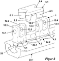
- FIG. 2 shown rail 23.1 and a retainer 2 for locking the base member 1 on the rail and a connecting element 3 to the load.
- the base member 1 is intended for insertion into a so-called airline rail 23.1, as this example in the DE 100 36 553 A1 is described.
- This airline rail is characterized by opposing wave-shaped groove edges 24.1 and 24.2, which form insertion openings 25 for clamping feet 4.1, 4.2 and 4.3, wherein the base member 1 can be moved along the rail groove and thereby reach the clamping feet 4.1 to 4.3 under areas between the insertion openings , whereby the base member 1 is set in the airline rail.
- This position is then secured by a locking element 5.1, which in turn has latching feet 6.1 to 6.4, which retract into adjacent insertion opening of the airline rail. This is done under the pressure of a coil spring 7.
- the bolt feet 6.1-6.4 are at least partially adapted to the contours of the insert opening and tapered downwards formed, whereby the entire fastener P1 is set fairly rattle on the rail 23.
- the locking element 5.1 is inserted into a main body 8 of the retainer 2 and the entire retainer 2 together with the locking element 5.1 vertically along the base member 1 feasible.
- a guide element e.g. a pin to enforce a corresponding guide opening in the locking element 5.1.
- the coil spring 7 presses on the one hand on the locking element 5.1, on the other hand it is supported against an abutment 11, which is fixed together with the connecting element 3 on the base element 1.
- the connecting element 3 or a bow-shaped body 18 has in its end regions in each case a passage 14.1 and 14.2, which are arranged in the position of use between two tabs 12.1, 12.2 and 12.3, 12.4 and with the openings 13.1, 13.2 and 13.3, 13.4 congruent.
- Secured is the connecting element 3 by means of pins 15.1 and 15.2, which are inserted through the opening 13.1, the passage 14.1 and the opening 13.2 and an opening 13.4, 14.2, and 13.3.
- These pins are designed as dowel pins.
- they have a longitudinal slot, not shown in detail, whereby 15.1 and 15.2, the diameter can be reduced during insertion of the pins, but then spread in the position of use and so brace in the openings or passages.
- pins 15.1 and 15.2 can end whilrtig a label 17.1 and 17.2 be assigned, which is done for the sake of simplicity, that corresponding extensions are inserted at the markings 17.1 and 17.2 in the front opening of the sleeve-shaped pins 15.1 ,.15.2.
- a pin 9 of the abutment 11 can be used, whereby this also is set relative to the base elements 1. In FIG. 1 only one pin 9 is shown.
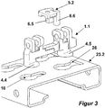
- FIG. 3 differs from the base element 1 in that it is suitable for a so-called keyhole rail 23.2.
- This keyhole rail is characterized by spaced keyhole-like recess 10, wherein the base member 1.1 has at least two clamping feet 4.4 and 4.5, which are inserted into the larger part of the keyhole recess 10. By axial displacement then engage these clamping feet 4.4 and 4.5 the narrower area of the keyhole.
- a corresponding locking element 5.2 for insertion into the main body 8 of the retainer 2 then also has only two locking feet 6.5 and 6.6, which engage in locking position in a correspondingly shaped part 26 of the keyhole, in which the clamping foot 4.5 has been used.
- a connecting element 3.1 is formed like a bridge and has an upstanding bolt 19, to which an arbitrary element for fixing the cargo may be arranged. It is also conceivable that a portion of the cargo has a blind hole into which the bolt 19 fits.
- the connecting element 3.2 has a gimbal head 20, which is rotatable relative to a bridge element 21 about a vertical axis A.
- a fork-shaped hat 22 is rotatable about a horizontal axis B.
- the operation of the present invention is as follows: For fastening devices P1 to P3 is a kit of base elements 1, 1.1, retainer 2 of base body 8 with different locking elements 5.1 and 5.2 and connecting elements 3, 3.1 and 3.2 are formed. Depending on the customer's request or requirements of the cargo holds, the basic elements 1, 1.1 are selected. If an airline rail 23.1 is present or provided in the hold, the base elements 1 are selected. If, on the other hand, a keyhole rail 23.2 is present or provided, the base element 1.1 is selected. The same applies to the locking element 5.1 or 5.2, in which case the main body 8 of the retainer is the same. This main body 8 has a latching or snap-in device, in which, depending on the requirement, the locking element 5.1 or the locking element 5.2 can be used.
- the retainer 2 with the respective locking element 5.1 or 5.2 is now inserted into the base element 1 or 1.1 and can be moved vertically relative to the base element 1 or 1.1.
- the coil spring 7 is inserted into the retainer 2 and is supported downward against the locking element 5.1 or 5.2 from.
- connection element 3 3.1 or 3.2 is selected.
- connecting element 3 and the addition of the abutment 11 is carried out to support against the coil spring 7.
- the other connecting elements 3.1 and 3.2 are supported against the coil spring 7 itself.
- the connecting elements 3, 3.1 and 3.2 are placed on the base element 1 or 1.1 such that they engage in each case between two lugs 12.1 and 12.2 or 12.3, 12.4 and congruate the corresponding passages 14.1 and 14.2 with the openings 13.1 to 13.4. Thereafter, the pins 15.1 and 15.2 are pushed through the openings and the passages and connect the connecting elements 3, 3.1, 3.2 with the base elements 1, 1.1. Finally, the labels 17.1 and 17.2 can then be inserted into the pins 15.1 and 15.2.
Landscapes
- Engineering & Computer Science (AREA)
- Transportation (AREA)
- Mechanical Engineering (AREA)
- Connection Of Plates (AREA)
- Fittings On The Vehicle Exterior For Carrying Loads, And Devices For Holding Or Mounting Articles (AREA)
- Clamps And Clips (AREA)
Claims (15)
- Procédé de fabrication et de transformation totalement variable d'un dispositif de fixation (P1, P2, P3) destiné à fixer des marchandises de chargement dans une soute, le dispositif de fixation étant fixé dans un rail (23.1, 23.2),
caractérisé par le fait que- au moins un élément de retenue central (2) qui reste maintenu dans toutes les variantes,- au moins un élément de base variable (1, 1.1) destiné à représenter la connexion au rail (23.1, 23.2), et- au moins un élément de connexion variable (3, 3.1, 3.2) destiné à permettre le cas d'arrimage des marchandises de chargement,sont assemblés selon différentes exigences. - Procédé selon la revendication 1, caractérisé par le fait que le moyen de fixation se compose de l'élément de base (1, 1.1) pouvant être placé dans le rail et pouvant être fixé dans et/ou à ce dernier, de l'élément de retenue (2) et de l'élément de connexion (3, 3.1, 3.2) aux marchandises de chargement, dans lequel est associé, à l'élément de base (1, 1.1), l'élément de retenue (2) pour verrouiller l'élément de base par rapport au rail.
- Procédé selon la revendication 2, caractérisé par le fait que parmi une pluralité d'éléments de base (1, 1.1) et l'élément de retenue (2) qui sont prévus pour différents rails (23.1, 23.2) sont choisis ceux qui sont destinés au rail désiré et ensuite connectés à l'élément de connexion (3, 3.1, 3.2) entrant en considération pour les marchandises de chargement.
- Procédé selon la revendication 2 ou 3, caractérisé par le fait que l'élément de retenue (2) consiste en un corps de base constant (8) dans lequel est placé un élément de verrouillage (5.1, 5.2) destiné au verrouillage de l'élément de base (1, 1.1) au rail.
- Procédé selon au moins l'une des revendications 2 à 4, caractérisé par le fait qu'entre l'élément de retenue (2) et l'élément de connexion (3, 3.1, 3.2) est placé un accumulateur d'énergie (7).
- Procédé selon au moins l'une des revendications 2 à 5, caractérisé par le fait que la connexion entre l'élément de connexion (3, 3.1, 3.2) et l'élément de base (1, 1.1) est réalisée à l'aide d'au moins une goupille (15.1, 15.2) ou autre.
- Procédé selon la revendication 6, caractérisé par le fait qu'à la goupille (15.1, 15.2) est associé un marquage (17.1, 17.2).
- Kit de construction pour la mise en oeuvre du procédé selon au moins l'une des revendications 1 à 7, caractérisé par une pluralité d'éléments de base (1, 1.1) différents et un élément de retenue (2) qui sont prévus pour des rails (23.1, 23.2) différents, ainsi qu'avec une pluralité d'éléments de connexion (3, 3.1, 3.2) différents pour différentes marchandises de chargement.
- Dispositif de fixation pour fixer des marchandises de chargement dans une soute, qui se compose d'un élément de base (1, 1.1) pouvant être placé dans un rail (23.2, 23.2) et pouvant être fixé dans et/ou à ce dernier et d'un élément de connexion (3, 3.1,3.2) aux marchandises de chargement, dans lequel est associé, à l'élément de base, un élément de retenue (2) pour verrouiller l'élément de base (1, 1.1) par rapport au rail, dans lequel l'élément de base (1, 1.1) présente au moins deux, de préférence quatre, ouvertures coïncidentes (13.1 à 13.4) et l'élément de connexion (3, 3.1, 3.2) s'engage entre les au moins deux, de préférence quatre, ouvertures (13.1 à 13.4) et présente un passage (14.1, 14.2) connectant les ouvertures, dans lequel une goupille (15.1, 15.2) est introduite à travers les ouvertures et le passage.
- Dispositif de fixation selon la revendication 9, caractérisé par le fait que de l'élément de base (1, 1.1) font saillie au moins deux, de préférence quatre, pattes (12.1 à 12.4) qui présentent les ouvertures (13.1 à 13.4) et entre lesquelles s'engage l'élément de connexion (3, 3.1, 3.2).
- Dispositif de fixation selon la revendication 9 ou 10, caractérisé par le fait que la goupille (15.1, 15.2) présente une fente longitudinale.
- Dispositif de fixation selon au moins l'une des revendications 9 à 11, caractérisé par le fait que la goupille (15.1, 15.2) est conçue comme un manchon et présente, à l'extrémité, une ouverture destinée à recevoir un marquage (17.1, 17.2).
- Dispositif de fixation pour fixer des marchandises de chargement dans une soute, qui se compose d'un élément de base (1, 1.1) pouvant être placé dans un rail et pouvant être fixé dans et/ou à ce dernier et d'un élément de connexion (3, 3.1,3.2) aux marchandises de chargement, dans lequel est associé, à l'élément de base, un élément de retenue (2) pour verrouiller l'élément de base (1, 1.1) par rapport au rail, dans lequel l'élément de retenue (2) présente un corps de base (8) dans lequel est placé un élément de verrouillage (5.1, 5.2).
- Dispositif de fixation selon la revendication 13, caractérisé par le fait que l'élément de retenue (2) peut être guidé verticalement le long de l'élément de base (1, 1.1).
- Dispositif de fixation pour fixer des marchandises de chargement dans une soute, qui se compose d'un élément de base (1, 1.1) pouvant être placé dans un rail (23.1, 23.2) et pouvant être fixé dans ou à ce dernier et d'un élément de connexion (3, 3.1, 3, 2) aux marchandises de chargement, dans lequel est associé, à l'élément de base, un élément de retenue (2) pour verrouiller l'élément de base par rapport au rail, dans lequel l'élément de connexion (3.2) présente une tête mobile (20) à la cardan.
Applications Claiming Priority (1)
| Application Number | Priority Date | Filing Date | Title |
|---|---|---|---|
| DE201110056722 DE102011056722A1 (de) | 2011-12-20 | 2011-12-20 | Verfahren zum Herstellen und/oder Umbauen einer Befestigungseinrichtung zum Festlegen von Ladegut in einem Frachtraum |
Publications (3)
| Publication Number | Publication Date |
|---|---|
| EP2607162A2 EP2607162A2 (fr) | 2013-06-26 |
| EP2607162A3 EP2607162A3 (fr) | 2018-02-21 |
| EP2607162B1 true EP2607162B1 (fr) | 2019-07-17 |
Family
ID=47504706
Family Applications (1)
| Application Number | Title | Priority Date | Filing Date |
|---|---|---|---|
| EP12198100.5A Active EP2607162B1 (fr) | 2011-12-20 | 2012-12-19 | Procédé de fabrication et/ou de transformation d'un dispositif de fixation destiné à fixer des marchandises de chargement dans une soute |
Country Status (2)
| Country | Link |
|---|---|
| EP (1) | EP2607162B1 (fr) |
| DE (1) | DE102011056722A1 (fr) |
Families Citing this family (5)
| Publication number | Priority date | Publication date | Assignee | Title |
|---|---|---|---|---|
| US9694734B2 (en) | 2015-11-25 | 2017-07-04 | Ford Global Technologies, Llc | Hinged cargo tie-down cleat |
| FR3065190B1 (fr) * | 2017-04-18 | 2021-02-26 | Pommier | Agencement d'anneau d'arrimage sur une structure de support tel que le bord de rive ou un plancher notamment de chargement d'un vehicule de transport |
| US11511678B2 (en) * | 2020-07-24 | 2022-11-29 | Polaris Industries Inc. | Article mounting system for a vehicle |
| DE102022114784B3 (de) | 2022-06-13 | 2023-07-20 | allsafe GmbH & Co.KG | Fitting und System aufweisend ein Fitting und eine Schiene |
| EP4520654A1 (fr) | 2023-09-11 | 2025-03-12 | AIRBUS HELICOPTERS DEUTSCHLAND GmbH | Appareil de connexion à une piste d'ancrage ou à un point d'ancrage dans un aéronef |
Family Cites Families (7)
| Publication number | Priority date | Publication date | Assignee | Title |
|---|---|---|---|---|
| DE10036551A1 (de) | 2000-03-03 | 2001-09-06 | Ancra Jungfalk Gmbh & Co Kg | Vorrichtung zum Verankern eines Sitzes an einem Fahrzeugboden |
| DE20306549U1 (de) | 2003-04-25 | 2003-07-17 | ANCRA Jungfalk GmbH & Co. KG, 78234 Engen | System zum Festlegen von Ladegut |
| DE202005000134U1 (de) | 2004-01-12 | 2005-06-23 | Allsafe Jungfalk Gmbh & Co. Kg | Vorrichtung zum Verbinden eines Gegenstandes mit einem Halteprofil |
| EP1794053B1 (fr) | 2004-09-28 | 2009-06-17 | allsafe Jungfalk GmbH & Co. KG | Dispositif de fixation d'un objet sur un rail |
| US7980798B1 (en) * | 2007-06-18 | 2011-07-19 | Adac Plastics, Inc. | Tie-down assembly |
| GB2466801A (en) * | 2009-01-07 | 2010-07-14 | Unwin C N Ltd | Anchorage system for fixing articles to vehicle floor rail |
| FR2943986A1 (fr) * | 2009-04-06 | 2010-10-08 | Antar Daouk | Dispositif d'accouplement avec faculte de deplacement longitudinal |
-
2011
- 2011-12-20 DE DE201110056722 patent/DE102011056722A1/de not_active Withdrawn
-
2012
- 2012-12-19 EP EP12198100.5A patent/EP2607162B1/fr active Active
Also Published As
| Publication number | Publication date |
|---|---|
| EP2607162A3 (fr) | 2018-02-21 |
| EP2607162A2 (fr) | 2013-06-26 |
| DE102011056722A1 (de) | 2013-06-20 |
Similar Documents
| Publication | Publication Date | Title |
|---|---|---|
| DE102011079334A1 (de) | Ladeschiene sowie Gleitstein für eine Ladeschiene | |
| EP2021244A1 (fr) | Dispositif de fixation d'un objet | |
| DE102013222651B4 (de) | Vorrichtung zum Sichern von Ladegut in einem Laderaum sowie Befestigungselement hierfür | |
| DE202005004134U1 (de) | Vorrichtung zum Festlegen eines Gegenstandes an einer Schiene | |
| EP2607162A2 (fr) | Procédé de fabrication et/ou de transformation d'un dispositif de fixation destiné à fixer des marchandises de chargement dans une soute | |
| DE102011009211A1 (de) | Klipsvorrichtung, Fahrzeugsitz und Kraftfahrzeug | |
| DE102010022845A1 (de) | Kantenschutzelement für die Anordnung ungerahmter PV-Module | |
| DE202013001846U1 (de) | Verdeckgestell für einen Planenaufbau sowie Schaftteil und Schlitten | |
| DE102007047755A1 (de) | Dachträgervorrichtung für ein Fahrzeug | |
| EP3773074B1 (fr) | Systeme de tiroir comprenant un rail sur lequel differents types de tiroirs peuvent etre installes | |
| DE102013003222B4 (de) | Verdeckgestell für einen Planenaufbau sowie Schaftteil und Schlitten | |
| EP2260742A1 (fr) | Système de meuble | |
| DE202015100194U1 (de) | Arretierungsplatte | |
| DE102016004768B4 (de) | Befestigungsvorrichtung, die primär für die sichere Installation von Komponenten in einem Fahrzeug vorgesehen ist | |
| DE102013102247A1 (de) | Verfarhen zum Verbinden einer Schiene mit einem Element eines Frachtraumes | |
| DE2848236A1 (de) | Halter fuer regale o.dgl. | |
| DE102007024658A1 (de) | Vorrichtung und Verfahren zum Befestigen, Verspannen oder Justieren zweier Bauteile zueinander | |
| DE20201327U1 (de) | Vorrichtung zum Verankern eines Sitzes an einem Fahrzeugboden | |
| EP4119754A1 (fr) | Agencement de plaque de fixation et agencement de cadre de porte | |
| EP1693252A1 (fr) | Mécanisme de montage | |
| DE10012771B4 (de) | Fahrzeugdach mit Dachöffnung und gleitverschiebbar geführter Himmelplatte mit Fangeinrichtung | |
| EP2803533A1 (fr) | Dispositif destiné à agencer une barre présentant un canal longitudinal sur un support | |
| DE202007006289U1 (de) | Lattenhalter für Unterbetten | |
| DE8322358U1 (de) | Aus kunststoff bestehende gartenbank | |
| DE102005046091A1 (de) | Kennzeichnungsvorrichtung für Fahrzeuge |
Legal Events
| Date | Code | Title | Description |
|---|---|---|---|
| AK | Designated contracting states |
Kind code of ref document: A2 Designated state(s): AL AT BE BG CH CY CZ DE DK EE ES FI FR GB GR HR HU IE IS IT LI LT LU LV MC MK MT NL NO PL PT RO RS SE SI SK SM TR |
|
| AX | Request for extension of the european patent |
Extension state: BA ME |
|
| PUAI | Public reference made under article 153(3) epc to a published international application that has entered the european phase |
Free format text: ORIGINAL CODE: 0009012 |
|
| RAP1 | Party data changed (applicant data changed or rights of an application transferred) |
Owner name: ALLSAFE GMBH & CO. KG |
|
| PUAL | Search report despatched |
Free format text: ORIGINAL CODE: 0009013 |
|
| AK | Designated contracting states |
Kind code of ref document: A3 Designated state(s): AL AT BE BG CH CY CZ DE DK EE ES FI FR GB GR HR HU IE IS IT LI LT LU LV MC MK MT NL NO PL PT RO RS SE SI SK SM TR |
|
| AX | Request for extension of the european patent |
Extension state: BA ME |
|
| RIC1 | Information provided on ipc code assigned before grant |
Ipc: B60P 7/08 20060101AFI20180118BHEP |
|
| STAA | Information on the status of an ep patent application or granted ep patent |
Free format text: STATUS: REQUEST FOR EXAMINATION WAS MADE |
|
| 17P | Request for examination filed |
Effective date: 20180718 |
|
| RBV | Designated contracting states (corrected) |
Designated state(s): AL AT BE BG CH CY CZ DE DK EE ES FI FR GB GR HR HU IE IS IT LI LT LU LV MC MK MT NL NO PL PT RO RS SE SI SK SM TR |
|
| GRAP | Despatch of communication of intention to grant a patent |
Free format text: ORIGINAL CODE: EPIDOSNIGR1 |
|
| STAA | Information on the status of an ep patent application or granted ep patent |
Free format text: STATUS: GRANT OF PATENT IS INTENDED |
|
| INTG | Intention to grant announced |
Effective date: 20190129 |
|
| GRAS | Grant fee paid |
Free format text: ORIGINAL CODE: EPIDOSNIGR3 |
|
| GRAA | (expected) grant |
Free format text: ORIGINAL CODE: 0009210 |
|
| STAA | Information on the status of an ep patent application or granted ep patent |
Free format text: STATUS: THE PATENT HAS BEEN GRANTED |
|
| AK | Designated contracting states |
Kind code of ref document: B1 Designated state(s): AL AT BE BG CH CY CZ DE DK EE ES FI FR GB GR HR HU IE IS IT LI LT LU LV MC MK MT NL NO PL PT RO RS SE SI SK SM TR |
|
| REG | Reference to a national code |
Ref country code: GB Ref legal event code: FG4D Free format text: NOT ENGLISH |
|
| REG | Reference to a national code |
Ref country code: CH Ref legal event code: EP |
|
| REG | Reference to a national code |
Ref country code: IE Ref legal event code: FG4D Free format text: LANGUAGE OF EP DOCUMENT: GERMAN |
|
| REG | Reference to a national code |
Ref country code: DE Ref legal event code: R096 Ref document number: 502012015033 Country of ref document: DE |
|
| REG | Reference to a national code |
Ref country code: AT Ref legal event code: REF Ref document number: 1155548 Country of ref document: AT Kind code of ref document: T Effective date: 20190815 |
|
| REG | Reference to a national code |
Ref country code: SE Ref legal event code: TRGR |
|
| REG | Reference to a national code |
Ref country code: NL Ref legal event code: FP |
|
| REG | Reference to a national code |
Ref country code: LT Ref legal event code: MG4D |
|
| PG25 | Lapsed in a contracting state [announced via postgrant information from national office to epo] |
Ref country code: FI Free format text: LAPSE BECAUSE OF FAILURE TO SUBMIT A TRANSLATION OF THE DESCRIPTION OR TO PAY THE FEE WITHIN THE PRESCRIBED TIME-LIMIT Effective date: 20190717 Ref country code: PT Free format text: LAPSE BECAUSE OF FAILURE TO SUBMIT A TRANSLATION OF THE DESCRIPTION OR TO PAY THE FEE WITHIN THE PRESCRIBED TIME-LIMIT Effective date: 20191118 Ref country code: HR Free format text: LAPSE BECAUSE OF FAILURE TO SUBMIT A TRANSLATION OF THE DESCRIPTION OR TO PAY THE FEE WITHIN THE PRESCRIBED TIME-LIMIT Effective date: 20190717 Ref country code: LT Free format text: LAPSE BECAUSE OF FAILURE TO SUBMIT A TRANSLATION OF THE DESCRIPTION OR TO PAY THE FEE WITHIN THE PRESCRIBED TIME-LIMIT Effective date: 20190717 Ref country code: BG Free format text: LAPSE BECAUSE OF FAILURE TO SUBMIT A TRANSLATION OF THE DESCRIPTION OR TO PAY THE FEE WITHIN THE PRESCRIBED TIME-LIMIT Effective date: 20191017 Ref country code: NO Free format text: LAPSE BECAUSE OF FAILURE TO SUBMIT A TRANSLATION OF THE DESCRIPTION OR TO PAY THE FEE WITHIN THE PRESCRIBED TIME-LIMIT Effective date: 20191017 |
|
| PG25 | Lapsed in a contracting state [announced via postgrant information from national office to epo] |
Ref country code: IS Free format text: LAPSE BECAUSE OF FAILURE TO SUBMIT A TRANSLATION OF THE DESCRIPTION OR TO PAY THE FEE WITHIN THE PRESCRIBED TIME-LIMIT Effective date: 20191117 Ref country code: AL Free format text: LAPSE BECAUSE OF FAILURE TO SUBMIT A TRANSLATION OF THE DESCRIPTION OR TO PAY THE FEE WITHIN THE PRESCRIBED TIME-LIMIT Effective date: 20190717 Ref country code: ES Free format text: LAPSE BECAUSE OF FAILURE TO SUBMIT A TRANSLATION OF THE DESCRIPTION OR TO PAY THE FEE WITHIN THE PRESCRIBED TIME-LIMIT Effective date: 20190717 Ref country code: GR Free format text: LAPSE BECAUSE OF FAILURE TO SUBMIT A TRANSLATION OF THE DESCRIPTION OR TO PAY THE FEE WITHIN THE PRESCRIBED TIME-LIMIT Effective date: 20191018 Ref country code: LV Free format text: LAPSE BECAUSE OF FAILURE TO SUBMIT A TRANSLATION OF THE DESCRIPTION OR TO PAY THE FEE WITHIN THE PRESCRIBED TIME-LIMIT Effective date: 20190717 Ref country code: RS Free format text: LAPSE BECAUSE OF FAILURE TO SUBMIT A TRANSLATION OF THE DESCRIPTION OR TO PAY THE FEE WITHIN THE PRESCRIBED TIME-LIMIT Effective date: 20190717 |
|
| PG25 | Lapsed in a contracting state [announced via postgrant information from national office to epo] |
Ref country code: TR Free format text: LAPSE BECAUSE OF FAILURE TO SUBMIT A TRANSLATION OF THE DESCRIPTION OR TO PAY THE FEE WITHIN THE PRESCRIBED TIME-LIMIT Effective date: 20190717 |
|
| PG25 | Lapsed in a contracting state [announced via postgrant information from national office to epo] |
Ref country code: EE Free format text: LAPSE BECAUSE OF FAILURE TO SUBMIT A TRANSLATION OF THE DESCRIPTION OR TO PAY THE FEE WITHIN THE PRESCRIBED TIME-LIMIT Effective date: 20190717 Ref country code: PL Free format text: LAPSE BECAUSE OF FAILURE TO SUBMIT A TRANSLATION OF THE DESCRIPTION OR TO PAY THE FEE WITHIN THE PRESCRIBED TIME-LIMIT Effective date: 20190717 Ref country code: DK Free format text: LAPSE BECAUSE OF FAILURE TO SUBMIT A TRANSLATION OF THE DESCRIPTION OR TO PAY THE FEE WITHIN THE PRESCRIBED TIME-LIMIT Effective date: 20190717 Ref country code: RO Free format text: LAPSE BECAUSE OF FAILURE TO SUBMIT A TRANSLATION OF THE DESCRIPTION OR TO PAY THE FEE WITHIN THE PRESCRIBED TIME-LIMIT Effective date: 20190717 Ref country code: IT Free format text: LAPSE BECAUSE OF FAILURE TO SUBMIT A TRANSLATION OF THE DESCRIPTION OR TO PAY THE FEE WITHIN THE PRESCRIBED TIME-LIMIT Effective date: 20190717 |
|
| PG25 | Lapsed in a contracting state [announced via postgrant information from national office to epo] |
Ref country code: IS Free format text: LAPSE BECAUSE OF FAILURE TO SUBMIT A TRANSLATION OF THE DESCRIPTION OR TO PAY THE FEE WITHIN THE PRESCRIBED TIME-LIMIT Effective date: 20200224 Ref country code: SM Free format text: LAPSE BECAUSE OF FAILURE TO SUBMIT A TRANSLATION OF THE DESCRIPTION OR TO PAY THE FEE WITHIN THE PRESCRIBED TIME-LIMIT Effective date: 20190717 Ref country code: SK Free format text: LAPSE BECAUSE OF FAILURE TO SUBMIT A TRANSLATION OF THE DESCRIPTION OR TO PAY THE FEE WITHIN THE PRESCRIBED TIME-LIMIT Effective date: 20190717 Ref country code: CZ Free format text: LAPSE BECAUSE OF FAILURE TO SUBMIT A TRANSLATION OF THE DESCRIPTION OR TO PAY THE FEE WITHIN THE PRESCRIBED TIME-LIMIT Effective date: 20190717 |
|
| REG | Reference to a national code |
Ref country code: DE Ref legal event code: R097 Ref document number: 502012015033 Country of ref document: DE |
|
| PLBE | No opposition filed within time limit |
Free format text: ORIGINAL CODE: 0009261 |
|
| STAA | Information on the status of an ep patent application or granted ep patent |
Free format text: STATUS: NO OPPOSITION FILED WITHIN TIME LIMIT |
|
| PG2D | Information on lapse in contracting state deleted |
Ref country code: IS |
|
| REG | Reference to a national code |
Ref country code: CH Ref legal event code: PL |
|
| 26N | No opposition filed |
Effective date: 20200603 |
|
| REG | Reference to a national code |
Ref country code: BE Ref legal event code: MM Effective date: 20191231 |
|
| PG25 | Lapsed in a contracting state [announced via postgrant information from national office to epo] |
Ref country code: SI Free format text: LAPSE BECAUSE OF FAILURE TO SUBMIT A TRANSLATION OF THE DESCRIPTION OR TO PAY THE FEE WITHIN THE PRESCRIBED TIME-LIMIT Effective date: 20190717 Ref country code: MC Free format text: LAPSE BECAUSE OF FAILURE TO SUBMIT A TRANSLATION OF THE DESCRIPTION OR TO PAY THE FEE WITHIN THE PRESCRIBED TIME-LIMIT Effective date: 20190717 |
|
| GBPC | Gb: european patent ceased through non-payment of renewal fee |
Effective date: 20191219 |
|
| PG25 | Lapsed in a contracting state [announced via postgrant information from national office to epo] |
Ref country code: IE Free format text: LAPSE BECAUSE OF NON-PAYMENT OF DUE FEES Effective date: 20191219 Ref country code: LU Free format text: LAPSE BECAUSE OF NON-PAYMENT OF DUE FEES Effective date: 20191219 Ref country code: GB Free format text: LAPSE BECAUSE OF NON-PAYMENT OF DUE FEES Effective date: 20191219 |
|
| PG25 | Lapsed in a contracting state [announced via postgrant information from national office to epo] |
Ref country code: CH Free format text: LAPSE BECAUSE OF NON-PAYMENT OF DUE FEES Effective date: 20191231 Ref country code: BE Free format text: LAPSE BECAUSE OF NON-PAYMENT OF DUE FEES Effective date: 20191231 Ref country code: LI Free format text: LAPSE BECAUSE OF NON-PAYMENT OF DUE FEES Effective date: 20191231 |
|
| REG | Reference to a national code |
Ref country code: AT Ref legal event code: MM01 Ref document number: 1155548 Country of ref document: AT Kind code of ref document: T Effective date: 20191219 |
|
| PG25 | Lapsed in a contracting state [announced via postgrant information from national office to epo] |
Ref country code: CY Free format text: LAPSE BECAUSE OF FAILURE TO SUBMIT A TRANSLATION OF THE DESCRIPTION OR TO PAY THE FEE WITHIN THE PRESCRIBED TIME-LIMIT Effective date: 20190717 Ref country code: AT Free format text: LAPSE BECAUSE OF NON-PAYMENT OF DUE FEES Effective date: 20191219 |
|
| PG25 | Lapsed in a contracting state [announced via postgrant information from national office to epo] |
Ref country code: HU Free format text: LAPSE BECAUSE OF FAILURE TO SUBMIT A TRANSLATION OF THE DESCRIPTION OR TO PAY THE FEE WITHIN THE PRESCRIBED TIME-LIMIT; INVALID AB INITIO Effective date: 20121219 Ref country code: MT Free format text: LAPSE BECAUSE OF FAILURE TO SUBMIT A TRANSLATION OF THE DESCRIPTION OR TO PAY THE FEE WITHIN THE PRESCRIBED TIME-LIMIT Effective date: 20190717 |
|
| PG25 | Lapsed in a contracting state [announced via postgrant information from national office to epo] |
Ref country code: MK Free format text: LAPSE BECAUSE OF FAILURE TO SUBMIT A TRANSLATION OF THE DESCRIPTION OR TO PAY THE FEE WITHIN THE PRESCRIBED TIME-LIMIT Effective date: 20190717 |
|
| P01 | Opt-out of the competence of the unified patent court (upc) registered |
Effective date: 20230530 |
|
| PGFP | Annual fee paid to national office [announced via postgrant information from national office to epo] |
Ref country code: NL Payment date: 20251217 Year of fee payment: 14 Ref country code: FR Payment date: 20251219 Year of fee payment: 14 |
|
| PGFP | Annual fee paid to national office [announced via postgrant information from national office to epo] |
Ref country code: SE Payment date: 20251222 Year of fee payment: 14 |
|
| PGFP | Annual fee paid to national office [announced via postgrant information from national office to epo] |
Ref country code: DE Payment date: 20260225 Year of fee payment: 14 |