EP2607575A1 - Système de fixation, élément de fixation, clôture, et méthode de fixation d'une clôture sur un support clôture - Google Patents
Système de fixation, élément de fixation, clôture, et méthode de fixation d'une clôture sur un support clôture Download PDFInfo
- Publication number
- EP2607575A1 EP2607575A1 EP12199367.9A EP12199367A EP2607575A1 EP 2607575 A1 EP2607575 A1 EP 2607575A1 EP 12199367 A EP12199367 A EP 12199367A EP 2607575 A1 EP2607575 A1 EP 2607575A1
- Authority
- EP
- European Patent Office
- Prior art keywords
- support
- hole
- base
- fixing
- fence
- Prior art date
- Legal status (The legal status is an assumption and is not a legal conclusion. Google has not performed a legal analysis and makes no representation as to the accuracy of the status listed.)
- Granted
Links
Images


Classifications
-
- E—FIXED CONSTRUCTIONS
- E04—BUILDING
- E04H—BUILDINGS OR LIKE STRUCTURES FOR PARTICULAR PURPOSES; SWIMMING OR SPLASH BATHS OR POOLS; MASTS; FENCING; TENTS OR CANOPIES, IN GENERAL
- E04H17/00—Fencing, e.g. fences, enclosures, corrals
- E04H17/02—Wire fencing, e.g. made of wire mesh
- E04H17/10—Wire fencing, e.g. made of wire mesh characterised by the way of connecting wire to posts; Droppers
- E04H17/124—Wire fencing, e.g. made of wire mesh characterised by the way of connecting wire to posts; Droppers connecting by one or more clamps, clips, screws, wedges or ties
Definitions
- the present invention relates to a fixing system for fixing a fence to a fence support, comprising a fixing element and a clasp part complementary to the fixing element, wherein the fixing element comprises a base with a base side that is oriented towards the fence in use, and also comprises a support clasp part connected to a side of the base opposite the base side and arranged to claspingly engage the support.
- the invention also relates to the fixing element.
- the invention also relates to a fence provided with the fixing system.
- the invention further relates to a method for fixing a fence to a fence support.
- a fence can typically be distinguished into fence, a support for the fence, and a fixing system for fixing the fence to the support.
- An example of a fixing system is known from EP 2 177 694 A2 , which, referring to figures 9-16, describes a fixing system which can be clasped onto a support. Using the system of EP 2 177 694 A2 , the fence and the support can be claspingly connected to each other. Clasping the fence is achieved by means of a single bolt which can be tightened at an outer side of the fixing system of EP 2 177 694 A2 .
- An aim of the present invention is to provide an improved fixing system for fixing a fence to a fence support, with which disassembly of the fence can be hindered.
- a fixing system for fixing a fence to a fence support comprising a fixing element and a clasp part, e.g. a bracket, complementary to the fixing element
- the fixing element comprises a base with a base side that is oriented towards the fence in use, and also comprises a support clasp part, e.g. a clip, connected to a side of the base opposite the base side and arranged to claspingly engage the support, e.g.
- the base is provided with at least a first through hole arranged to receive an end part of the complementary clasp part for securing the fence, said first through hole extending through the base towards the base side and having a constriction such that a tightening element, e.g.
- the fixing system is further provided with at least a sealing cap, wherein the first through hole, the sealing cap and the tightening element are dimensioned in such a way that, during the securing, the tightening element is entirely contained within the first through hole and leaves room for the sealing cap which, in use, is also entirely contained within the first through hole and thereby blocks an access to the tightening element offered by the first through hole.
- the sealing cap preferably comprises a deformable material.
- a cap size of the sealing cap in its undeformed state is greater than a through hole size, e.g. a diameter, of the through hole. This allows the sealing cap to be wedged tight in the through hole, hindering the removal of the sealing cap from the through hole.
- the through hole size can be measured in a direction perpendicular to a through hole direction along which the first through hole extends.
- the cap size can be measured in a direction perpendicular to a longitudinal cap direction along which the cap extends.
- the longitudinal cap direction can be parallel to the through hole direction in use.
- the cap size tapers from a larger cap size to a smaller cap size, whereby the smaller cap size is smaller than the through hole size and the larger cap size is greater than the through hole size.
- the smaller cap size can facilitate the placement of the sealing cap in the first through hole.
- the larger cap size can bring about the wedging of the sealing cap in the first through hole.
- the constriction seperates a narrower part of the first through hole from a wider part of the first through hole.
- the tightening element and the sealing cap are, in use, contained within the wider part of the through hole.
- a cap size of the sealing cap in its undeformed state is greater than a through hole size of the wider part of the first through hole.
- the support clasp part is executed as a clip arranged to engage the support in an autonomously clasping way.
- the clip can, in other words, be arranged to claspingly engage the support without using the complementary clasp part.
- the fence can be installed while one or more fixing elements are already clasped onto the support. This allows a single person to build, i.e. assemble, the fence. Mounting the fence on the support can thus be made easier, while disassembly is rendered more difficult by means of the sealing cap.
- the clip can, preferably, be clipped onto and/or shifted over the support, for example shifted over the support in a longitudinal direction thereof.
- the base comprises two base parts, separate from each other and interconnected by means of the support clasp part.
- the support clasp part preferably comprises a deformable, preferably resilient, connection between the two base parts which allows movement of the two base parts in relation to each other. This allows the clasping action of the support clasp part to be enhanced.
- the clip can be formed by means of the separate base parts.
- the clip can preferably be folded, e.g. by means of the deformable connection. This facilitates the mounting of the clip onto the support.
- the base also comprises a second through hole arranged for receiving a further end part of the complementary clasp part, said second through hole extending through the base towards the base side and having a shape similar to that of the first through hole.
- the first through hole is arranged for receiving an end part of the complementary clasp part for securing the fence, e.g. for securing the fence between the complementary clasp part and the support.
- the second through hole is arranged for receiving a further end part of the complementary clasp part for securing the fence, e.g. for securing the fence between the complementary clasp part and the support.
- one of the two base parts is provided with the first through hole, and the other of the two base parts is provided with the second through hole.
- the support clasp part and the base are rigidly connected to each other, and optionally made as a single piece. Such embodiments allow a reliable and secure connection.
- the support clasp part, and optionally the base substantially comprise a plastic material.
- Plastic is a suitable material for forming the support clasp part as a clip.
- the complementary clasp part is rigid and optionally made as a single piece. Such embodiments allow a reliable and secure connection.
- the complementary clasp part consists of a bracket.
- the bracket is preferably U-shaped.
- the complementary clasp part comprises a slab-shaped part and at least a bolt having a bolt head.
- the slab-shaped part has at least an opening, dimensioned in such a way that the at least one bolt, excluding the bolt head, can be moved through the at least one opening.
- the invention also provides a fixing system according to the invention, combined with the support, wherein an inner diameter of the support clasp part corresponds to an outer diameter of the support, such that the support clasp part fits tightly, and optionally claspingly, around the support.
- an inner shape of the support clasp part is at least partly similar to an outer shape of the support.
- the fixing system is provided in combination with a covering element, e.g. a covering cap, arranged to be mounted onto the support.
- the covering element is dimensioned in such a way as to block displacement of the support clasp part along the support at the covering element. This way, removal of the fixing element from the support can be rendered more difficult.
- the invention also provides the fixing element.
- the invention provides a fixing element for fixing a fence to a fence support, wherein the fixing element comprises a base with a base side that is oriented towards the fence in use, and also comprises a support clasp part connected to a side of the base opposite the base side and arranged to claspingly engage the support, the base being provided with at least a first through hole arranged to receive an end part of a clasp part complementary to the fixing element for securing the fence, said first through hole extending through the base to the base side and provided with a constriction so that a tightening element which in use engages the end part, is blocked by the constriction and thus, in use, allows the securing by displacement of the tightening element along the end part, wherein the first through hole, the sealing cap and the tightening element are dimensioned in such a way that, during the securing, the tightening element is entirely contained within the first through hole and leaves room for a sealing cap that, in use, is also entirely contained within the first
- the invention also provides a fence provided with the support, the fence, and the fixing system according to the invention.
- the invention additionally provides a method for fixing a fence to a fence support, the method comprising the following steps: - providing a fixing system comprising a fixing element and a clasp part complementary to the fixing element, wherein the fixing element comprises a base with a base side that is oriented towards the fence in use, and also comprises a support clasp part connected to a side of the base opposite the base side; - making the support clasp part claspingly engage the support; - inserting an end part of the complementary clasp part into a first through hole provided in the base, extending through the base to the base side and provided with a constriction; - making a tightening element engage the end part, wherein the tightening element is blocked by the constriction; - securing the fence by displacement of the tightening element along the end part so that the tightening element is entirely contained within the first through hole; - blocking an access to the tightening element offered by the first through hole by means of a sealing cap so that the sealing cap is also entirely contained within the first through hole.
- Figure 1A shows a part of a fence 2 in an embodiment according to the invention.
- the fence 2 is provided with a support 4, in this example a post.
- the fence is also provided with fence 6.
- the fence 6 comprises rails 8.
- the fence 6 may comprise a mesh.
- the mesh can, for example, be made substantially of welded or woven steel wire, optionally provided with a coating.
- the fence 2 is further provided with a fixing element 10 in a first embodiment according to the invention.
- the fixing element 10 is arranged for fixing the fence 6 to the support 4 for the fence 6.
- Figure 1B shows the fixing element 10 in a cross section perpendicular to a longitudinal direction 11 of the post 4, as indicated in figure 1A .
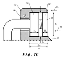
- Figure 1C shows a detail I of figure 1B .
- the fixing element 10 in the first embodiment comprises a base 12.
- the base has a base side 14.
- the base side 14, in use, is oriented towards the fence 2.
- the fixing element 10 also comprises a support clasp part 16.
- the support clasp part 16 is connected to a side 15 of the base 12 opposite the base side 14. More generally, the first through hole 22A can extend through the base 12 from the side 15 of the base 12 opposite the base side to the base side 14.
- the support clasp part 16 is arranged to claspingly engage the support 4.
- an inner diameter L 1 of the support clasp part 16 may correspond to an outer diameter L 2 of the support.
- the support clasp part can, as a result, fit tightly, and optionally claspingly, around the support. This can improve the clasping action of the support clasp part 16 onto the support 4.
- the fixing element 10 may be provided in combination with a clasp part 22 that is complementary to the fixing element 10, e.g. a bracket.
- the bracket 22 is preferably U-shaped.
- the bracket can for example be made substantially of steel, for example stainless steel.
- Figures 1A and 1B show an example of such a combination in operation, i.e. during the fixing or releasing, or in a fixed state.
- the fence 6 can be secured between the complementary clasp part 22 and the support 4, in particular between the base 12 and the complementary clasp part 22, as shown for example in figures 1A and 1B .
- the first and complementary clasp part can be provided separately from each other, optionally without the fence 6.
- the base 10 can be provided with at least a first through hole 24A.
- the first through hole 24A is arranged for receiving an end part 22A of the complementary clasp part 22.
- the first through hole 24A extends through the base 12 to the base side 14.
- the first through hole 24A is provided with a constriction 26.
- the base can comprise two base parts 12A and 12B that are separate from each other. Said separation can be achieved by providing an opening 25 between the base parts 12A and 12B.
- the base parts 12A and 12B may be connected to each other by means of the support clasp part 16. More in particular, the support clasp part 16 can form a deformable connection between the two base parts that allows displacement of the two base parts with respect to each other.
- the support clasp part can, for instance, connect the two base parts 12A and 12B resiliently with respect to each other.
- the support clasp part may be elastically deformable.
- the support clasp part can form a clip that can be snapped and/or shifted onto the support. This way, a clasping action of the support clasp part onto the support can be enabled or improved.
- the support clasp part comprises a plastic material.
- the support clasp part is made substantially of the plastic material. This allows the deformable connection between the two base parts to be achieved.
- the plastic material is preferably a fireproof plastic material. Such fireproof plastic material makes it harder for an intruder to disconnect the fence from the support.
- the whole fixing element is substantially made of the plastic material.
- a tightening element may be provided on the end part 22A of the complementary clasp part 22.
- the tightening element in use, engages the end part 22A.
- the tightening element may for example be a nut.
- the end part 22A can be threaded.
- the constriction 26 is formed in such a way that the tightening element 30 is blocked by the constriction. This blocking allows the securing through displacement of the tightening element 30 along the end part 22A, for example by tightening said nut.
- the complementary clasp part 22 can be fixed to the fixing element 10 by means of the tightening element 30.
- the fixing element 10 thus, more generally, cooperates with the complementary clasp part 22.
- the fixing element 10 and the complementary clasp part 22 can each engage a different side of the fence.
- the first through hole 24A and the tightening element 30 are dimensioned in such a way that, during the securing, the tightening element 30 is entirely contained within the first through hole 24.
- the sealing cap 32 is contained within the first through hole 24.
- the sealing cap 32 thereby blocks an access 34 to the tightening element 30 offered by the first through hole 24.
- a complete blocking by the sealing cap 32 can be particularly advantageous.
- the sealing cap 32 can, in use, be entirely contained within the through hole 24.
- the sealing cap 32 renders the removal of the tightening element 30 more difficult, and thus also makes it harder to disconnect the complementary clasp part 22 from the fixing element 10, and to disassemble the fence 2.
- the constriction can separate a narrower part 24' of a through hole 24A,B from a wider part 24" of a through hole 24A,B (see figures 1B and 1C ). From the above, it shall be clear that the tightening element 30 and the sealing cap 32 can, in use, be contained within the wider part of the through hole 24A,B. A depth H 1 of the wider part 24" of the first through hole 24A can therefore be greater than the sum of a height H 2 of the tightening element and a height H 3 of the sealing cap 32.
- the depth H 1 of the wider part of the first through hole 24A, the height H 2 of the tightening element 30 and the height H 3 of the sealing cap 32 can be measured in a direction parallel to a through hole direction 33 in which the first through hole extends.
- the wider part 24" of the first through hole 24A in other words, forms a cavity with an enlarged diameter (compared to the constriction) for receiving the nut.
- the depth H 1 of the cavity is greater than the height H 2 of the nut, so that room is left for receiving the sealing cap 32.
- the sealing cap can be substantially level with an outer side 35 of the base, as shown in figure 1C .
- the sealing cap is sunk inside the base 12.
- the sealing cap 32 is sunk inside the first through hole 24A.
- Such a sunk position generally renders loosening of the sealing cap more difficult. In both positions, the sealing cap is considered to be entirely contained within the first through hole.
- a fixing system 38 for fixing a fence to a fence support comprising the fixing element in the first embodiment, the complementary clasp part, and the sealing cap.
- the sealing cap 32 can comprise a deformable material.
- the deformable material may be plastically and/or elastically deformable.
- the deformable material can for example comprise a plastic material, and optionally be made substantially of the plastic material.
- the sealing cap 32 may for example comprise a rubber material, and optionally be made substantially of the rubber material.
- the sealing cap is made substantially of a fireproof plastic material. This can hinder or even prevent removal of the sealing cap 32 by burning the sealing cap 32, rendering the loosening of the tightening element 30 more difficult.
- the sealing cap 32 can for example be substantially cylindrical, or have the shape of a truncate cone or a cone frustum. Other frustum shapes are also possible.
- a cap size, e.g. an outer diameter D 1 , of the sealing cap 32 may be greater in its undeformed state than a through hole size, e.g. an inner diameter D 2 of the wider part 24" of the first through hole 24A.
- the through hole size can be measured in a direction perpendicular to the through hole direction 33 along which the first through hole extends.
- the cap size can be measured in a direction perpendicular to a cap longitudinal direction 36. In use, the cap longitudinal direction 36 is approximately parallel to the through hole direction 33 along which the first through hole extends.
- FIG. 1B shows the sealing cap 32 in its deformed state and entirely contained within the first through hole 22A. In the deformed state of figure 1B , the cap size D 1 of the sealing cap 32 in its deformed state equals the through hole size D 2 of the wider part of the first through hole 24A.
- the base 12 may also comprise a second through hole 24B.
- the through hole 24B is arranged for receiving a further end part 22B of the complementary clasp part 22.
- the end part 22A and the further end part 22B can for example, when the complementary clasp part 22 is U-shaped, be formed by a part of the legs of the U.
- the second through hole 24B extends through the base 12 to the base side 14. More generally, the second through hole 24B can have a similar shape to that of the first through hole 24A.
- the term "similar shape" can mean that the second through hole 24B may be provided with a further constriction such that a tightening element, which in use engages the further end part, is blocked by the further constriction and thus, in use, allows securing by displacement of the further tightening element along the further end part.
- the second through hole, an further sealing cap and the further tightening element can be dimensioned in such a way that, during the securing, the further tightening element is entirely contained within the second through hole and leaves room for the placement of the further sealing cap, which, in use, is also entirely contained within the second through hole and thereby blocks an access to the further tightening element offered by the second through hole. It shall thus also be clear that, more generally, one of the two base parts 12A,B can be provided with the first through hole, and the further of the two base parts can be provided with the second through hole.
- the further end part 22B of the complementary end part can be mechanically connected to the base of the support clasp part in a different way as well.
- the further end part 22B can be connected to the base by means of a hinge.
- the further end part 22B is connected to the base by means of an opening in the base 12 that cooperates with a protrusion of the complementary clasp part, the protrusion having a shape that corresponds to the opening so that the protrusion can engage with the opening in use.
- Figure 2 shows two fixing elements 10, each combined with a complementary clasp part 22.
- the complementary clasp part comprises a slab-shaped part 40 and bolts 42.
- the bolts are provided with bolt heads 44.
- the slab-shaped part 40 is provided with openings. These openings are dimensioned in such a way that the bolts, excluding the bolt heads, can be moved through the openings.
- the bolts form the end part 22A and further end part 22B of the complementary clasp part 22.
- the complementary clasp part is substantially rigid. This can be achieved by making the complementary clasp part 22 substantially from one piece.
- the complementary clasp part 22 may be formed by the bracket, which can be, for example, U-shaped. A leg of the bracket van form the end part 22A, and the other leg of the bracket can form the further end part 22B.
- the bracket can be mounted to the fixing element in two places, i.e. with the end part 22A and with the further end part 22B.
- a bracket-shaped complementary end part, mounted to the fixing element in two places, can further hinder the disconnection of the fixing element, since such a complementary end part can, at the base side 14 of the base 12 of the fixing element, be devoid of any points of application for disconnecting the complementary end part.
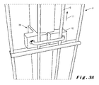
- Figure 3A shows a part of a fence 2 in a further embodiment according to the invention.
- the fence 2 is provided with the support 4, in this example the post 4, and with the fence 6.
- the fence 2 is further provided with a fixing element 10 in a second embodiment according to the invention.
- the fixing element 10 is arranged for fixing the fence 6 to the support 4 for the fence 6.
- Figure 3B shows the fixing element 10 in a cross section perpendicular to the longitudinal direction 11 of the post 4, as indicated in figure 3A .
- the fixing element 10 in the second embodiment comprises the base with the first base part 12A and the second base part 12B.
- the base has the base side 14, which, in use, can be oriented towards the fence 2.
- the fixing element 10 also comprises a support clasp part 16.
- the support clasp part 16 is connected to the a side 15 of the base 12 opposite the base side 14.
- the support clasp part 16 is arranged to claspingly engage the support 4.
- the support clasp part 16 and the base 12 can be rigidly connected to each other.
- the base 12 and the support clasp part 16 are made from one piece.
- the support clasp part 16 and the base 12 can substantially comprise a plastic material.
- the plastic material is preferably fireproof.
- Figures 3A and 3B also show the first through hole 24A, the second through hole 24B, and the complementary clasp part 22 with the end part 22A and the further end part 22B.
- Figures 3A and 3B show the complementary clasp part 22 in a configuration wherein the end parts 22A,B are contained within, respectively, the first opening 24A and the second opening 24B.
- Figure 3B also shows constrictions 26 separating a narrower part 24' of a through hole from a wider part 24" of that through hole.
- Figure 3B also shows the sealing cap 32.
- the sealing cap 32 has the shape of a cone frustum. Such a shape has a cap size that varies along the sealing cap, said cap size being measured in a direction perpendicular to a cap longitudinal direction 36 of the sealing cap.
- the sealing cap 32 can have a cap size, e.g. the outer diameter D 1 , that tapers along the sealing cap from a larger cap size to a smaller cap size.
- the smaller cap size can facilitate the placement of the sealing cap in the first through hole, in particular when the smaller cap size is smaller than an inner diameter of the first through hole.
- the larger cap size can bring about the clasping of the sealing cap within the first through hole.
- the sealing cap is substantially spherical.
- a diameter of the spherical sealing cap is preferably greater than the inner diameter of the first through hole.
- Such a spherical shape offers the advantage that the sealing cap can be placed inside the first through hole with an arbitrary orientation with respect to the first through hole. This facilitates the placement of the sealing cap.
- the fence 2 can be provided with a plurality of fixing systems, and thus with a plurality of sealing caps. For a fence with a relatively large amount of sealing caps 32, ease of placement of the sealing caps can become relatively important.
- the wider part of the first through hole can, for example, be cylindrical or have the shape of a cone frustum. Such shapes, and other shapes as well, may be considered as similar.
- an embodiment of a fixing system 38 according to the invention for fixing a fence to a support comprising the fixing element in the second embodiment, the complementary clasp part, and the sealing cap.
- an inner shape of the support clasp part 16 is at least partially similar to an outer shape of the support 4.
- Figures 1B and 3B show examples of such a similarity of shape.
- Figure 1B shows a round, in particular substantially circular inner shape of the support clasp part 16, combined with a round, in particular substantially circular outer shape of the support 4.
- Figure 1B shows a rectangular inner shape of the support clasp part 16, combined with a rectangular outer shape of the support 4.
- An inner shape of the support clasp part 16 which is at least partially similar to an outer shape of the support 4 can improve the clasping action of the support clasp part onto the support.
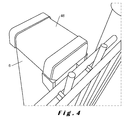
- Figure 4 shows the support 6 in combination with a covering element 46.
- the covering element may be executed as a covering cap.
- the covering element is arranged to be mounted to the support 6.
- the covering element is dimensioned in such a way that displacement of the support clasp part along the support 6 is blocked at the covering element 46. This way, removal of the fixing element from the support can be impeded.
- the fixing system can be used in a method according to the invention for fixing a fence to a fence support.
- An embodiment of such a method comprises the providing of a fixing system, comprising a fixing element and a clasp part complementary to the fixing element.
- the fixing element can for example be the fixing element 10 in the first or second embodiment, as shown in figures 1A-3B .
- the complementary clasp part can for example be the bracket 22 as shown in figures 1A , 1B , 3A , and 3B .
- the complementary clasp part may be formed by the assembly of a slab-shaped part 40 and bolts 42, as shown in figure 2 .
- other embodiments of the fixing element and the complementary clasp part are also possible.
- the embodiment of the method will be further described with reference to figures 1A-3B .
- the fixing element comprises the base side 14, which in use is oriented towards the fence 6, and also comprises the support clasp part 16, which is connected to a side of the base 12 opposite the base side.
- the embodiment of the method further comprises making the support clasp part 16 claspingly engage the support. This is preferably followed by the insertion of an end part 22A of the complementary clasp part 22 into the first through hole 24A, which is provided in the base 12, extends through the base 12 to the base side 14, and is provided with the constriction 26.
- the insertion of the complementary clasp part into the base is facilitated by the fact that the fixing element 10 can be mounted to the support 4 by means of the support clasp part 16.
- Said mounting allows the fixing element 10, and thus the base 12 with the first through hole 24A, to be permanently positioned onto the support 4, without requiring a user to support 4 the fixing element 10 thereafter. This allows the user to keep both hands free for installing and securing the fence 6. As a result, the fence 6 can be mounted to the support 4 by a single user.
- the embodiment of the method further comprises making the tightening element 30, e.g. the nut, claspingly engage the end part 22A.
- the tightening element 30 will be blocked by the constriction 26. This can be followed by securing the fence through displacement of the tightening element along the end part 24A.
- the tightening element can thus, in use and during the securing, be tightened against the constriction 26.
- the tightening element preferably is entirely contained within the first through hole. This way, the fence 6 can be secured onto the support 6 by means of the tightening element 30.
- the embodiment of the method further comprises blocking the access 34 to the tightening element 30 offered by the first through hole, by means of the sealing cap 32, so that the sealing cap 32 is also entirely contained within the first through hole 22A.
Landscapes
- Engineering & Computer Science (AREA)
- Architecture (AREA)
- Civil Engineering (AREA)
- Structural Engineering (AREA)
- Fencing (AREA)
- Refuge Islands, Traffic Blockers, Or Guard Fence (AREA)
Priority Applications (1)
| Application Number | Priority Date | Filing Date | Title |
|---|---|---|---|
| PL12199367T PL2607575T3 (pl) | 2011-12-23 | 2012-12-24 | Układ mocujący, ogrodzenie i sposób mocowania ogrodzenia do podpory ogrodzenia |
Applications Claiming Priority (1)
| Application Number | Priority Date | Filing Date | Title |
|---|---|---|---|
| BE2011/0753A BE1020487A5 (nl) | 2011-12-23 | 2011-12-23 | Bevestigingssysteem, bevestigingselement, hek, en werkwijze voor het bevestigen van een hekwerk aan een ondersteuning voor het hekwerk. |
Publications (2)
| Publication Number | Publication Date |
|---|---|
| EP2607575A1 true EP2607575A1 (fr) | 2013-06-26 |
| EP2607575B1 EP2607575B1 (fr) | 2014-02-26 |
Family
ID=47427256
Family Applications (1)
| Application Number | Title | Priority Date | Filing Date |
|---|---|---|---|
| EP12199367.9A Active EP2607575B1 (fr) | 2011-12-23 | 2012-12-24 | Système de fixation, clôture, et méthode de fixation d'une clôture sur un support de clôture |
Country Status (4)
| Country | Link |
|---|---|
| EP (1) | EP2607575B1 (fr) |
| BE (1) | BE1020487A5 (fr) |
| ES (1) | ES2456391T3 (fr) |
| PL (1) | PL2607575T3 (fr) |
Cited By (2)
| Publication number | Priority date | Publication date | Assignee | Title |
|---|---|---|---|---|
| EP3623540A1 (fr) * | 2018-09-17 | 2020-03-18 | Somain Securite | Dispositif de fixation d'un poteau sur un grillage |
| DE202020002022U1 (de) | 2020-05-08 | 2020-06-08 | Cetin Fidan | Befestigungsvorrichtung mit Arretierung für Zaunfelder |
Citations (4)
| Publication number | Priority date | Publication date | Assignee | Title |
|---|---|---|---|---|
| FR361920A (fr) * | 1905-11-17 | 1906-12-22 | Edouard Re | Cloture en ciment armé |
| GB2250757A (en) * | 1990-10-30 | 1992-06-17 | Tinsley Wire | Mesh fencing panel securing means |
| ES2170661A1 (es) * | 2000-05-05 | 2002-08-01 | Sotillos Jorge Antonio Saura | Valla modular. |
| EP2177694A2 (fr) * | 2008-10-17 | 2010-04-21 | Gust. Alberts GmbH & Co. KG | Pince de clôture pour la fixation d'une grille de clôture sur un poteau |
-
2011
- 2011-12-23 BE BE2011/0753A patent/BE1020487A5/nl active
-
2012
- 2012-12-24 ES ES12199367.9T patent/ES2456391T3/es active Active
- 2012-12-24 PL PL12199367T patent/PL2607575T3/pl unknown
- 2012-12-24 EP EP12199367.9A patent/EP2607575B1/fr active Active
Patent Citations (4)
| Publication number | Priority date | Publication date | Assignee | Title |
|---|---|---|---|---|
| FR361920A (fr) * | 1905-11-17 | 1906-12-22 | Edouard Re | Cloture en ciment armé |
| GB2250757A (en) * | 1990-10-30 | 1992-06-17 | Tinsley Wire | Mesh fencing panel securing means |
| ES2170661A1 (es) * | 2000-05-05 | 2002-08-01 | Sotillos Jorge Antonio Saura | Valla modular. |
| EP2177694A2 (fr) * | 2008-10-17 | 2010-04-21 | Gust. Alberts GmbH & Co. KG | Pince de clôture pour la fixation d'une grille de clôture sur un poteau |
Cited By (3)
| Publication number | Priority date | Publication date | Assignee | Title |
|---|---|---|---|---|
| EP3623540A1 (fr) * | 2018-09-17 | 2020-03-18 | Somain Securite | Dispositif de fixation d'un poteau sur un grillage |
| FR3085981A1 (fr) * | 2018-09-17 | 2020-03-20 | Somain Securite | Dispositif de fixation d'un poteau sur un grillage |
| DE202020002022U1 (de) | 2020-05-08 | 2020-06-08 | Cetin Fidan | Befestigungsvorrichtung mit Arretierung für Zaunfelder |
Also Published As
| Publication number | Publication date |
|---|---|
| BE1020487A5 (nl) | 2013-11-05 |
| EP2607575B1 (fr) | 2014-02-26 |
| PL2607575T3 (pl) | 2014-06-30 |
| ES2456391T3 (es) | 2014-04-22 |
Similar Documents
| Publication | Publication Date | Title |
|---|---|---|
| KR100954965B1 (ko) | 메쉬휀스 결속구 | |
| US9777500B1 (en) | Pole reinforcement | |
| KR101064460B1 (ko) | 선박 건조를 위한 족장용 안전난간 | |
| EP3642431B1 (fr) | Poteau de clôture pour une clôture souple | |
| EP2607575A1 (fr) | Système de fixation, élément de fixation, clôture, et méthode de fixation d'une clôture sur un support clôture | |
| JP2020092713A (ja) | 動物用恒久柵におけるワイヤ保持用のポスト | |
| EP2243903A1 (fr) | Système de fermeture pour des treillis de clôture | |
| EP2627840B1 (fr) | Clôture | |
| JP5922187B2 (ja) | 引込用鋼管柱用の継柱 | |
| KR101876320B1 (ko) | 동물보호펜스 | |
| KR200433073Y1 (ko) | 심신단련 시스템용 펜스지주 결속구 | |
| EP3045616B1 (fr) | Support pour poteau métallique | |
| KR200389184Y1 (ko) | 차단망 고정용 프레임 | |
| KR102088057B1 (ko) | 전신주 고정밴드 | |
| KR20110120535A (ko) | 야생동물 보호용 펜스 및 그 설치방법 | |
| KR101188618B1 (ko) | 밴딩파이프를 이용한 옥외용차양과 이에 사용되는 마감장치 | |
| KR101789465B1 (ko) | 와이어 프레임 및 그의 고정장치를 갖는 능형망 울타리 | |
| KR101477754B1 (ko) | 볼트공이 없는 무천공형 울타리용 지주 | |
| KR200367716Y1 (ko) | 알루미늄제 다목적 휀스 | |
| JP2016125300A (ja) | 防護柵および防護柵の製造方法 | |
| KR101516118B1 (ko) | 건축물 천정 시공 장치 | |
| KR200398381Y1 (ko) | 지수판 자립 고정체 | |
| KR101824858B1 (ko) | 울타리 철망 고정 클립 | |
| KR200444608Y1 (ko) | 클립을 이용한 펜스 조립장치 | |
| CN112292792B (zh) | 用于高压绝缘子的防污装置 |
Legal Events
| Date | Code | Title | Description |
|---|---|---|---|
| AK | Designated contracting states |
Kind code of ref document: A1 Designated state(s): AL AT BE BG CH CY CZ DE DK EE ES FI FR GB GR HR HU IE IS IT LI LT LU LV MC MK MT NL NO PL PT RO RS SE SI SK SM TR |
|
| AX | Request for extension of the european patent |
Extension state: BA ME |
|
| PUAI | Public reference made under article 153(3) epc to a published international application that has entered the european phase |
Free format text: ORIGINAL CODE: 0009012 |
|
| 17P | Request for examination filed |
Effective date: 20130905 |
|
| RBV | Designated contracting states (corrected) |
Designated state(s): AL AT BE BG CH CY CZ DE DK EE ES FI FR GB GR HR HU IE IS IT LI LT LU LV MC MK MT NL NO PL PT RO RS SE SI SK SM TR |
|
| GRAP | Despatch of communication of intention to grant a patent |
Free format text: ORIGINAL CODE: EPIDOSNIGR1 |
|
| INTG | Intention to grant announced |
Effective date: 20131104 |
|
| GRAS | Grant fee paid |
Free format text: ORIGINAL CODE: EPIDOSNIGR3 |
|
| GRAA | (expected) grant |
Free format text: ORIGINAL CODE: 0009210 |
|
| AK | Designated contracting states |
Kind code of ref document: B1 Designated state(s): AL AT BE BG CH CY CZ DE DK EE ES FI FR GB GR HR HU IE IS IT LI LT LU LV MC MK MT NL NO PL PT RO RS SE SI SK SM TR |
|
| REG | Reference to a national code |
Ref country code: GB Ref legal event code: FG4D |
|
| REG | Reference to a national code |
Ref country code: CH Ref legal event code: EP |
|
| REG | Reference to a national code |
Ref country code: AT Ref legal event code: REF Ref document number: 653718 Country of ref document: AT Kind code of ref document: T Effective date: 20140315 |
|
| REG | Reference to a national code |
Ref country code: NL Ref legal event code: T3 |
|
| REG | Reference to a national code |
Ref country code: DE Ref legal event code: R096 Ref document number: 602012000964 Country of ref document: DE Effective date: 20140403 |
|
| REG | Reference to a national code |
Ref country code: IE Ref legal event code: FG4D |
|
| REG | Reference to a national code |
Ref country code: ES Ref legal event code: FG2A Ref document number: 2456391 Country of ref document: ES Kind code of ref document: T3 Effective date: 20140422 |
|
| REG | Reference to a national code |
Ref country code: PL Ref legal event code: T3 |
|
| REG | Reference to a national code |
Ref country code: AT Ref legal event code: MK05 Ref document number: 653718 Country of ref document: AT Kind code of ref document: T Effective date: 20140226 |
|
| PG25 | Lapsed in a contracting state [announced via postgrant information from national office to epo] |
Ref country code: NO Free format text: LAPSE BECAUSE OF FAILURE TO SUBMIT A TRANSLATION OF THE DESCRIPTION OR TO PAY THE FEE WITHIN THE PRESCRIBED TIME-LIMIT Effective date: 20140526 Ref country code: IS Free format text: LAPSE BECAUSE OF FAILURE TO SUBMIT A TRANSLATION OF THE DESCRIPTION OR TO PAY THE FEE WITHIN THE PRESCRIBED TIME-LIMIT Effective date: 20140626 |
|
| PG25 | Lapsed in a contracting state [announced via postgrant information from national office to epo] |
Ref country code: PT Free format text: LAPSE BECAUSE OF FAILURE TO SUBMIT A TRANSLATION OF THE DESCRIPTION OR TO PAY THE FEE WITHIN THE PRESCRIBED TIME-LIMIT Effective date: 20140626 Ref country code: AT Free format text: LAPSE BECAUSE OF FAILURE TO SUBMIT A TRANSLATION OF THE DESCRIPTION OR TO PAY THE FEE WITHIN THE PRESCRIBED TIME-LIMIT Effective date: 20140226 Ref country code: FI Free format text: LAPSE BECAUSE OF FAILURE TO SUBMIT A TRANSLATION OF THE DESCRIPTION OR TO PAY THE FEE WITHIN THE PRESCRIBED TIME-LIMIT Effective date: 20140226 Ref country code: SE Free format text: LAPSE BECAUSE OF FAILURE TO SUBMIT A TRANSLATION OF THE DESCRIPTION OR TO PAY THE FEE WITHIN THE PRESCRIBED TIME-LIMIT Effective date: 20140226 Ref country code: CY Free format text: LAPSE BECAUSE OF FAILURE TO SUBMIT A TRANSLATION OF THE DESCRIPTION OR TO PAY THE FEE WITHIN THE PRESCRIBED TIME-LIMIT Effective date: 20140226 |
|
| PG25 | Lapsed in a contracting state [announced via postgrant information from national office to epo] |
Ref country code: LV Free format text: LAPSE BECAUSE OF FAILURE TO SUBMIT A TRANSLATION OF THE DESCRIPTION OR TO PAY THE FEE WITHIN THE PRESCRIBED TIME-LIMIT Effective date: 20140226 Ref country code: HR Free format text: LAPSE BECAUSE OF FAILURE TO SUBMIT A TRANSLATION OF THE DESCRIPTION OR TO PAY THE FEE WITHIN THE PRESCRIBED TIME-LIMIT Effective date: 20140226 |
|
| PG25 | Lapsed in a contracting state [announced via postgrant information from national office to epo] |
Ref country code: EE Free format text: LAPSE BECAUSE OF FAILURE TO SUBMIT A TRANSLATION OF THE DESCRIPTION OR TO PAY THE FEE WITHIN THE PRESCRIBED TIME-LIMIT Effective date: 20140226 Ref country code: RO Free format text: LAPSE BECAUSE OF FAILURE TO SUBMIT A TRANSLATION OF THE DESCRIPTION OR TO PAY THE FEE WITHIN THE PRESCRIBED TIME-LIMIT Effective date: 20140226 Ref country code: DK Free format text: LAPSE BECAUSE OF FAILURE TO SUBMIT A TRANSLATION OF THE DESCRIPTION OR TO PAY THE FEE WITHIN THE PRESCRIBED TIME-LIMIT Effective date: 20140226 Ref country code: CZ Free format text: LAPSE BECAUSE OF FAILURE TO SUBMIT A TRANSLATION OF THE DESCRIPTION OR TO PAY THE FEE WITHIN THE PRESCRIBED TIME-LIMIT Effective date: 20140226 |
|
| REG | Reference to a national code |
Ref country code: DE Ref legal event code: R097 Ref document number: 602012000964 Country of ref document: DE |
|
| PG25 | Lapsed in a contracting state [announced via postgrant information from national office to epo] |
Ref country code: SK Free format text: LAPSE BECAUSE OF FAILURE TO SUBMIT A TRANSLATION OF THE DESCRIPTION OR TO PAY THE FEE WITHIN THE PRESCRIBED TIME-LIMIT Effective date: 20140226 |
|
| REG | Reference to a national code |
Ref country code: HU Ref legal event code: AG4A Ref document number: E021130 Country of ref document: HU |
|
| PLBE | No opposition filed within time limit |
Free format text: ORIGINAL CODE: 0009261 |
|
| STAA | Information on the status of an ep patent application or granted ep patent |
Free format text: STATUS: NO OPPOSITION FILED WITHIN TIME LIMIT |
|
| 26N | No opposition filed |
Effective date: 20141127 |
|
| REG | Reference to a national code |
Ref country code: DE Ref legal event code: R097 Ref document number: 602012000964 Country of ref document: DE Effective date: 20141127 |
|
| PG25 | Lapsed in a contracting state [announced via postgrant information from national office to epo] |
Ref country code: SI Free format text: LAPSE BECAUSE OF FAILURE TO SUBMIT A TRANSLATION OF THE DESCRIPTION OR TO PAY THE FEE WITHIN THE PRESCRIBED TIME-LIMIT Effective date: 20140226 |
|
| REG | Reference to a national code |
Ref country code: FR Ref legal event code: PLFP Year of fee payment: 4 |
|
| PG25 | Lapsed in a contracting state [announced via postgrant information from national office to epo] |
Ref country code: MC Free format text: LAPSE BECAUSE OF FAILURE TO SUBMIT A TRANSLATION OF THE DESCRIPTION OR TO PAY THE FEE WITHIN THE PRESCRIBED TIME-LIMIT Effective date: 20140226 |
|
| PG25 | Lapsed in a contracting state [announced via postgrant information from national office to epo] |
Ref country code: RS Free format text: LAPSE BECAUSE OF FAILURE TO SUBMIT A TRANSLATION OF THE DESCRIPTION OR TO PAY THE FEE WITHIN THE PRESCRIBED TIME-LIMIT Effective date: 20140226 Ref country code: BG Free format text: LAPSE BECAUSE OF FAILURE TO SUBMIT A TRANSLATION OF THE DESCRIPTION OR TO PAY THE FEE WITHIN THE PRESCRIBED TIME-LIMIT Effective date: 20140226 Ref country code: GR Free format text: LAPSE BECAUSE OF FAILURE TO SUBMIT A TRANSLATION OF THE DESCRIPTION OR TO PAY THE FEE WITHIN THE PRESCRIBED TIME-LIMIT Effective date: 20140527 |
|
| PG25 | Lapsed in a contracting state [announced via postgrant information from national office to epo] |
Ref country code: MT Free format text: LAPSE BECAUSE OF FAILURE TO SUBMIT A TRANSLATION OF THE DESCRIPTION OR TO PAY THE FEE WITHIN THE PRESCRIBED TIME-LIMIT Effective date: 20140226 |
|
| REG | Reference to a national code |
Ref country code: CH Ref legal event code: PL |
|
| PG25 | Lapsed in a contracting state [announced via postgrant information from national office to epo] |
Ref country code: CH Free format text: LAPSE BECAUSE OF NON-PAYMENT OF DUE FEES Effective date: 20151231 Ref country code: LI Free format text: LAPSE BECAUSE OF NON-PAYMENT OF DUE FEES Effective date: 20151231 |
|
| REG | Reference to a national code |
Ref country code: FR Ref legal event code: PLFP Year of fee payment: 5 |
|
| PG25 | Lapsed in a contracting state [announced via postgrant information from national office to epo] |
Ref country code: SM Free format text: LAPSE BECAUSE OF FAILURE TO SUBMIT A TRANSLATION OF THE DESCRIPTION OR TO PAY THE FEE WITHIN THE PRESCRIBED TIME-LIMIT Effective date: 20140226 |
|
| REG | Reference to a national code |
Ref country code: FR Ref legal event code: PLFP Year of fee payment: 6 |
|
| PG25 | Lapsed in a contracting state [announced via postgrant information from national office to epo] |
Ref country code: MK Free format text: LAPSE BECAUSE OF FAILURE TO SUBMIT A TRANSLATION OF THE DESCRIPTION OR TO PAY THE FEE WITHIN THE PRESCRIBED TIME-LIMIT Effective date: 20140226 |
|
| PG25 | Lapsed in a contracting state [announced via postgrant information from national office to epo] |
Ref country code: AL Free format text: LAPSE BECAUSE OF FAILURE TO SUBMIT A TRANSLATION OF THE DESCRIPTION OR TO PAY THE FEE WITHIN THE PRESCRIBED TIME-LIMIT Effective date: 20140226 |
|
| REG | Reference to a national code |
Ref country code: NL Ref legal event code: PD Owner name: DEL PONTI BV; BE Free format text: DETAILS ASSIGNMENT: CHANGE OF OWNER(S), DEMERGER; FORMER OWNER NAME: DEL PONTI Effective date: 20201110 |
|
| REG | Reference to a national code |
Ref country code: LU Ref legal event code: HC Owner name: DEL PONTI; BE Effective date: 20210510 Ref country code: LU Ref legal event code: PD Owner name: DEL PONTI BV; BE Effective date: 20210510 |
|
| REG | Reference to a national code |
Ref country code: BE Ref legal event code: PD Owner name: DEL PONTI BV; BE Free format text: DETAILS ASSIGNMENT: CHANGE OF OWNER(S), ASSIGNMENT Effective date: 20210511 |
|
| REG | Reference to a national code |
Ref country code: DE Ref legal event code: R081 Ref document number: 602012000964 Country of ref document: DE Owner name: DEL PONTI BV, BE Free format text: FORMER OWNER: DEL PONTI, HECHTEL-EKSEL, BE |
|
| REG | Reference to a national code |
Ref country code: ES Ref legal event code: PC2A Owner name: DEL PONTI BV Effective date: 20220307 |
|
| REG | Reference to a national code |
Ref country code: GB Ref legal event code: 732E Free format text: REGISTERED BETWEEN 20220217 AND 20220223 |
|
| REG | Reference to a national code |
Ref country code: HU Ref legal event code: GB9C Owner name: DEL PONTI BV, BE Free format text: FORMER OWNER(S): DEL PONTI, BE Ref country code: HU Ref legal event code: FH1C Free format text: FORMER REPRESENTATIVE(S): DR. JAKABNE MOLNAR JUDIT, SBGK SZABADALMI UEGYVIVOEI IRODA, HU Representative=s name: SBGK SZABADALMI UEGYVIVOEI IRODA, HU |
|
| PGFP | Annual fee paid to national office [announced via postgrant information from national office to epo] |
Ref country code: GB Payment date: 20231219 Year of fee payment: 12 |
|
| PGFP | Annual fee paid to national office [announced via postgrant information from national office to epo] |
Ref country code: IT Payment date: 20231221 Year of fee payment: 12 Ref country code: IE Payment date: 20231219 Year of fee payment: 12 |
|
| GBPC | Gb: european patent ceased through non-payment of renewal fee |
Effective date: 20241224 |
|
| PG25 | Lapsed in a contracting state [announced via postgrant information from national office to epo] |
Ref country code: IT Free format text: LAPSE BECAUSE OF NON-PAYMENT OF DUE FEES Effective date: 20241224 |
|
| PG25 | Lapsed in a contracting state [announced via postgrant information from national office to epo] |
Ref country code: GB Free format text: LAPSE BECAUSE OF NON-PAYMENT OF DUE FEES Effective date: 20241224 |
|
| PG25 | Lapsed in a contracting state [announced via postgrant information from national office to epo] |
Ref country code: IE Free format text: LAPSE BECAUSE OF NON-PAYMENT OF DUE FEES Effective date: 20241224 |
|
| PGFP | Annual fee paid to national office [announced via postgrant information from national office to epo] |
Ref country code: NL Payment date: 20251112 Year of fee payment: 14 |
|
| PGFP | Annual fee paid to national office [announced via postgrant information from national office to epo] |
Ref country code: LT Payment date: 20251203 Year of fee payment: 14 |
|
| PGFP | Annual fee paid to national office [announced via postgrant information from national office to epo] |
Ref country code: LU Payment date: 20251222 Year of fee payment: 14 Ref country code: HU Payment date: 20251217 Year of fee payment: 14 Ref country code: FR Payment date: 20251112 Year of fee payment: 14 |
|
| PGFP | Annual fee paid to national office [announced via postgrant information from national office to epo] |
Ref country code: BE Payment date: 20251112 Year of fee payment: 14 Ref country code: TR Payment date: 20251204 Year of fee payment: 14 |
|
| PGFP | Annual fee paid to national office [announced via postgrant information from national office to epo] |
Ref country code: PL Payment date: 20251128 Year of fee payment: 14 |
|
| PGFP | Annual fee paid to national office [announced via postgrant information from national office to epo] |
Ref country code: ES Payment date: 20260122 Year of fee payment: 14 |
|
| PGFP | Annual fee paid to national office [announced via postgrant information from national office to epo] |
Ref country code: DE Payment date: 20251229 Year of fee payment: 14 |