EP2607610A2 - Scherblatt mit verstärkter Zähigkeit für Ausbruchverhütungsventil - Google Patents
Scherblatt mit verstärkter Zähigkeit für Ausbruchverhütungsventil Download PDFInfo
- Publication number
- EP2607610A2 EP2607610A2 EP12196361.5A EP12196361A EP2607610A2 EP 2607610 A2 EP2607610 A2 EP 2607610A2 EP 12196361 A EP12196361 A EP 12196361A EP 2607610 A2 EP2607610 A2 EP 2607610A2
- Authority
- EP
- European Patent Office
- Prior art keywords
- ram
- cutting
- coating
- compound
- blowout preventer
- Prior art date
- Legal status (The legal status is an assumption and is not a legal conclusion. Google has not performed a legal analysis and makes no representation as to the accuracy of the status listed.)
- Withdrawn
Links
- 238000005520 cutting process Methods 0.000 claims abstract description 111
- 150000001875 compounds Chemical class 0.000 claims abstract description 28
- 238000000576 coating method Methods 0.000 claims description 45
- 239000011248 coating agent Substances 0.000 claims description 44
- 238000000034 method Methods 0.000 claims description 32
- 238000005240 physical vapour deposition Methods 0.000 claims description 16
- 230000008569 process Effects 0.000 claims description 16
- IJGRMHOSHXDMSA-UHFFFAOYSA-N Atomic nitrogen Chemical compound N#N IJGRMHOSHXDMSA-UHFFFAOYSA-N 0.000 claims description 12
- 230000001965 increasing effect Effects 0.000 claims description 8
- RTAQQCXQSZGOHL-UHFFFAOYSA-N Titanium Chemical compound [Ti] RTAQQCXQSZGOHL-UHFFFAOYSA-N 0.000 claims description 7
- 238000005229 chemical vapour deposition Methods 0.000 claims description 7
- 229910052719 titanium Inorganic materials 0.000 claims description 7
- 239000010936 titanium Substances 0.000 claims description 7
- 229910052757 nitrogen Inorganic materials 0.000 claims description 6
- NRTOMJZYCJJWKI-UHFFFAOYSA-N Titanium nitride Chemical compound [Ti]#N NRTOMJZYCJJWKI-UHFFFAOYSA-N 0.000 claims description 5
- UQZIWOQVLUASCR-UHFFFAOYSA-N alumane;titanium Chemical compound [AlH3].[Ti] UQZIWOQVLUASCR-UHFFFAOYSA-N 0.000 claims description 5
- 230000003247 decreasing effect Effects 0.000 claims description 5
- 239000002241 glass-ceramic Substances 0.000 claims description 4
- 239000011159 matrix material Substances 0.000 claims description 4
- CYKMNKXPYXUVPR-UHFFFAOYSA-N [C].[Ti] Chemical compound [C].[Ti] CYKMNKXPYXUVPR-UHFFFAOYSA-N 0.000 claims description 3
- 238000010008 shearing Methods 0.000 description 7
- 239000007789 gas Substances 0.000 description 4
- 239000000463 material Substances 0.000 description 4
- 238000005553 drilling Methods 0.000 description 3
- 238000007789 sealing Methods 0.000 description 3
- -1 but not limited to Substances 0.000 description 2
- 230000000873 masking effect Effects 0.000 description 2
- VYZAMTAEIAYCRO-UHFFFAOYSA-N Chromium Chemical compound [Cr] VYZAMTAEIAYCRO-UHFFFAOYSA-N 0.000 description 1
- 229910000760 Hardened steel Inorganic materials 0.000 description 1
- 229910052804 chromium Inorganic materials 0.000 description 1
- 239000011651 chromium Substances 0.000 description 1
- 238000010276 construction Methods 0.000 description 1
- 230000007123 defense Effects 0.000 description 1
- 230000002708 enhancing effect Effects 0.000 description 1
- 239000012530 fluid Substances 0.000 description 1
- 230000006870 function Effects 0.000 description 1
- 230000007246 mechanism Effects 0.000 description 1
- 238000012986 modification Methods 0.000 description 1
- 230000004048 modification Effects 0.000 description 1
- 238000012544 monitoring process Methods 0.000 description 1
- TWNQGVIAIRXVLR-UHFFFAOYSA-N oxo(oxoalumanyloxy)alumane Chemical compound O=[Al]O[Al]=O TWNQGVIAIRXVLR-UHFFFAOYSA-N 0.000 description 1
- 230000009467 reduction Effects 0.000 description 1
Images


Classifications
-
- E—FIXED CONSTRUCTIONS
- E21—EARTH OR ROCK DRILLING; MINING
- E21B—EARTH OR ROCK DRILLING; OBTAINING OIL, GAS, WATER, SOLUBLE OR MELTABLE MATERIALS OR A SLURRY OF MINERALS FROM WELLS
- E21B33/00—Sealing or packing boreholes or wells
- E21B33/02—Surface sealing or packing
- E21B33/03—Well heads; Setting-up thereof
- E21B33/06—Blow-out preventers, i.e. apparatus closing around a drill pipe, e.g. annular blow-out preventers
- E21B33/061—Ram-type blow-out preventers, e.g. with pivoting rams
- E21B33/062—Ram-type blow-out preventers, e.g. with pivoting rams with sliding rams
- E21B33/063—Ram-type blow-out preventers, e.g. with pivoting rams with sliding rams for shearing drill pipes
Definitions
- Embodiments of the subject matter disclosed herein generally relate to devices and, more particularly, to mechanisms and techniques for enhancing the toughness and improving the coefficient of friction of a shear blade for a ram-type blowout preventer (BOP).
- BOP blowout preventer
- Blowout preventers are large, specialized valves for sealing, controlling and monitoring oil and gas wells.
- blowout preventers are intended to prevent tubing (e.g. drill pipe and well casing), tools and drilling fluid from being blown out of the wellbore when a blowout threatens.
- Blowout preventers are critical to the safety of the drilling crew, the drilling rig and the environment and accordingly are intended to be fail-safe devices.
- a ram-type blowout preventer operates in a fashion similar to a gate valve, but uses a pair of opposing rams extending from opposite sides of the wellbore toward the center of the wellbore to restrict or prevent flow.
- One of four different types of ram blocks (pipe, blind, shear and blind shear) are used depending on the intended application.
- shear and blind shear ram blocks have shear blades attached to the ram blocks that cut through the well casing and drill string or cut through the well casing and drill string while sealing the wellbore respectively.
- blowout preventer BOP
- market pressure driven by the failure of these last line of defense devices, to solve this expensive and environmentally damaging problem has led to the desire to create a shear blade capable of reliably cutting the tubulars, and possibly well strings, associated with the oil and gas wells in use and exploration today.
- a shear ram assembly for operation in a ram-type blowout preventer apparatus comprising a plurality of hardened cutting blades wherein the plurality of hardened cutting blades are coated with a compound for increasing the hardness and decreasing the coefficient of friction of the hardened cutting blades.
- a plurality of blocks to which the coated plurality of cutting blades are attached or formed integrally therein.
- the ram-type blowout preventer apparatus includes a casing for enclosing the ram-type blowout preventer components, a plurality of opposing actuators connected to the casing for actuating a plurality of blocks attached to the actuators and a plurality of hardened cutting blades attached to the blocks wherein the plurality of hardened cutting blades are coated with a compound for preventing cutting surface deformation and reducing required shear force during cutting.
- the exemplary method embodiment comprises applying a thin coating of a compound to the plurality of cutting blades wherein the compound comprises titanium and nitrogen.
- the exemplary method embodiment continues with applying the coating by a physical vapor deposition process that increases the hardness while reducing the coefficient of friction of the plurality of cutting blades.
- Ram-type blowout preventers comprise a casing, a pair of opposing cutting blades attached to ram blocks and a pair of actuators for imparting motion to the ram blocks.
- an exemplary embodiment illustrates a ram-type blowout preventer 100.
- the exemplary embodiment ram-type blowout preventer 100 includes cutting blades 102, 104 with a coating 112, 114 and ram blocks 106, 108.
- a ram-type blowout preventer 100 casing 110 is illustrated and contains the components of the ram-type blowout preventer 100.
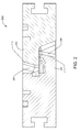
- the cutting blades 102, 104 have sheared the tubular 112 in the well bore 114.
- the coating illustrated at 112, 114 can be applied to the entire cutting blade 104, 106 or it can be applied to specific locations of the cutting blade. Further it should be noted that the cutting blade can be constructed of a hardened material.
- an exemplary embodiment 200 illustrates a cross section of a pair of cutting blades 202, 204 for attachment to the ram blocks of a ram-type blowout preventer. Illustrated at 206, 208 of figure 2 is a coating applied to contact locations 210, 212 involved in a shear cutting operation when the ram-type blowout preventer is actuated. It should be noted that the coating can be applied to the entire cutting blade based on factors such as, but not limited to, the ease of masking areas not desired for coating or to other contact areas of the cutting blade 202, 204.
- An exemplary embodiment ram-type blowout preventer has shear rams comprising a ram block or carrier and cutting blades.
- the exemplary embodiment cutting blades constructed of a hardened material, are attached to the ram blocks such that the cutting blades extend, under movement of the ram blocks, from opposite sides of the well bore and meet at the center of the well bore.
- FIG 3 a cross section drawing of an exploded view of the end of a cutting blade 300 for a ram-type blowout preventer is illustrated.
- the end of the cutting blade 302 depicts a coating 304, 306 on the edge 308 and the face 310 of the cutting blade 302.
- the cutting blade can be masked and coated only on these bearing surfaces or it can be coated in its entirety for ease of coating.
- the cutting blade 300 shown in figure 3 can be configured to be attached to a corresponding ram block, for example, by screws.
- the cutting blade 300 may be in fact an integral part of the ram block if the ram block is machined with a cutting profile on the front of the block. In this way, the coating is applied directly to the cutting profile of the block as discussed later.
- a cutting blade when referring to a cutting blade it is understood a blade that can be attached to the ram block or a blade that is machined directly into the ram block.
- the hardness of the cutting blades is increased and the coefficient of friction of the cutting blades is decreased by applying a coating to the cutting blades.
- the blade and the cutting blade (which may be a single piece) are made of hardened steel.
- the coating is applied with a physical vapor deposition (PVD) process.
- the coating is applied with a chemical vapor deposition (CVD) process.
- the exemplary embodiment process selected for applying the coating is a function of factors such as, but not limited to, the material of construction of the cutting blades, the desired properties of the coated cutting blades (i.e.
- the increased hardness and reduction of the coefficient of friction of the coated cutting blades prevents the cutting edge of the cutting blades from deforming during the shearing process and lowers the required shearing forces.
- the coating is applied to at least the top and the front face of the cutting blades but can be applied to the entire blade for ease of applying the coating.
- ease of applying the coating refers to eliminating the need for masking areas that do not require a coating to meet the mechanical requirements of the cutting blades.
- Coatings associated with the exemplary embodiments comprise materials such as, but not limited to, titanium, aluminum oxide and chromium.
- the cutting blades are coated with compounds such as, but not limited to, titanium nitride (TiN), a glass ceramic matrix of titanium aluminum oxynitride (TiAlON), titanium carbon nitride (TiCN), etc.
- the cutting blades of a ram-type blowout preventer are coated with a titanium nitride or a titanium aluminum oxynitride compound by a physical vapor deposition (PVD) process.
- PVD physical vapor deposition
- the exemplary embodiment process is carried out at a temperature of approximately 300 °F and a coating, of one of the aforementioned compounds, of approximately 0.5 ⁇ m to approximately 4 ⁇ m is applied to the entire surface of the cutting blades.
- the cutting blades are then attached to the ram blocks installed in the ram-type blowout preventer (BOP).
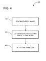
- a flowchart for an exemplary method embodiment for reducing the force required shearing an oilfield tubular and preventing deformation of the cutting blades associated with a ram-type blowout preventer is depicted.
- a cutting blade is coated with a previously described compound by either of the physical vapor deposition or chemical vapor deposition processes.
- the cutting blade can be masked such that the coating is applied only to bearing surfaces or the cutting blades can be completely coated.
- the coated cutting blade is attached to a ram block associated with the ram-type blowout preventer. It should be noted that more than one cutting blade, and correspondingly more than one ram block, can be associated with a single ram-type blowout preventer.
- the ram blocks are actuated which drives the coated cutting blades together shearing the oilfield tubular.
- the cutting blades can remain in the actuated position as a seal for the wellbore or they can be retracted allowing the remaining tubular above the cutting blades to be retracted.
- the disclosed exemplary embodiments provide a device and a method for coating the cutting blades of a ram-type blowout preventer and integrating the coated cutting blades into the ram-type blowout preventer. It should be understood that this description is not intended to limit the invention. On the contrary, the exemplary embodiments are intended to cover alternatives, modifications and equivalents, which are included in the spirit and scope of the invention as defined by the appended claims. Further, in the detailed description of the exemplary embodiments, numerous specific details are set forth in order to provide a comprehensive understanding of the claimed invention. However, one skilled in the art would understand that various embodiments may be practiced without such specific details.
Landscapes
- Geology (AREA)
- Life Sciences & Earth Sciences (AREA)
- Engineering & Computer Science (AREA)
- Mining & Mineral Resources (AREA)
- Environmental & Geological Engineering (AREA)
- Fluid Mechanics (AREA)
- Physics & Mathematics (AREA)
- General Life Sciences & Earth Sciences (AREA)
- Geochemistry & Mineralogy (AREA)
- Physical Vapour Deposition (AREA)
- Shearing Machines (AREA)
- User Interface Of Digital Computer (AREA)
- Chemical Vapour Deposition (AREA)
- Cutting Tools, Boring Holders, And Turrets (AREA)
Applications Claiming Priority (1)
| Application Number | Priority Date | Filing Date | Title |
|---|---|---|---|
| US13/331,494 US20130153204A1 (en) | 2011-12-20 | 2011-12-20 | Ram bop shear blade process to enhance the toughness |
Publications (1)
| Publication Number | Publication Date |
|---|---|
| EP2607610A2 true EP2607610A2 (de) | 2013-06-26 |
Family
ID=47297028
Family Applications (1)
| Application Number | Title | Priority Date | Filing Date |
|---|---|---|---|
| EP12196361.5A Withdrawn EP2607610A2 (de) | 2011-12-20 | 2012-12-10 | Scherblatt mit verstärkter Zähigkeit für Ausbruchverhütungsventil |
Country Status (6)
| Country | Link |
|---|---|
| US (1) | US20130153204A1 (de) |
| EP (1) | EP2607610A2 (de) |
| CN (1) | CN103174394A (de) |
| AU (1) | AU2012261736A1 (de) |
| BR (1) | BR102012031579A2 (de) |
| SG (2) | SG191510A1 (de) |
Families Citing this family (12)
| Publication number | Priority date | Publication date | Assignee | Title |
|---|---|---|---|---|
| WO2017039740A1 (en) * | 2015-09-01 | 2017-03-09 | Cameron International Corporation | Blowout preventer including blind seal assembly |
| US10550660B2 (en) | 2015-11-09 | 2020-02-04 | Hydril USA Distribution LLC | Blind shear ram |
| GB201614712D0 (en) | 2016-08-31 | 2016-10-12 | Enovate Systems Ltd | Improved shear blade |
| US10577884B2 (en) * | 2017-03-31 | 2020-03-03 | General Electric Company | Blowout prevention system including blind shear ram |
| NO344001B1 (en) * | 2017-11-29 | 2019-08-12 | Smart Installations As | Method for cutting a tubular structure at a drill floor and a cutting tool for carrying out such method |
| US11401770B2 (en) | 2018-04-06 | 2022-08-02 | Hydril USA Distribution LLC | Hardfaced metal surface and method of manufacture |
| US11286740B2 (en) * | 2019-04-21 | 2022-03-29 | Schlumberger Technology Corporation | Blowout preventer shearing ram |
| EP3959415B1 (de) | 2019-04-21 | 2024-04-03 | Services Pétroliers Schlumberger | Scherbacke für ausbruchschieber |
| US12006781B2 (en) | 2019-04-21 | 2024-06-11 | Schlumberger Technology Corporation | Blowout preventer with multiple application ram blades |
| USD973734S1 (en) * | 2019-08-06 | 2022-12-27 | Nxl Technologies Inc. | Blind shear |
| US11919086B2 (en) * | 2020-12-16 | 2024-03-05 | Schlumberger Technology Corporation | Hot isostatic pressing (HIP) fabrication of multi-metallic components for pressure-controlling equipment |
| US12247456B1 (en) | 2023-08-24 | 2025-03-11 | Schlumberger Technology Corporation | Blowout preventer system and method utilizing shear ram buttress |
Family Cites Families (7)
| Publication number | Priority date | Publication date | Assignee | Title |
|---|---|---|---|---|
| US4132266A (en) * | 1978-04-06 | 1979-01-02 | Cameron Iron Works, Inc. | Pipe shearing ram assembly for blowout preventer |
| US4696352A (en) * | 1986-03-17 | 1987-09-29 | Gte Laboratories Incorporated | Insert for a drilling tool bit and a method of drilling therewith |
| IL137548A (en) * | 2000-07-27 | 2006-08-01 | Cerel Ceramic Technologies Ltd | Wear and thermal resistant material produced from super hard particles bound in a matrix of glassceramic by electrophoretic deposition |
| US6946096B2 (en) * | 2002-05-03 | 2005-09-20 | Honeywell International, Inc. | Use of powder metal sintering/diffusion bonding to enable applying silicon carbide or rhenium alloys to face seal rotors |
| US20040121159A1 (en) * | 2002-11-08 | 2004-06-24 | Nathan Cloud | Microtome blade coating for enhanced performance |
| US7367396B2 (en) * | 2006-04-25 | 2008-05-06 | Varco I/P, Inc. | Blowout preventers and methods of use |
| CN201474650U (zh) * | 2009-07-21 | 2010-05-19 | 河北华北石油荣盛机械制造有限公司 | 一种防喷器的套管剪切闸板 |
-
2011
- 2011-12-20 US US13/331,494 patent/US20130153204A1/en not_active Abandoned
-
2012
- 2012-12-10 EP EP12196361.5A patent/EP2607610A2/de not_active Withdrawn
- 2012-12-11 SG SG2012091047A patent/SG191510A1/en unknown
- 2012-12-11 AU AU2012261736A patent/AU2012261736A1/en not_active Abandoned
- 2012-12-11 BR BR102012031579-3A patent/BR102012031579A2/pt not_active IP Right Cessation
- 2012-12-11 SG SG10201504696WA patent/SG10201504696WA/en unknown
- 2012-12-20 CN CN2012105576047A patent/CN103174394A/zh active Pending
Non-Patent Citations (1)
| Title |
|---|
| None |
Also Published As
| Publication number | Publication date |
|---|---|
| SG10201504696WA (en) | 2015-07-30 |
| SG191510A1 (en) | 2013-07-31 |
| BR102012031579A2 (pt) | 2014-05-27 |
| US20130153204A1 (en) | 2013-06-20 |
| CN103174394A (zh) | 2013-06-26 |
| AU2012261736A1 (en) | 2013-07-04 |
Similar Documents
| Publication | Publication Date | Title |
|---|---|---|
| EP2607610A2 (de) | Scherblatt mit verstärkter Zähigkeit für Ausbruchverhütungsventil | |
| US10233716B2 (en) | Blowout preventer including blind seal assembly | |
| US8353338B2 (en) | Well bore control valve | |
| EP1456501B1 (de) | Verfahren und vorrichtung zum austausch eines bohrlochschiebers gegen einen absperrschieber | |
| AU2008268997B2 (en) | Ram bop shear device | |
| US10450834B2 (en) | Ball valve | |
| US6843463B1 (en) | Pressure regulated slip ram on a coil tubing blowout preventer | |
| US20210156216A1 (en) | Novel coil-tubing ram blowout preventer | |
| US11286740B2 (en) | Blowout preventer shearing ram | |
| US10711555B2 (en) | Wellbore control device | |
| US11248440B2 (en) | Valve seat and valve | |
| NO343814B1 (en) | Pressure Balanced Double Acting Shear Gate Valve | |
| AU2023203170B2 (en) | Wellbore control device | |
| EP3161243B1 (de) | Ventilvorrichtung | |
| EP3341560B1 (de) | Ventil |
Legal Events
| Date | Code | Title | Description |
|---|---|---|---|
| AK | Designated contracting states |
Kind code of ref document: A2 Designated state(s): AL AT BE BG CH CY CZ DE DK EE ES FI FR GB GR HR HU IE IS IT LI LT LU LV MC MK MT NL NO PL PT RO RS SE SI SK SM TR |
|
| AX | Request for extension of the european patent |
Extension state: BA ME |
|
| PUAI | Public reference made under article 153(3) epc to a published international application that has entered the european phase |
Free format text: ORIGINAL CODE: 0009012 |
|
| STAA | Information on the status of an ep patent application or granted ep patent |
Free format text: STATUS: THE APPLICATION IS DEEMED TO BE WITHDRAWN |
|
| 18D | Application deemed to be withdrawn |
Effective date: 20170701 |