EP2607748B1 - Dispositif de serrage avec canal d'amortissement dans l'introduction de liquide - Google Patents
Dispositif de serrage avec canal d'amortissement dans l'introduction de liquide Download PDFInfo
- Publication number
- EP2607748B1 EP2607748B1 EP12003979.7A EP12003979A EP2607748B1 EP 2607748 B1 EP2607748 B1 EP 2607748B1 EP 12003979 A EP12003979 A EP 12003979A EP 2607748 B1 EP2607748 B1 EP 2607748B1
- Authority
- EP
- European Patent Office
- Prior art keywords
- damping
- supply
- tensioning
- housing
- tensioning device
- Prior art date
- Legal status (The legal status is an assumption and is not a legal conclusion. Google has not performed a legal analysis and makes no representation as to the accuracy of the status listed.)
- Active
Links
- 238000013016 damping Methods 0.000 title claims description 140
- 239000012530 fluid Substances 0.000 title claims description 63
- 238000013022 venting Methods 0.000 claims description 36
- 230000005540 biological transmission Effects 0.000 claims description 14
- 239000000463 material Substances 0.000 claims description 10
- 239000003921 oil Substances 0.000 description 18
- 230000006835 compression Effects 0.000 description 10
- 238000007906 compression Methods 0.000 description 10
- 238000009826 distribution Methods 0.000 description 9
- 238000002485 combustion reaction Methods 0.000 description 7
- 238000010276 construction Methods 0.000 description 7
- 238000004891 communication Methods 0.000 description 6
- 230000007423 decrease Effects 0.000 description 6
- 238000010586 diagram Methods 0.000 description 6
- 239000000945 filler Substances 0.000 description 6
- 238000012856 packing Methods 0.000 description 6
- 230000002829 reductive effect Effects 0.000 description 6
- 238000003860 storage Methods 0.000 description 6
- 230000008901 benefit Effects 0.000 description 5
- 238000012360 testing method Methods 0.000 description 5
- 239000010705 motor oil Substances 0.000 description 4
- 238000013461 design Methods 0.000 description 3
- 238000000034 method Methods 0.000 description 3
- 230000002093 peripheral effect Effects 0.000 description 3
- 230000008569 process Effects 0.000 description 3
- 230000004044 response Effects 0.000 description 3
- 238000011161 development Methods 0.000 description 2
- 230000018109 developmental process Effects 0.000 description 2
- 230000000694 effects Effects 0.000 description 2
- 230000002349 favourable effect Effects 0.000 description 2
- 239000010720 hydraulic oil Substances 0.000 description 2
- 238000004519 manufacturing process Methods 0.000 description 2
- 230000009467 reduction Effects 0.000 description 2
- 230000002441 reversible effect Effects 0.000 description 2
- 238000007789 sealing Methods 0.000 description 2
- 238000007493 shaping process Methods 0.000 description 2
- 235000001674 Agaricus brunnescens Nutrition 0.000 description 1
- 229910001369 Brass Inorganic materials 0.000 description 1
- 229910000831 Steel Inorganic materials 0.000 description 1
- 239000006096 absorbing agent Substances 0.000 description 1
- 238000010521 absorption reaction Methods 0.000 description 1
- 230000002411 adverse Effects 0.000 description 1
- XAGFODPZIPBFFR-UHFFFAOYSA-N aluminium Chemical compound [Al] XAGFODPZIPBFFR-UHFFFAOYSA-N 0.000 description 1
- 229910052782 aluminium Inorganic materials 0.000 description 1
- 230000015572 biosynthetic process Effects 0.000 description 1
- 239000010951 brass Substances 0.000 description 1
- 230000006378 damage Effects 0.000 description 1
- 238000002347 injection Methods 0.000 description 1
- 239000007924 injection Substances 0.000 description 1
- 238000009434 installation Methods 0.000 description 1
- 230000013011 mating Effects 0.000 description 1
- 230000007246 mechanism Effects 0.000 description 1
- 230000036961 partial effect Effects 0.000 description 1
- 230000008092 positive effect Effects 0.000 description 1
- 230000000717 retained effect Effects 0.000 description 1
- 230000035939 shock Effects 0.000 description 1
- 239000010959 steel Substances 0.000 description 1
- 238000009423 ventilation Methods 0.000 description 1
Images








Classifications
-
- F—MECHANICAL ENGINEERING; LIGHTING; HEATING; WEAPONS; BLASTING
- F16—ENGINEERING ELEMENTS AND UNITS; GENERAL MEASURES FOR PRODUCING AND MAINTAINING EFFECTIVE FUNCTIONING OF MACHINES OR INSTALLATIONS; THERMAL INSULATION IN GENERAL
- F16H—GEARING
- F16H7/00—Gearings for conveying rotary motion by endless flexible members
- F16H7/08—Means for varying tension of belts, ropes or chains
- F16H7/0829—Means for varying tension of belts, ropes or chains with vibration damping means
- F16H7/0836—Means for varying tension of belts, ropes or chains with vibration damping means of the fluid and restriction type, e.g. dashpot
-
- F—MECHANICAL ENGINEERING; LIGHTING; HEATING; WEAPONS; BLASTING
- F16—ENGINEERING ELEMENTS AND UNITS; GENERAL MEASURES FOR PRODUCING AND MAINTAINING EFFECTIVE FUNCTIONING OF MACHINES OR INSTALLATIONS; THERMAL INSULATION IN GENERAL
- F16H—GEARING
- F16H7/00—Gearings for conveying rotary motion by endless flexible members
- F16H7/08—Means for varying tension of belts, ropes or chains
- F16H7/0829—Means for varying tension of belts, ropes or chains with vibration damping means
- F16H7/0831—Means for varying tension of belts, ropes or chains with vibration damping means of the dry friction type
-
- F—MECHANICAL ENGINEERING; LIGHTING; HEATING; WEAPONS; BLASTING
- F16—ENGINEERING ELEMENTS AND UNITS; GENERAL MEASURES FOR PRODUCING AND MAINTAINING EFFECTIVE FUNCTIONING OF MACHINES OR INSTALLATIONS; THERMAL INSULATION IN GENERAL
- F16H—GEARING
- F16H7/00—Gearings for conveying rotary motion by endless flexible members
- F16H7/08—Means for varying tension of belts, ropes or chains
- F16H2007/0802—Actuators for final output members
- F16H2007/0806—Compression coil springs
-
- F—MECHANICAL ENGINEERING; LIGHTING; HEATING; WEAPONS; BLASTING
- F16—ENGINEERING ELEMENTS AND UNITS; GENERAL MEASURES FOR PRODUCING AND MAINTAINING EFFECTIVE FUNCTIONING OF MACHINES OR INSTALLATIONS; THERMAL INSULATION IN GENERAL
- F16H—GEARING
- F16H7/00—Gearings for conveying rotary motion by endless flexible members
- F16H7/08—Means for varying tension of belts, ropes or chains
- F16H2007/0802—Actuators for final output members
- F16H2007/0812—Fluid pressure
-
- F—MECHANICAL ENGINEERING; LIGHTING; HEATING; WEAPONS; BLASTING
- F16—ENGINEERING ELEMENTS AND UNITS; GENERAL MEASURES FOR PRODUCING AND MAINTAINING EFFECTIVE FUNCTIONING OF MACHINES OR INSTALLATIONS; THERMAL INSULATION IN GENERAL
- F16H—GEARING
- F16H7/00—Gearings for conveying rotary motion by endless flexible members
- F16H7/08—Means for varying tension of belts, ropes or chains
- F16H2007/0802—Actuators for final output members
- F16H2007/0812—Fluid pressure
- F16H2007/0817—Fluid pressure with means for venting unwanted gas
-
- F—MECHANICAL ENGINEERING; LIGHTING; HEATING; WEAPONS; BLASTING
- F16—ENGINEERING ELEMENTS AND UNITS; GENERAL MEASURES FOR PRODUCING AND MAINTAINING EFFECTIVE FUNCTIONING OF MACHINES OR INSTALLATIONS; THERMAL INSULATION IN GENERAL
- F16H—GEARING
- F16H7/00—Gearings for conveying rotary motion by endless flexible members
- F16H7/08—Means for varying tension of belts, ropes or chains
- F16H2007/0889—Path of movement of the finally actuated member
- F16H2007/0893—Circular path
Definitions
- the present invention relates to a tensioning device for a flexible drive means, such as chains or belts, comprising a housing, a clamping piston displaceably arranged in the housing, a pressure chamber for hydraulic fluid formed between the housing and the tensioning piston, a fluid supply arranged in the housing for supplying the pressure chamber with hydraulic fluid , A damping device in fluid communication, the retraction movement of the tensioning piston damping damping device and arranged with the pressure chamber in fluid communication, arranged on the clamping piston or between clamping piston and housing venting device, wherein the damping device at least one, open in both flow directions damping channel as part of the fluid supply such in that at least part of the supply flow through the at least one damping channel can be introduced into the pressure chamber during operation.
- damping device and the venting device are coupled to one another such that a discharge flow from the pressure chamber takes place in combination via the damping device and the venting device and the supply flow takes place substantially independently of the venting device.
- the fluid supply has a supply insert, which is inserted accurately into the housing.
- the damping device is formed by providing a leakage gap between the housing and the tensioning piston through which throttled leakage of the hydraulic fluid can flow outward.
- the size of the leak gap determines the expected damping behavior of the tensioning device.
- the tensioning devices are usually connected to the engine oil hydraulics of an internal combustion engine because they are primarily used in control drives, in particular timing chain drives application. This timing drive connects the crankshaft to one or more camshafts.
- a disadvantage of such leakage damping is in addition to the system-related engine oil throughput through the leakage gap and the fact that in pressureless pressure chamber gradually the hydraulic fluid can escape through it. So that the escaping amount of oil is not too large, a packing is usually arranged in the pressure chamber.
- a helical compression spring is used between the housing and the tensioning piston in most embodiments.
- the compression spring ensures a certain minimum bias of the tensioning device even with pressure-free pressure chamber.
- air can accumulate in the pressure chamber. This air would adversely affect the function of the tensioning device, because it has a different compression behavior than the hydraulic fluid. Therefore, a venting device is provided to escape by means of the enclosed air in the pressure chamber, in particular at the engine start to the outside can. Due to the packing is z. B. at an engine start, the amount of oil to be replenished not too large. Nevertheless, there are strong efforts to reduce the oil flow through such tensioners, not least to use smaller oil pumps can.
- a generic clamping device is in the US 2010/0130320 A1 described.
- the at least one damping channel is formed between the supply insert and the housing.
- At least part of the damping is thus formed by at least one damping channel (throttle channel), which pushes back the hydraulic fluid during the damping process in the fluid supply. Due to the channel shape, this process is throttled and against the pressure of the oil supply. The volume of oil used here for damping is therefore not lost, but is right back in the fluid supply for delivery into the pressure chamber available.
- the damping device and the venting thus usually form no structural unit, but act together at different points with the pressure chamber. In the majority of cases, the vent will take place in a known manner on the clamping piston, while the damping device is directly connected via the damping channel with the hydraulic fluid supply. The venting device is essentially not involved in the supply line of the supply flow.
- the venting device has a certain absorption capacity for hydraulic fluid, which is sucked back into the pressure chamber when a negative pressure is created in the pressure chamber.
- the venting device has no connection to the fluid supply in the true sense.
- the receiving capacity of the venting inflowing hydraulic fluid component should not more than 2%, preferably not more than 1%, of the total inflow volume in the pressure chamber.
- the venting device in fluid communication with the pressure chamber preferably vents independently of the at least one damping channel.
- the venting takes place via the tensioning piston.
- constructions are known in which in the end face of the clamping piston a vent hole is arranged, which is in fluid communication with the pressure chamber with the interposition of a packing.
- the filler can for this purpose z. B. provide appropriate channels that are tuned to a vent. But between the vent hole and the pressure chamber, the filler can also take on an additional damping function, are present in the channels and possibly storage spaces with sufficient volume for receiving hydraulic fluid.
- the designer then has the opportunity at several points of the tensioning device to influence the damping behavior, be it z. B. on the supply insert and / or on the packing.
- the venting device may preferably be provided on the tensioning piston.
- the proportion of the damping device to the total damping of the tensioning piston should be at least 50%, preferably at least 60%.
- the gap tuning between clamping piston and housing can be optimized in terms of oil loss.
- This gap can play no or only a minor role in advantageous developments of the attenuation.
- the damping device according to the invention by means of the at least one damping channel as part of the fluid supply to more than 50% share of the combined total damping of the damping device and the leakage gap should have more than 80% and more preferably more than 95%.
- an economically sensible clearance fit is used between the tensioning piston and the housing, but which provides a sufficient seal with regard to a leakage flow.
- An advantage is also that in such a narrower fit a shorter guide length between clamping piston and housing can be used.
- An additional seal, z. B. by means of O-ring can be provided.
- a significant advantage of the invention is the fact that the required hydraulic volume is reduced, since the amount of fluid required for the damping is available at least partially within the clamping device. This lower hydraulic fluid consumption also eliminates the undersupply problems. Standardization of manufacturing dimensions of piston and housing (in particular piston outside diameter and housing bore diameter) allows such standardized piston housing for a variety of applications, since the damping adjustment is then at least partially on the respective shape of the at least one damping channel.
- venting devices which have been developed in particular for the overhead installation of clamping devices. So revealed the EP 1602857 B1 a tensioner with a specially designed check valve housing that contains a throttled bypass for venting into the oil supply passage. Although such a design may also influence the damping behavior of the tensioning device; However, the supply of new hydraulic oil in the pressure chamber due to the tuned with respect to the medium air throttle effect is probably only on the open check valve.
- a similar venting design for overhead chucks is also disclosed US 5643117 , According to this document, a special throttle plate is used to receive the check valve. However, the supply of new hydraulic fluid takes place in both known constructions mainly via the open check valve. An involvement of the vent construction on this inflow is not described. In contrast to these known constructions, the invention also allows embodiments in which the clamping piston pushes upwards. In addition, remains in this known construction, the discharged air in the pressurized supply path, which can lead to problems.
- the housing may have a receiving bore in which the clamping piston is slidably received, wherein at the bottom of the receiving bore of the supply insert is inserted accurately and the at least one damping channel between the outer surface of the supply insert and inner surface of the receiving bore is formed.
- the supply insert can be very easily inserted from the front into the mounting hole before the clamping piston is inserted into the housing. Due to the precise fitting, a suitably sealed damping channel can be achieved very easily. Conveniently, the supply insert could be pressed into the receiving bore for this purpose.
- a further embodiment provides that the supply insert has a first portion and a second, circumferentially larger portion, the at least one damping channel is formed in the second portion and between the first portion and the housing, a flow gap is formed, which is part of the fluid supply ,
- the receiving bore can maintain its diameter, and the shaping of the supply insert forms a flow gap which feeds the hydraulic fluid to the at least one damping channel.
- the formation of the at least one damping channel in the supply insert facilitates the production as a whole. For example, it is quite possible to produce the supply insert as an injection molded part.
- the housing may have a supply bore, which can be connected to an external oil supply, as a component of the fluid supply, which flows into the flow gap between Housing and supply insert opens.
- This may be a simple transverse bore for receiving bore for the tensioning piston, so that the main shaping of the adjoining flow channels essentially takes place through the supply insert.
- the at least one damping channel can rotate helically around the circumference of the supply insert. In this case, a partial circulation is completely sufficient, depending on the dependence of the selected slope.
- At least two damping channels can be provided on the supply insert, wherein the areas between the damping channels lie substantially sealingly against the housing. This ensures that the damping is predetermined in a precisely predetermined manner by the damping channels and no leakage flow takes place past the supply insert.
- the supply of all, coming from the oil supply supply currents through the damping channel into the pressure chamber is meant the supply flow of hydraulic fluid supplied from the outside of the tensioning device.
- All supply streams is meant the supply flow of hydraulic fluid supplied from the outside of the tensioning device.
- Other internal storage mechanisms within the chuck may additionally be used.
- the clamping device is thus to be regarded as check valve-free in the area of the fluid supply for this purpose.
- the tuning of the damping behavior is of course due to the appropriate choice of the number, the size, the cross-sectional shape and shape of the one or more damping channels.
- the fluid supply has a check valve which is connected in parallel hydraulically to the damping channel.
- the check valve which is connected in parallel hydraulically to the damping channel.
- the supply of hydraulic fluid into the pressure chamber can be done very quickly and with relatively low flow resistance, while retraction of the tensioning piston, then closed check valve, a very good damping is provided by means of only providing a large flow resistance damping channel.
- the inflow into the pressure chamber by means of the check valve mainly the inflow into the pressure chamber by means of the check valve.
- the flow resistance of the at least one damping channel and the flow resistance of the Check valve in the opening direction are coordinated so that at least in a Spannkolbenhubfrequenz Scheme of 50 to 200 Hz more than 90%, preferably more than 94%, the supply flow via the check valve of the pressure chamber is zuleitbar.
- the Spannkolbenhubfrequenz was used as a basis for the above consideration, because this also incorporates the dynamic behavior of the check valve in the consideration. As the stroke frequency increases, the inflow via the check valve decreases somewhat, while the inflow via the at least one damping channel increases slightly.
- the proportion of the supply flow through the check valve is 97%, whereas at 200 Hz it is only 95%. Accordingly, the proportion of the supply flow through the at least one damping channel changes from 3 to 5%.
- the flow resistance of the at least one damping channel and the flow resistance of the venting device are coordinated so that at least 50% in a Spannkolbenhubfrequenz Scheme 50-200 Hz at most 50%, preferably at most 45% of the outflow through the venting device from the pressure chamber is derivable.
- the damping by the at least one damping channel should therefore primarily be determined. Due to the dynamic behavior of the check valve, however, it participates in the outflow flow as the tension piston stroke frequency increases. Although usually remains at this Spannkolbenhubfrequenz Scheme the proportion of the check valve both behind the proportion through the at least one damping channel and the proportion by the venting back.
- the check valve plays an important role in the overall consideration over the range given here.
- the portion of the venting device decreases with increasing Spannkolbenhubfrequenz in the specified range (starting from 50 Hz), so that it comes first to increase the proportion of outflow through the at least one damping channel. This is likely to apply in many cases up to a stroke frequency of 100 Hz.
- the check valve increasingly takes over a portion of the discharge flow, so that the relative proportion of the discharge flow, which flows through the damping channel, decreases again.
- the effluent via the check valve flow rate is 13% of the total discharge flow.
- the proportion of the at least one damping channel is usually over 50% in the entire Hubfrequenz Scheme specified here. This ensures that even when using a check valve, the corresponding desired savings in terms of oil throughput are given.
- the supply insert is made of a softer material than the material of the tensioning piston.
- the supply insert can also serve as a shock absorber for the tensioning piston with a suitable choice of material. As a result, unpleasant noises are reduced or even avoided.
- the material of the supply insert may also be softer than that of the housing. As a result, the supply insert can be pressed into the receiving bore without the receiving bore experiencing unfavorable surface changes or destruction on its inner surface.
- the damping by means of a leakage gap between the clamping piston and the housing is completely dispensed with.
- a sliding seal can be arranged between clamping piston and receiving bore in the housing.
- the damping completely over the at least one damping channel or additional measures z. B. be made due to a specially designed filling body, which also a damping contribution is made.
- the invention relates to a clamping device series, comprising at least one first and at least one second clamping device according to one of claims 1 to 11, wherein the first and the second clamping device comprises a housing bore for receiving the clamping piston and a clamping piston of standardized diameter of the same size and the damping device of the at least one first tensioning device is different from the damping device of the at least one second tensioning device in the damping characteristic, and wherein the different damping characteristics are obtained by means of differently dimensioned and / or configured service inserts.
- such a clamping device series can cause the housing and the clamping piston are designed according to identical, while mainly another supply insert for the particular desired damping characteristic is used. This can be done so far that all other components of the first and second clamping device are identical except for the supply insert. This can save considerable costs, although the damping can be adapted to individually different application expectations. In particular, when used in timing chain drives of internal combustion engines can be caused by the replacement of the supply insert a damping adjustment. Such a measure represents a decisive advantage in the cost pressure that is customary in this field.
- the supply insert of this tensioning device has the slight or even no hydraulic fluid losses to be expected from the construction according to the invention.
- the series can be continued as desired be so that more than two tensioning devices with different damping in the series can be included.
- the invention relates to a belt transmission with a flexible drive means such as chain or belt, at least two with the drive means operatively connected gears and a tensioning device according to one of claims 1 to 11.
- the tensioning device presses in a chain drive on a pivotally mounted clamping rail, which attaches to the chain and so spans the chain between the gears.
- the supply of hydraulic fluid is easier in such a belt transmission as compared to the prior art.
- the invention also relates to a belt transmission series comprising at least a first belt transmission and at least one second belt transmission, wherein the first belt transmission a first tensioning device from a tensioning device series according to claim 12, and the second belt transmission a second, a different damping characteristic having tensioning device from a clamping device series according to Claim 12.
- the vent may provide extended storage capacity for hydraulic fluid.
- a filler in the interior of the clamping piston have corresponding configurations, so that at the same time a suitable venting and storage capacity of hydraulic fluid is given.
- the venting device also acts more intensified as a damping device.
- the hydraulic fluid moves back and forth in the workspace of the tensioning device within the venting device without escaping too much of the hydraulic fluid through the venting vent. This requires a precise tuning of the throttle channels and / or storage chambers within the venting device also with regard to the damping device according to this invention.
- the venting device may have a pressure relief valve that opens at a certain overpressure in the pressure chamber to reduce voltage spikes.
- the venting takes place as a bypass to a spring-loaded valve body, which ensures the overpressure function.
- a reverse lock may be provided on the tensioning device, which prevents the retraction of the tensioning piston beyond a certain point.
- these reversing locks are self-adjusting devices in the manner of a ratchet system to compensate for wear in the flexible drive means and to cause a shift in the working range of the clamping device.
- the tensioning device 1 is used in the present case for a chain drive 2.
- the chain drive 2 is a timing chain drive of an internal combustion engine.
- the chain drive 2 comprises a crankshaft sprocket 3, two side-by-side arranged camshaft sprockets 4.1 and 4.2.
- a timing chain 5 is placed around the sprockets 3, 4.1 and 4.2 as a flexible drive means.
- On the opposite side is between the crankshaft sprocket 3 and the camshaft sprocket 4.1 a pivotally mounted and by means of the clamping device 1 can be pressed clamping rail 7.
- Both the guide rail 6 and the clamping rail 7 have a base support and a slide lining body arranged thereon.
- the clamping device 1 is a Einschraubkettenspanner which is screwed into a part of the engine block 8 and presses with its clamping piston 9 on the clamping rail 7 so that it is pressed with a predetermined force to the timing chain 5.
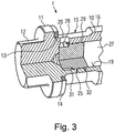
- the tensioning device 1 comprises a housing 10, which is designed as a turned / milled part.
- the housing 10 is divided into a head area and a Einschraub Scheme.
- the head portion has a abutment flange 11 and towards the end of a hexagonal projection 12, on which a tool for screwing the housing 10 can attack.
- a sealing seat 13 is provided, on which a rectangular cross-section annular seal 14 is seated.
- a cylindrical, forwardly open receiving bore 19 is formed, in which the clamping piston 9 is inserted substantially accurate fit and can reciprocate. Between the receiving bore 19 and the supply annular groove 15, a radially extending supply bore 20 is provided.
- the clamping piston 9 has an impression surface 21, in which a vent opening 22 is coaxially inserted. Except for the front region of the clamping piston 9 is designed as a hollow cylinder and therefore provides a receiving space for additional, not shown, components.
- this is a filling body 38 (FIG. Fig. 7 ).
- the filler 38 has a mushroom shape with a mushroom-shaped head 39 and a cylindrical extension 40 arranged thereon.
- a compression spring 42 (FIG. Fig. 6 ), which is supported at the front end on the back of the head of the filling body 38, wherein the cylindrical extension 40 is arranged in the interior of the compression spring 42 is.
- the tensioning piston 9 further has a receiving groove 24 for a sealing ring, so that there is essentially no leakage flow between the tensioning piston 9 and the receiving bore 19 of the housing 10.
- the filler 38 and the compression spring 42 are not in the the sake of clarity Fig. 2 and 3 drawn.
- a cylindrical supply insert 25 At the bottom of the receiving bore 19 is a cylindrical supply insert 25.
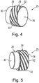
- a first embodiment of this supply insert 25 is based on the 4 and 5 even better to recognize.
- the supply insert 25 is made of a material that is softer than the material of the clamping piston 9.
- the clamping piston 9 is primarily made of steel.
- the supply insert 25 may be made of brass, aluminum or a plastic material. As a result, a certain impact protection for the tensioning piston 9 is also given to the supply insert 25. Depending on the combination of materials, this also leads to considerable noise reduction.
- the compression spring, not shown, then supported on the end face 26 of the supply insert 25. Between the supply insert 25 and the clamping piston 9, a pressure chamber 27 is formed.
- the compression spring, not shown, and the filling body, not shown, ensure a suitable reduction of the pressure chamber volume.
- the supply insert 25 has a first section 28 and a larger diameter second section 29.
- the end face 30 of the first section abuts against the bottom of the receiving bore 19.
- a flow gap is formed into which the supply bore 20 opens.
- the cylindrical second portion 29 is fitted accurately into the receiving bore 19 and provided on its peripheral surface with a total of ten helically extending damping channels 32 in the form of damping grooves.
- the damping channels 32 have in the present case a trapezoidal cross-section.
- the damping channels 32 further have a depth which is substantially less than the gradation between the first portion 28 and the second portion 29. All damping channels 32 are provided with the same pitch.
- the regions 33 between the damping channels 32 are sealed against the inner wall of the receiving bore 19.
- the supply insert 25 may be pressed into the receiving bore 19.
- This embodiment comes without check valve for supplying hydraulic fluid into the pressure chamber 27. All hydraulic fluid must pass through the damping channels 32 in the Flow in pressure chamber 27.
- the damping channels 32 are in direct flow communication with the flow gap 31.
- the shape of the damping channels 32 has a significant influence on the damping behavior of the clamping device 1.
- Examples include the cross-sectional shape of the damping channels, the dimensions of the damping channels, the number of damping channels and the course along the peripheral surface of the supply insert 25th
- the piston stroke frequency was chosen as the basis because this most closely reflects the dynamic behavior of the tensioning device 1.
- a consideration on the basis of the pressure in the pressure chamber or the speed of the internal combustion engine would be possible;
- the dynamic behavior can best be represented by means of the piston stroke frequency, because in this way the vibration state of the timing chain and thus the state that is actually to be damped are taken into account.
- the inflowing amount of hydraulic fluid is over 99% by means of the damping grooves 32 and thus via the supply insert 25.
- the small remaining share is due to the storage capacity the minimum existing gap between the clamping piston 9 and the receiving bore 19th
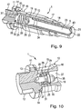
- the supply insert 25 is additionally formed on its end face 26 with a receiving seat 34 in which a check valve 35 is received.
- the structure and operation of the check valve 35 are known in the art, which is why this will not be explained here.
- a ball check valve is used with a valve ball biased by a spring.
- the check valve 35 allows the inflow of hydraulic fluid into the pressure chamber 27 and should prevent as far as possible an outflow from the pressure chamber 27. So that inflow via the supply insert 25 and the check valve 35 is possible, the supply insert 25 still has a central inlet bore 36 and radial inflow channels 37 on its end face 30, which connect the central inflow bore 36 with the flow gap 31.
- Fig. 13 is the flow distribution of the outflow shown on the basis of the diagram at these Kolbenhubfrequenzen.
- the main part of the discharge flow takes place again via the damping grooves 32 of the supply insert 25.
- the tensioning device tested exhibits a similar distribution at a piston stroke frequency of 50 Hz, as it already existed in the preceding embodiment.
- the values for the distribution of effluent flow in the test were as follows: Stroke rate RSV VE EB LSP [Hz] [%] [%] [%] [%] 200 12.7 70.9 15.8 0.5 100 2.3 75.0 22.1 0.6 50 0.0 64.7 34.7 0.6 medium: 5.0 70.2 24.2 0.6
- the abbreviation RSV stands for the check valve 35.
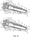
- a clamping device series is shown. These are again chain tensioners, as in the first embodiment.
- the upper clamping device 1.1. is identical to the clamping device Fig. 2 designed.
- the clamping device 1.2 shown below is also designed identical, with the exception of Supply use 25.2. In this supply insert 25.2, only the number of damping channels 32.2 has been reduced to the number 5. In this way, the lower tensioning device 1 acquires a much harder damping behavior, because less hydraulic fluid can be forced out of the pressure chamber 27 at one time.
- Fig. 14 shows a tensioner series based on the second embodiment. Again, only the number of damping channels 32.1 and 32.2 is different, while otherwise all components of the two clamping devices 1.1 and 1.2 shown are the same.
- the Fig. 17 schematically shows a first chain drive 2.1 (shown above) and a second chain drive 2.2 (shown below). These two chain drives differ solely and solely in that the tensioning device 1.1 at the top of the chain drive Fig. 15 or 14 and in the lower chain drive 2.2, the jig 1.2 off Fig. 15 or 16 are used. As a result, a chain drive series is generated which differs only by the use of different tensioning devices 1. However, it is also possible that within this series in addition to the different jigs 1.1 and 1.2 also different other elements can be used. Overall, however, a cost saving can be achieved due to the reduced number of parts.
Landscapes
- Engineering & Computer Science (AREA)
- General Engineering & Computer Science (AREA)
- Mechanical Engineering (AREA)
- Devices For Conveying Motion By Means Of Endless Flexible Members (AREA)
Claims (14)
- Dispositif tendeur (1) pour un moyen d'entrainement flexible tel qu'une chaine (5) ou une courroie, comprenant un corps (10), un piston tendeur (9) guidé de manière coulissante dans le corps (10), une chambre de pression (27) pour du fluide hydraulique, qui est formée entre le corps (10) et le piston tendeur (9), une amenée de fluide agencée dans le corps (10) et destinée à alimenter la chambre de pression (27) en fluide hydraulique, un dispositif d'amortissement en liaison fluidique avec la chambre de pression (27) et amortissant le mouvement de rentrée du piston tendeur (9), et un dispositif de purge d'air en liaison fluidique avec la chambre de pression (27),
dispositif tendeur
dans lequel le dispositif d'amortissement comprend au moins un canal d'amortissement (32), ouvert dans les deux directions d'écoulement, en tant que partie intégrante de l'amenée de fluide de façon telle, qu'en fonctionnement, au moins une partie de l'écoulement d'alimentation peut être envoyée dans la chambre de pression (27) à travers ledit au moins un canal d'amortissement (32), et le dispositif d'amortissement et le dispositif de purge d'air sont couplés sur le plan de la technique des fluides de manière telle qu'un écoulement d'évacuation de la chambre de pression (27) s'effectue de manière combinée par l'intermédiaire du dispositif d'amortissement et du dispositif de purge d'air, et l'écoulement d'alimentation s'effectue sensiblement de façon indépendante du dispositif de purge d'air, et
dans lequel l'amenée de fluide comprend un insert d'alimentation (25), qui est inséré de manière parfaitement ajustée dans le corps (10),
caractérisé en ce que ledit au moins un canal d'amortissement (32) est formé entre l'insert d'alimentation (25) et le corps (10). - Dispositif tendeur (1) selon la revendication 1, caractérisé en ce que le corps (10) présente un alésage d'accueil (19) dans lequel est logé de manière coulissante, le piston tendeur (9), et dans le fond de l'alésage d'accueil (19) est inséré de manière parfaitement ajustée, l'insert d'alimentation (25), et ledit au moins un canal d'amortissement (32) est formé entre la surface extérieure de l'insert d'alimentation (25) et la surface intérieure de l'alésage d'accueil (19) .
- Dispositif tendeur (1) selon la revendication 1 ou la revendication 2, caractérisé en ce que l'insert d'alimentation (25) présente un premier tronçon (28) et un deuxième tronçon (29) de circonférence plus grande, ledit au moins un canal d'amortissement (32) est formé dans ledit deuxième tronçon (29), et entre le premier tronçon (28) et le corps (10) est formé un interstice d'écoulement (31), qui fait partie de l'amenée de fluide.
- Dispositif tendeur (1) selon la revendication 3, caractérisé en ce que le corps (10) comporte un alésage d'alimentation (20) pouvant être raccordé à une alimentation en huile externe, en tant que partie intégrante de l'amenée de fluide, qui débouche dans l'interstice d'écoulement (31) entre le corps (10) et l'insert d'alimentation (25).
- Dispositif tendeur (1) selon l'une des revendications 1 à 4, caractérisé en ce que ledit au moins un canal d'amortissement (32) s'étend de manière périphérique, en hélice, sur la périphérie de l'insert d'alimentation (25).
- Dispositif tendeur (1) selon l'une des revendications 1 à 5, caractérisé en ce que sur l'insert d'alimentation (25) sont prévus au moins deux canaux d'amortissement (32), et les zones entre les canaux d'amortissement (32) s'appuient sensiblement de manière étanche contre le corps (10).
- Dispositif tendeur (1) selon l'une des revendications 1 à 6, caractérisé en ce que l'amenée de fluide comporte une valve antiretour (35) montée hydrauliquement en parallèle au canal d'amortissement (32) .
- Dispositif tendeur (1) selon la revendication 7, caractérisé en ce que la résistance à l'écoulement dudit au moins un canal d'amortissement (32) et la résistance à l'écoulement de la valve antiretour (35) dans la direction d'ouverture, sont adaptées mutuellement l'une à l'autre de manière telle, qu'au moins dans une plage de fréquence du piston tendeur de 50 - 200 Hz, plus de 90%, de préférence plus de 94%, de l'écoulement d'alimentation peut être amené à la chambre de pression (27) par l'intermédiaire de la valve antiretour (35).
- Dispositif tendeur (1) selon l'une des revendications 1 à 8, caractérisé en ce que résistance à l'écoulement dudit au moins un canal d'amortissement (32) et la résistance à l'écoulement du dispositif de purge d'air, sont adaptées mutuellement l'une à l'autre de manière telle, qu'au moins dans une plage de fréquence du piston tendeur de 50 - 200 Hz, au plus 45%, de préférence au plus 35%, de l'écoulement d'évacuation peut évacué de la chambre de pression (27) par l'intermédiaire du dispositif de purge d'air.
- Dispositif tendeur (1) selon l'une des revendications 1 à 9, caractérisé en ce que l'insert d'alimentation (25) est réalisé en un matériau plus tendre que le matériau du piston tendeur (9).
- Dispositif tendeur (1) selon l'une des revendications précédentes, caractérisé en ce qu'entre le piston tendeur (9) et l'alésage d'accueil (19) dans le corps (10), est agencé un joint d'étanchéité glissant.
- Série de dispositifs tendeurs, comprenant au moins un premier et au moins un deuxième dispositif tendeur (1.1; 1.2) selon l'une des revendications 1 à 11, caractérisée en ce que le premier et le deuxième dispositif tendeur (1.1; 1.2) comportent un alésage de corps (19) destiné à accueillir le piston tendeur (9), et un piston tendeur (9), chacun respectivement d'une grandeur en diamètre identique, standardisée, et le dispositif d'amortissement dudit au moins un premier dispositif tendeur (1.1) se différencie, quant à sa caractéristique d'amortissement, du dispositif d'amortissement dudit au moins un deuxième dispositif tendeur (1.2), les caractéristiques d'amortissement différentes étant obtenues au moyen d'inserts d'alimentation (25) dimensionnés et/ou configurés de manière différente.
- Transmission d'entrainement à enroulement comprenant un moyen d'entrainement flexible tel qu'une chaine (5) ou une courroie, au moins deux roues de transmission (3, 4.1, 4.2) en liaison interactive avec le moyen d'entrainement, et un dispositif tendeur (1) selon l'une des revendications 1 à 11.
- Série de transmissions d'entrainement à enroulement comprenant au moins une première transmission d'entrainement à enroulement (2.1) et au moins une deuxième transmission d'entrainement à enroulement (2.2), la première transmission d'entrainement à enroulement (2.1) comportant un premier dispositif tendeur (1.1) d'une série de dispositifs tendeurs selon la revendication 12, et la deuxième transmission d'entrainement à enroulement (2.2) comportant un deuxième dispositif tendeur (1.2) d'une série de dispositifs tendeurs selon la revendication 12, qui présente une caractéristique d'amortissement différente.
Applications Claiming Priority (1)
| Application Number | Priority Date | Filing Date | Title |
|---|---|---|---|
| DE102011122185A DE102011122185A1 (de) | 2011-12-23 | 2011-12-23 | Spannvorrichtung mit Dämpfungskanal in der Fluidzuführung |
Publications (2)
| Publication Number | Publication Date |
|---|---|
| EP2607748A1 EP2607748A1 (fr) | 2013-06-26 |
| EP2607748B1 true EP2607748B1 (fr) | 2019-07-10 |
Family
ID=46275657
Family Applications (1)
| Application Number | Title | Priority Date | Filing Date |
|---|---|---|---|
| EP12003979.7A Active EP2607748B1 (fr) | 2011-12-23 | 2012-05-22 | Dispositif de serrage avec canal d'amortissement dans l'introduction de liquide |
Country Status (3)
| Country | Link |
|---|---|
| US (1) | US9080643B2 (fr) |
| EP (1) | EP2607748B1 (fr) |
| DE (1) | DE102011122185A1 (fr) |
Families Citing this family (6)
| Publication number | Priority date | Publication date | Assignee | Title |
|---|---|---|---|---|
| JP5913040B2 (ja) * | 2012-10-09 | 2016-04-27 | 株式会社椿本チエイン | チェーンテンショナ |
| US10400870B2 (en) * | 2014-10-29 | 2019-09-03 | Borgwarner Inc. | Valvular paths |
| DE112015004282T5 (de) * | 2014-10-29 | 2017-06-22 | Borgwarner Inc. | Wirbelkanal |
| US10738861B2 (en) * | 2016-12-20 | 2020-08-11 | Borgwarner Inc. | Control of hydraulic tensioner tuning using hole size in piston nose |
| DE102017103534A1 (de) * | 2017-02-21 | 2018-08-23 | Iwis Motorsysteme Gmbh & Co. Kg | Ventileinheit mit Trägerplatte und Ventilkörper |
| JP7007575B2 (ja) * | 2018-02-21 | 2022-01-24 | 株式会社椿本チエイン | テンショナ |
Citations (1)
| Publication number | Priority date | Publication date | Assignee | Title |
|---|---|---|---|---|
| EP2458246A1 (fr) * | 2010-11-29 | 2012-05-30 | iwis motorsysteme GmbH & Co. KG | Dispositif de serrage doté d'un dispositif d'évaporation comprenant un volume de réception minimal |
Family Cites Families (6)
| Publication number | Priority date | Publication date | Assignee | Title |
|---|---|---|---|---|
| DE4311056C1 (de) * | 1993-04-03 | 1994-07-07 | Bayerische Motoren Werke Ag | Bewegungsdämpfer einer Spannvorrichtung |
| US5643117A (en) | 1995-12-08 | 1997-07-01 | Borg-Warner Automotive, Inc. | Hydraulic tensioner with check valve vent |
| JP3642527B1 (ja) | 2004-05-31 | 2005-04-27 | 株式会社椿本チエイン | 油圧式テンショナ |
| DE202007002456U1 (de) | 2007-02-20 | 2008-07-03 | Iwis Motorsysteme Gmbh & Co. Kg | Spannvorrichtung mit dynamischen Entlüftungsventil |
| JP2010121748A (ja) * | 2008-11-21 | 2010-06-03 | Ntn Corp | チェーンテンショナ |
| DE202009003615U1 (de) * | 2009-03-13 | 2010-07-22 | Iwis Motorsysteme Gmbh & Co. Kg | Kettenspannsystem mit spritzgegossenem Aufdrückstopfen |
-
2011
- 2011-12-23 DE DE102011122185A patent/DE102011122185A1/de not_active Withdrawn
-
2012
- 2012-05-22 EP EP12003979.7A patent/EP2607748B1/fr active Active
- 2012-12-21 US US13/725,297 patent/US9080643B2/en not_active Expired - Fee Related
Patent Citations (1)
| Publication number | Priority date | Publication date | Assignee | Title |
|---|---|---|---|---|
| EP2458246A1 (fr) * | 2010-11-29 | 2012-05-30 | iwis motorsysteme GmbH & Co. KG | Dispositif de serrage doté d'un dispositif d'évaporation comprenant un volume de réception minimal |
Also Published As
| Publication number | Publication date |
|---|---|
| US20130178317A1 (en) | 2013-07-11 |
| EP2607748A1 (fr) | 2013-06-26 |
| US9080643B2 (en) | 2015-07-14 |
| DE102011122185A1 (de) | 2013-06-27 |
Similar Documents
| Publication | Publication Date | Title |
|---|---|---|
| DE102012103300B4 (de) | Schwenkmotorversteller mit einem Zentralventil | |
| DE102015206081B4 (de) | Kettenspanneinrichtung | |
| DE102014200065B4 (de) | Kettenspanner | |
| DE102016221888B4 (de) | Kettenspanneinrichtung | |
| DE102016221898B4 (de) | Kettenspanneinrichtung | |
| DE102013220021A1 (de) | Kettenspanner | |
| EP2607748A1 (fr) | Dispositif de serrage avec canal d'amortissement dans l'introduction de liquide | |
| DE102016221892B4 (de) | Kettenspanneinrichtung | |
| EP2458246B1 (fr) | Dispositif de serrage doté d'un dispositif d'évaporation comprenant un volume de réception minimal | |
| DE102008059212A1 (de) | Spanner für einen endlosen Übertragungsstrang | |
| AT519290B1 (de) | Längenverstellbare Pleuelstange mit einer Zylinder-Kolben-Einheit mit Ölfilter | |
| WO2010040511A1 (fr) | Ensemble soupape de limitation de pression et soupape anticavitation | |
| AT519305B1 (de) | Längenverstellbare Pleuelstange mit einer Zylinder-Kolben-Einheit mit mehreren Kolbendichtungen | |
| DE19819995A1 (de) | Vorrichtung zur hydraulischen Drehwinkelverstellung einer Welle zu einem Antriebsrad | |
| DE102011056264B4 (de) | Hydraulikventil | |
| EP0509077B1 (fr) | Pompe a pistons, notamment pompe a pistons radiaux | |
| DE102007051407A1 (de) | Ventil und Herstellungsverfahren für ein Ventil | |
| AT519297A2 (de) | Pleuelstange mit gekapselter Baugruppe zur Längenverstellung | |
| DE102011000591B4 (de) | Zentralventil für einen Schwenkmotorversteller | |
| DE102010013777A1 (de) | Zentralventil | |
| AT519294B1 (de) | Längenverstellbare Pleuelstange mit einer Zylinder-Kolben-Einheit mit Zylinderhülse | |
| DE102009022868B4 (de) | Flügelzellennockenwellenversteller | |
| EP2423536B1 (fr) | Dispositif de serrage hydraulique doté d'un stockage temporaire | |
| DE10103014A1 (de) | Radialkolbenpumpe | |
| AT500629B1 (de) | Zahnradpumpe |
Legal Events
| Date | Code | Title | Description |
|---|---|---|---|
| AK | Designated contracting states |
Kind code of ref document: A1 Designated state(s): AL AT BE BG CH CY CZ DE DK EE ES FI FR GB GR HR HU IE IS IT LI LT LU LV MC MK MT NL NO PL PT RO RS SE SI SK SM TR |
|
| AX | Request for extension of the european patent |
Extension state: BA ME |
|
| PUAI | Public reference made under article 153(3) epc to a published international application that has entered the european phase |
Free format text: ORIGINAL CODE: 0009012 |
|
| 17P | Request for examination filed |
Effective date: 20130719 |
|
| RBV | Designated contracting states (corrected) |
Designated state(s): AL AT BE BG CH CY CZ DE DK EE ES FI FR GB GR HR HU IE IS IT LI LT LU LV MC MK MT NL NO PL PT RO RS SE SI SK SM TR |
|
| 17Q | First examination report despatched |
Effective date: 20140814 |
|
| STAA | Information on the status of an ep patent application or granted ep patent |
Free format text: STATUS: EXAMINATION IS IN PROGRESS |
|
| GRAP | Despatch of communication of intention to grant a patent |
Free format text: ORIGINAL CODE: EPIDOSNIGR1 |
|
| STAA | Information on the status of an ep patent application or granted ep patent |
Free format text: STATUS: GRANT OF PATENT IS INTENDED |
|
| INTG | Intention to grant announced |
Effective date: 20190128 |
|
| GRAS | Grant fee paid |
Free format text: ORIGINAL CODE: EPIDOSNIGR3 |
|
| GRAA | (expected) grant |
Free format text: ORIGINAL CODE: 0009210 |
|
| STAA | Information on the status of an ep patent application or granted ep patent |
Free format text: STATUS: THE PATENT HAS BEEN GRANTED |
|
| AK | Designated contracting states |
Kind code of ref document: B1 Designated state(s): AL AT BE BG CH CY CZ DE DK EE ES FI FR GB GR HR HU IE IS IT LI LT LU LV MC MK MT NL NO PL PT RO RS SE SI SK SM TR |
|
| REG | Reference to a national code |
Ref country code: GB Ref legal event code: FG4D Free format text: NOT ENGLISH |
|
| REG | Reference to a national code |
Ref country code: CH Ref legal event code: EP Ref country code: AT Ref legal event code: REF Ref document number: 1153909 Country of ref document: AT Kind code of ref document: T Effective date: 20190715 |
|
| REG | Reference to a national code |
Ref country code: DE Ref legal event code: R096 Ref document number: 502012015007 Country of ref document: DE |
|
| REG | Reference to a national code |
Ref country code: IE Ref legal event code: FG4D Free format text: LANGUAGE OF EP DOCUMENT: GERMAN |
|
| REG | Reference to a national code |
Ref country code: NL Ref legal event code: MP Effective date: 20190710 |
|
| REG | Reference to a national code |
Ref country code: LT Ref legal event code: MG4D |
|
| PG25 | Lapsed in a contracting state [announced via postgrant information from national office to epo] |
Ref country code: NO Free format text: LAPSE BECAUSE OF FAILURE TO SUBMIT A TRANSLATION OF THE DESCRIPTION OR TO PAY THE FEE WITHIN THE PRESCRIBED TIME-LIMIT Effective date: 20191010 Ref country code: NL Free format text: LAPSE BECAUSE OF FAILURE TO SUBMIT A TRANSLATION OF THE DESCRIPTION OR TO PAY THE FEE WITHIN THE PRESCRIBED TIME-LIMIT Effective date: 20190710 Ref country code: PT Free format text: LAPSE BECAUSE OF FAILURE TO SUBMIT A TRANSLATION OF THE DESCRIPTION OR TO PAY THE FEE WITHIN THE PRESCRIBED TIME-LIMIT Effective date: 20191111 Ref country code: BG Free format text: LAPSE BECAUSE OF FAILURE TO SUBMIT A TRANSLATION OF THE DESCRIPTION OR TO PAY THE FEE WITHIN THE PRESCRIBED TIME-LIMIT Effective date: 20191010 Ref country code: LT Free format text: LAPSE BECAUSE OF FAILURE TO SUBMIT A TRANSLATION OF THE DESCRIPTION OR TO PAY THE FEE WITHIN THE PRESCRIBED TIME-LIMIT Effective date: 20190710 Ref country code: FI Free format text: LAPSE BECAUSE OF FAILURE TO SUBMIT A TRANSLATION OF THE DESCRIPTION OR TO PAY THE FEE WITHIN THE PRESCRIBED TIME-LIMIT Effective date: 20190710 Ref country code: SE Free format text: LAPSE BECAUSE OF FAILURE TO SUBMIT A TRANSLATION OF THE DESCRIPTION OR TO PAY THE FEE WITHIN THE PRESCRIBED TIME-LIMIT Effective date: 20190710 Ref country code: HR Free format text: LAPSE BECAUSE OF FAILURE TO SUBMIT A TRANSLATION OF THE DESCRIPTION OR TO PAY THE FEE WITHIN THE PRESCRIBED TIME-LIMIT Effective date: 20190710 |
|
| PG25 | Lapsed in a contracting state [announced via postgrant information from national office to epo] |
Ref country code: AL Free format text: LAPSE BECAUSE OF FAILURE TO SUBMIT A TRANSLATION OF THE DESCRIPTION OR TO PAY THE FEE WITHIN THE PRESCRIBED TIME-LIMIT Effective date: 20190710 Ref country code: RS Free format text: LAPSE BECAUSE OF FAILURE TO SUBMIT A TRANSLATION OF THE DESCRIPTION OR TO PAY THE FEE WITHIN THE PRESCRIBED TIME-LIMIT Effective date: 20190710 Ref country code: IS Free format text: LAPSE BECAUSE OF FAILURE TO SUBMIT A TRANSLATION OF THE DESCRIPTION OR TO PAY THE FEE WITHIN THE PRESCRIBED TIME-LIMIT Effective date: 20191110 Ref country code: GR Free format text: LAPSE BECAUSE OF FAILURE TO SUBMIT A TRANSLATION OF THE DESCRIPTION OR TO PAY THE FEE WITHIN THE PRESCRIBED TIME-LIMIT Effective date: 20191011 Ref country code: LV Free format text: LAPSE BECAUSE OF FAILURE TO SUBMIT A TRANSLATION OF THE DESCRIPTION OR TO PAY THE FEE WITHIN THE PRESCRIBED TIME-LIMIT Effective date: 20190710 Ref country code: ES Free format text: LAPSE BECAUSE OF FAILURE TO SUBMIT A TRANSLATION OF THE DESCRIPTION OR TO PAY THE FEE WITHIN THE PRESCRIBED TIME-LIMIT Effective date: 20190710 |
|
| PG25 | Lapsed in a contracting state [announced via postgrant information from national office to epo] |
Ref country code: TR Free format text: LAPSE BECAUSE OF FAILURE TO SUBMIT A TRANSLATION OF THE DESCRIPTION OR TO PAY THE FEE WITHIN THE PRESCRIBED TIME-LIMIT Effective date: 20190710 |
|
| PG25 | Lapsed in a contracting state [announced via postgrant information from national office to epo] |
Ref country code: IT Free format text: LAPSE BECAUSE OF FAILURE TO SUBMIT A TRANSLATION OF THE DESCRIPTION OR TO PAY THE FEE WITHIN THE PRESCRIBED TIME-LIMIT Effective date: 20190710 Ref country code: PL Free format text: LAPSE BECAUSE OF FAILURE TO SUBMIT A TRANSLATION OF THE DESCRIPTION OR TO PAY THE FEE WITHIN THE PRESCRIBED TIME-LIMIT Effective date: 20190710 Ref country code: DK Free format text: LAPSE BECAUSE OF FAILURE TO SUBMIT A TRANSLATION OF THE DESCRIPTION OR TO PAY THE FEE WITHIN THE PRESCRIBED TIME-LIMIT Effective date: 20190710 Ref country code: EE Free format text: LAPSE BECAUSE OF FAILURE TO SUBMIT A TRANSLATION OF THE DESCRIPTION OR TO PAY THE FEE WITHIN THE PRESCRIBED TIME-LIMIT Effective date: 20190710 Ref country code: RO Free format text: LAPSE BECAUSE OF FAILURE TO SUBMIT A TRANSLATION OF THE DESCRIPTION OR TO PAY THE FEE WITHIN THE PRESCRIBED TIME-LIMIT Effective date: 20190710 |
|
| PG25 | Lapsed in a contracting state [announced via postgrant information from national office to epo] |
Ref country code: CZ Free format text: LAPSE BECAUSE OF FAILURE TO SUBMIT A TRANSLATION OF THE DESCRIPTION OR TO PAY THE FEE WITHIN THE PRESCRIBED TIME-LIMIT Effective date: 20190710 Ref country code: SM Free format text: LAPSE BECAUSE OF FAILURE TO SUBMIT A TRANSLATION OF THE DESCRIPTION OR TO PAY THE FEE WITHIN THE PRESCRIBED TIME-LIMIT Effective date: 20190710 Ref country code: SK Free format text: LAPSE BECAUSE OF FAILURE TO SUBMIT A TRANSLATION OF THE DESCRIPTION OR TO PAY THE FEE WITHIN THE PRESCRIBED TIME-LIMIT Effective date: 20190710 Ref country code: IS Free format text: LAPSE BECAUSE OF FAILURE TO SUBMIT A TRANSLATION OF THE DESCRIPTION OR TO PAY THE FEE WITHIN THE PRESCRIBED TIME-LIMIT Effective date: 20200224 |
|
| REG | Reference to a national code |
Ref country code: DE Ref legal event code: R097 Ref document number: 502012015007 Country of ref document: DE |
|
| PLBE | No opposition filed within time limit |
Free format text: ORIGINAL CODE: 0009261 |
|
| STAA | Information on the status of an ep patent application or granted ep patent |
Free format text: STATUS: NO OPPOSITION FILED WITHIN TIME LIMIT |
|
| PG2D | Information on lapse in contracting state deleted |
Ref country code: IS |
|
| 26N | No opposition filed |
Effective date: 20200603 |
|
| PG25 | Lapsed in a contracting state [announced via postgrant information from national office to epo] |
Ref country code: SI Free format text: LAPSE BECAUSE OF FAILURE TO SUBMIT A TRANSLATION OF THE DESCRIPTION OR TO PAY THE FEE WITHIN THE PRESCRIBED TIME-LIMIT Effective date: 20190710 |
|
| PG25 | Lapsed in a contracting state [announced via postgrant information from national office to epo] |
Ref country code: CH Free format text: LAPSE BECAUSE OF NON-PAYMENT OF DUE FEES Effective date: 20200531 Ref country code: LI Free format text: LAPSE BECAUSE OF NON-PAYMENT OF DUE FEES Effective date: 20200531 Ref country code: MC Free format text: LAPSE BECAUSE OF FAILURE TO SUBMIT A TRANSLATION OF THE DESCRIPTION OR TO PAY THE FEE WITHIN THE PRESCRIBED TIME-LIMIT Effective date: 20190710 |
|
| REG | Reference to a national code |
Ref country code: BE Ref legal event code: MM Effective date: 20200531 |
|
| GBPC | Gb: european patent ceased through non-payment of renewal fee |
Effective date: 20200522 |
|
| PG25 | Lapsed in a contracting state [announced via postgrant information from national office to epo] |
Ref country code: LU Free format text: LAPSE BECAUSE OF NON-PAYMENT OF DUE FEES Effective date: 20200522 |
|
| PG25 | Lapsed in a contracting state [announced via postgrant information from national office to epo] |
Ref country code: GB Free format text: LAPSE BECAUSE OF NON-PAYMENT OF DUE FEES Effective date: 20200522 Ref country code: FR Free format text: LAPSE BECAUSE OF NON-PAYMENT OF DUE FEES Effective date: 20200531 Ref country code: IE Free format text: LAPSE BECAUSE OF NON-PAYMENT OF DUE FEES Effective date: 20200522 |
|
| PG25 | Lapsed in a contracting state [announced via postgrant information from national office to epo] |
Ref country code: BE Free format text: LAPSE BECAUSE OF NON-PAYMENT OF DUE FEES Effective date: 20200531 |
|
| REG | Reference to a national code |
Ref country code: AT Ref legal event code: MM01 Ref document number: 1153909 Country of ref document: AT Kind code of ref document: T Effective date: 20200522 |
|
| PGFP | Annual fee paid to national office [announced via postgrant information from national office to epo] |
Ref country code: DE Payment date: 20210525 Year of fee payment: 10 |
|
| PG25 | Lapsed in a contracting state [announced via postgrant information from national office to epo] |
Ref country code: AT Free format text: LAPSE BECAUSE OF NON-PAYMENT OF DUE FEES Effective date: 20200522 |
|
| PG25 | Lapsed in a contracting state [announced via postgrant information from national office to epo] |
Ref country code: MT Free format text: LAPSE BECAUSE OF FAILURE TO SUBMIT A TRANSLATION OF THE DESCRIPTION OR TO PAY THE FEE WITHIN THE PRESCRIBED TIME-LIMIT Effective date: 20190710 Ref country code: CY Free format text: LAPSE BECAUSE OF FAILURE TO SUBMIT A TRANSLATION OF THE DESCRIPTION OR TO PAY THE FEE WITHIN THE PRESCRIBED TIME-LIMIT Effective date: 20190710 |
|
| PG25 | Lapsed in a contracting state [announced via postgrant information from national office to epo] |
Ref country code: MK Free format text: LAPSE BECAUSE OF FAILURE TO SUBMIT A TRANSLATION OF THE DESCRIPTION OR TO PAY THE FEE WITHIN THE PRESCRIBED TIME-LIMIT Effective date: 20190710 |
|
| REG | Reference to a national code |
Ref country code: DE Ref legal event code: R119 Ref document number: 502012015007 Country of ref document: DE |
|
| PG25 | Lapsed in a contracting state [announced via postgrant information from national office to epo] |
Ref country code: DE Free format text: LAPSE BECAUSE OF NON-PAYMENT OF DUE FEES Effective date: 20221201 |