EP2607797A2 - Four ventilé, en particulier four ventilé domestique - Google Patents
Four ventilé, en particulier four ventilé domestique Download PDFInfo
- Publication number
- EP2607797A2 EP2607797A2 EP12199111.1A EP12199111A EP2607797A2 EP 2607797 A2 EP2607797 A2 EP 2607797A2 EP 12199111 A EP12199111 A EP 12199111A EP 2607797 A2 EP2607797 A2 EP 2607797A2
- Authority
- EP
- European Patent Office
- Prior art keywords
- muffle
- fan
- cavity
- oven
- compartment
- Prior art date
- Legal status (The legal status is an assumption and is not a legal conclusion. Google has not performed a legal analysis and makes no representation as to the accuracy of the status listed.)
- Granted
Links
Images


Classifications
-
- F—MECHANICAL ENGINEERING; LIGHTING; HEATING; WEAPONS; BLASTING
- F24—HEATING; RANGES; VENTILATING
- F24C—DOMESTIC STOVES OR RANGES ; DETAILS OF DOMESTIC STOVES OR RANGES, OF GENERAL APPLICATION
- F24C15/00—Details
- F24C15/32—Arrangements of ducts for hot gases, e.g. in or around baking ovens
- F24C15/322—Arrangements of ducts for hot gases, e.g. in or around baking ovens with forced circulation
- F24C15/325—Arrangements of ducts for hot gases, e.g. in or around baking ovens with forced circulation electrically-heated
Definitions
- the present invention relates to an oven of the ventilated type, in particular for domestic use, according to the preamble of claim 1.
- the present invention is typically applicable to ventilated ovens, in particular for domestic use, of the type comprising a compartment for cooking food.
- ovens of the static type As is known, different types of ovens are currently available on the market; the most widespread ones include ovens of the static type and ovens of the ventilated type.
- An oven of the static type known in the art comprises:
- the front wall of an oven of the static type comprises a door which can be opened in order to place food to be cooked into the cooking compartment.
- an oven of the ventilated type additionally includes a fan associated with said heating means, the fan and the heating means being typically situated in a cavity associated with the back wall of the muffle.
- the ovens of the ventilated type known in the art suffer from the drawback that the air circulated by the fan and conveyed towards the cooking compartment of the muffle stagnates within said cavity; as a consequence, this inevitably leads to a reduced fluid-dynamic efficiency of the oven, and hence to a reduced efficiency of the food cooking process taking place in said cooking compartment.
- an oven of the ventilated type known in the art usually comprises:
- the fan sucks air into said cavity from the cooking compartment, in particular through said at least one passage obtained in the bulkhead that separates the cooking compartment from the cavity; in said cavity, the air gets heated through contact with the heating means; the air flow generated by the fan and heated is then reintroduced into the cooking compartment through said at least one opening obtained in the bulkhead.
- Ventilated ovens are somewhat advantageous over static ovens, the advantage mainly consisting of the fact that the air circulation caused by the fan's action ensures a better distribution of the hot air in the cooking compartment.
- ventilated ovens actually improve the distribution of the hot air flow, it has been observed in practice that said air distribution is often not uniform enough to ensure proper cooking of foods arranged together at different levels in the cooking compartment. As a matter of fact, it has been observed that, when several shelves or dripping pans are placed at different levels in the cooking compartment, the foods contained therein get cooked differently.
- the presence of at least one passage (for sucking air into said cavity from the cooking compartment) and at least one opening (for reintroducing into the cooking compartment the hot air flow generated by the fan) obtained in the bulkhead that separates the cavity from the cooking compartment does not allow for optimally feeding and distributing the hot air in the cooking compartment or adequately sucking in the air from said cooking compartment.
- the foods being cooked are mostly lapped by the return air flow, resulting in a loss of cooking efficiency due to the fact that the return flow has a lower energy content than the delivery flow.
- the present invention aims at solving these and other problems suffered by the ventilated ovens known in the art.
- reference numeral 1 designates as a whole an oven of the ventilated type, in particular for domestic use, according to the present invention.
- the oven 1 comprises a muffle 10 defining a cooking compartment 10V where food to be cooked is placed, said muffle 10 comprising a bottom wall or base 11, a top wall or ceiling 12, a back wall 13, a front wall 14 opposite to said back wall 13, and two mutually opposite side walls 15.
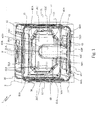
- the muffle 10 is preferably housed in a cabinet 2 of the oven 1, said cabinet 2 being represented by a dashed line in Figures 1 and 2 ; the space between the cabinet 2 and the muffle 10 may be at least partially filled with insulating material (not shown in the drawings).
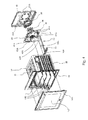
- a plurality of shelves 10R comprising, for example, extractable dripping pans or wire-racks, visible in simplified form in Fig. 3 and partially shown in Fig. 4 ), by means of which foods to be cooked can be arranged at different levels in the compartment 10V.
- the front wall 14 comprises a door 14S; as known in the art, the door 14S is hinged to the cabinet 2 and/or to the muffle 10, so as to switch the muffle 10 from a closed configuration (which configuration is typically used when cooking foods in the cooking compartment 10V) to an open configuration (which configuration is typically used when placing food to be cooked into the cooking compartment 10V), and vice versa.
- said door 14S comprises at least one transparent pane 14T, in particular made of glass; said at least one transparent pane 14T allows a user to look into the compartment 10V, in particular for the purpose of visually checking the cooking of the food in the compartment 10V.
- the oven 1 comprises heating means 20 (shown in Fig. 3 ) associated with the muffle 10 for heating air in said muffle 10 and causing said food to be cooked.
- the oven 1 also comprises a fan 30 for circulating air in said muffle 10, the fan 30 being situated in a cavity 40 associated with the back wall 13 of the muffle 10 via a bulkhead 41.
- the heating means 20 are associated with the fan 30 and are situated in said cavity 40; furthermore, said heating means 20 are preferably of the resistive type and comprise at least one electric resistor, in particular a circular one and/ or such as to surround said fan 30.
- the fan 30 is of the type that sucks in air axially and circulates it radially (in Fig. 3 the paths followed by the air in the compartment 10V of the muffle 10 are shown by means of dashed lines), and said heating means 20 (in particular consisting of an electric resistor) are substantially so realized as to surround the fan 30, so that they are lapped by all the air circulated by said fan 30, thus optimizing the heating thereof within said muffle 10.
- heating means 20 may be realized in a different manner and be placed in other positions in the muffle 10.
- the oven 1 also comprises auxiliary heating means (not shown in the drawings) associated with the ceiling 12 for irradiation cooking.
- auxiliary heating means (not shown in the drawings) associated with the ceiling 12 for irradiation cooking.
- the oven 1 according to the present invention further comprises:
- said at least one opening 51 comprises a plurality of openings 51 obtained at different levels in said bulkhead 41, so that an adequate air flow can reach every shelf 10R.
- said at least one passage 61 comprises a grid 61G adapted to divide the passage 61 into a plurality of holes; it is however clear that said at least one passage 61 may be so realized as to include no additional elements, thus having a single hole corresponding to said passage 61.
- the presence of the grid 61G is not necessary, since the fan 30 is not accessible to the user while the oven 1 is in operation.
- said return means 60 comprise a channel 62 having a first end 62A associated with said at least one passage 61 and a second end 62B situated in the proximity of the front wall 14, so as to draw air near the front wall 14 of the muffle 10 and convey it towards the fan 30 through said at least one passage 61.
- the channel 62 extends from the back wall 13 to proximate the front wall 14.
- the special provision of the channel 62 allows to properly take into account the fluid dynamics existing in the cooking compartment 10V and to ensure uniformity of air distribution in the compartment 10V in order to obtain a homogeneous cooking of the foods placed therein.
- the presence of the channel 62 allows to optimally feed and distribute hot air into the cooking compartment 10V, as well as to adequately draw air from said cooking compartment 10V, while also distributing the air flow delivered through said at least one opening 51 throughout the volume of the cooking compartment 10V.
- Said channel 62 is associated with at least one of said bottom wall 11, top wall 12 and two side walls 15; in particular, said channel 62 is associated with the bottom wall 11 of the muffle 10, in particular in such a way that said bottom wall 11 can also form the base of said channel 62.
- said channel 62 is at least partly secured to the bottom wall 11 through fastening means (not shown, since they are of a known type). Screws are advantageously used as fastening means in order to ensure internal access to said channel 62 for maintenance and/or service.
- said second end 62B of the channel 62 comprises at least one port 63 for sucking in air near the front wall 14.
- said at least one port 63 is placed on a ridge 63A of the second end 62B, said ridge 63A being raised relative to the second end 62B and to the bottom wall 11.
- This allows said at least one port 63 to suck in the air near the front wall 14 without being clogged by food residues or overflows (especially liquid ones) which may accumulate on said bottom wall 11; as a result, such a provision ensures the proper operation of the port 63 and of the entire channel 62.
- the channel 62 comprises:
- the channel 62 substantially has a "T" shape when viewed from above, in particular when viewed from above starting from the back wall 13 towards the front wall 14.
- the particular shape of the channel 62 allows the air contained in the cooking compartment 10V to be adequately sucked in; in particular, the shape of the second end 62B and the positioning of the plurality of ports 63 in the proximity of the front wall 14 allows to draw the air farthest from the fan 30, while at the same time scrubbing the entire transparent pane 14T to eliminate any condensate possibly formed thereon and to keep the temperature of said transparent pane 14T as even as possible, so as to reduce any tensions that might be generated on the transparent pane 14T, in particular when pyrolysis is taking place.
- the channel 62 comprises a section 62D that connects the first end 62A to the intermediate body 62C, in particular said section 62D being associated with the bulkhead 41 and extending substantially in a vertical direction in said compartment 10V.
- the section 62D is at least partially secured to the bulkhead 41 through fastening means (not shown, since they are of a known type, e.g. screws), so that said bulkhead 41 can constitute at least a part of the section 62D of the channel 62.
- the channel 62 substantially has a "laid-down L" shape, when viewed from the side (e.g. in the sectional view of Fig. 3 ).
- the channel 62 is made as two pieces connected together in the proximity of a curved section 62E, the first piece comprising the first end 62A and the section 62D, and the second piece comprising the second end 62B and the intermediate body 62C.
- the cavity 40 is obtained by associating the bulkhead 41 with the back wall 13.
- the oven 1 comprises portions of the bulkhead 41 and of the back wall 13 cooperating to form the cavity 40 and having smooth corners 13A, 41A and/or rounded edges to prevent the air circulated by the fan 30 and conveyed towards said at least one opening 51 from stagnating within the cavity 40, resulting in a loss of fluid-dynamic efficiency of the oven 1 and leading to a less efficient cooking process.
- Figures 1 and 4 show that the back wall 13 comprises first smooth corners 13A (visible in Fig. 4 ), and that the bulkhead 41 comprises respective second smooth corners 41A, said first corners 13A being coupled to the second corners 41A to form respective corners (not shown) of the cavity 40.
- Such a provision proves to be particularly advantageous because, by preventing air from stagnating within the cavity 40, it is possible to obtain an adequate air circulation in the cavity 40 and an optimal change of air in the cooking compartment 10V; as a consequence, the maximum air flow circulated by the fan 30 can be exploited for cooking food in the compartment 10V.
- the openings 51 are distributed over the bulkhead 41 as a function of the direction of rotation of the fan 30 and/or of the position of the shelves 10R in the compartment 10V of the muffle 10, particularly in such a way as to ensure that there is at least one opening 51 for each cooking level.
- the openings 51 are preferably rectangular in shape, and are obtained by means of shearing and bending operations.
- said openings 51 comprise:
- Said front openings 51B may be symmetrical relative to the plane P, or else such symmetry may be advantageously altered in a manner such that the front openings 51B on either side of the bulkhead 41 are closer to the centre of the bulkhead 41, depending on the direction of rotation of the fan 30. For example, if the fan 30 rotates clockwise when viewed from the door 14S, then said front openings 51B will be closer to the centre on the left side of the bulkhead 41; if the fan 30 rotates counterclockwise when viewed from the door 14S, then said front openings 51B will be closer to the centre on the right side of the bulkhead 41.
- the heating means 20 preferably comprise a circular electric resistor having a pitch comprised between 1.5 and 2 times its diameter.
- metal fins are fitted to the electric resistor to convey the air flow exiting the fan 30 and to distribute the heat generated by the resistor.
- the presence of the channel 62 allows to optimally feed and distribute the hot air into the cooking compartment 10V, as well as to adequately draw air from said cooking compartment 10V.
- the channel 62 prevents the air flow drawn into the cavity 40 from the cooking compartment 10V from interfering with the air flow fed into said cooking compartment 10V from the cavity 40, and vice versa; consequently, the absence of any interference between the air flow drawn from the compartment 10V and the air flow fed into said compartment 10V significantly improves the distribution of the hot air inside the muffle 10.
- a further advantage is that the particular realization of the channel 62 according to the present invention, i.e. the fact that it comprises a second end 62B situated in the proximity of the front wall 14 of the muffle 10, allows to draw air near said front wall 14 and to create a sort of a vacuum which can then be gradually filled with new heated air, fed into the compartment 10V by the fan 30.
- Such a realization of the channel 62 and the positioning of the plurality of ports 63 in the proximity of the front wall 14 allows to suck in the air farthest from the fan 30, while at the same time scrubbing the entire transparent pane 14T in order to eliminate any condensate possibly formed thereon. Furthermore, the fact that the ports 63 are situated on a ridge 63A of the second end 62B allows to suck in the air near the front wall 14 without running the risk that said ports 63 might get clogged by residues possibly accumulated in the cooking compartment 10V.
- a further advantage of the present invention is that the provision of smooth corners 13A, 41A and/or rounded edges on those portions of the bulkhead 41 and of the back wall 13 which cooperate to form the cavity 40 allows to prevent air from stagnating within the cavity 40; this is advantageous because it ensures adequate air recirculation in the cavity 40 and an optimal change of air inside the cooking compartment 10V, so that it can be exploited at best for food cooking.
- the air processed by the fan 30 is less noisy thanks to the provision of smooth corners 13A, 41A and/or rounded edges.
Landscapes
- Engineering & Computer Science (AREA)
- Chemical & Material Sciences (AREA)
- Combustion & Propulsion (AREA)
- Mechanical Engineering (AREA)
- General Engineering & Computer Science (AREA)
- Electric Stoves And Ranges (AREA)
Applications Claiming Priority (2)
| Application Number | Priority Date | Filing Date | Title |
|---|---|---|---|
| IT000149U ITTO20110149U1 (it) | 2011-12-22 | 2011-12-22 | Forno di tipo ventilato, in particolare ad uso domestico. |
| IT001195A ITTO20111195A1 (it) | 2011-12-22 | 2011-12-22 | Forno di tipo ventilato, in particolare ad uso domestico |
Publications (3)
| Publication Number | Publication Date |
|---|---|
| EP2607797A2 true EP2607797A2 (fr) | 2013-06-26 |
| EP2607797A3 EP2607797A3 (fr) | 2013-09-11 |
| EP2607797B1 EP2607797B1 (fr) | 2019-10-23 |
Family
ID=47358424
Family Applications (1)
| Application Number | Title | Priority Date | Filing Date |
|---|---|---|---|
| EP12199111.1A Active EP2607797B1 (fr) | 2011-12-22 | 2012-12-21 | Four ventilé, en particulier four ventilé domestique |
Country Status (1)
| Country | Link |
|---|---|
| EP (1) | EP2607797B1 (fr) |
Cited By (4)
| Publication number | Priority date | Publication date | Assignee | Title |
|---|---|---|---|---|
| WO2015092643A1 (fr) | 2013-12-17 | 2015-06-25 | Indesit Company S.P.A. | Four ventilé à chauffage direct |
| WO2015092640A1 (fr) | 2013-12-17 | 2015-06-25 | Indesit Company S.P.A. | Four à ventilateur de chauffe directe |
| WO2015092642A1 (fr) | 2013-12-17 | 2015-06-25 | Indesit Company S.P.A. | Four à ventilateur à chauffage direct |
| WO2016124789A3 (fr) * | 2015-02-06 | 2016-10-27 | Michael James Mcintyre | Appareil de cuisson et dispositif de distribution et de circulation d'air associé |
Family Cites Families (6)
| Publication number | Priority date | Publication date | Assignee | Title |
|---|---|---|---|---|
| JPS6321424A (ja) * | 1986-07-11 | 1988-01-29 | Toshiba Corp | 調理器 |
| US6060701A (en) * | 1997-05-27 | 2000-05-09 | Turbochef Technologies, Inc. | Compact quick-cooking convectional oven |
| US6376817B1 (en) * | 1998-10-09 | 2002-04-23 | Turbochef Technologies, Inc. | Compact quick-cooking oven |
| KR20060070910A (ko) * | 2004-12-21 | 2006-06-26 | 삼성전자주식회사 | 전기오븐 |
| KR100697022B1 (ko) * | 2005-04-11 | 2007-03-20 | 엘지전자 주식회사 | 조리기기의 컨벡션 챔버 |
| KR100735183B1 (ko) * | 2005-12-28 | 2007-07-03 | 엘지전자 주식회사 | 전기 오븐 |
-
2012
- 2012-12-21 EP EP12199111.1A patent/EP2607797B1/fr active Active
Non-Patent Citations (1)
| Title |
|---|
| None |
Cited By (9)
| Publication number | Priority date | Publication date | Assignee | Title |
|---|---|---|---|---|
| WO2015092643A1 (fr) | 2013-12-17 | 2015-06-25 | Indesit Company S.P.A. | Four ventilé à chauffage direct |
| WO2015092640A1 (fr) | 2013-12-17 | 2015-06-25 | Indesit Company S.P.A. | Four à ventilateur de chauffe directe |
| WO2015092642A1 (fr) | 2013-12-17 | 2015-06-25 | Indesit Company S.P.A. | Four à ventilateur à chauffage direct |
| EP3084312B1 (fr) * | 2013-12-17 | 2019-01-30 | Whirlpool EMEA S.p.A | Four à convection à chauffage direct |
| US10253988B2 (en) | 2013-12-17 | 2019-04-09 | Whirlpool Corporation | Direct-heating fan oven |
| US11353220B2 (en) | 2013-12-17 | 2022-06-07 | Whirlpool Emea S.P.A. | Direct-heating fan oven |
| WO2016124789A3 (fr) * | 2015-02-06 | 2016-10-27 | Michael James Mcintyre | Appareil de cuisson et dispositif de distribution et de circulation d'air associé |
| CN107249334A (zh) * | 2015-02-06 | 2017-10-13 | M·J·麦金太尔 | 烹饪设备及其空气输送和循环装置 |
| US10415836B2 (en) | 2015-02-06 | 2019-09-17 | Michael James McIntyre | Cooking apparatus and air delivery and circulation device therefore |
Also Published As
| Publication number | Publication date |
|---|---|
| EP2607797B1 (fr) | 2019-10-23 |
| EP2607797A3 (fr) | 2013-09-11 |
Similar Documents
| Publication | Publication Date | Title |
|---|---|---|
| KR102656201B1 (ko) | 조리기기 | |
| US11079118B2 (en) | Combination microwave and hood system | |
| US9115903B2 (en) | Oven door | |
| EP3003105B1 (fr) | Bac de friteuse à air | |
| US9803873B2 (en) | Oven range appliance | |
| US10495320B2 (en) | Oven appliance with spill control and heat regulating features | |
| EP2607797B1 (fr) | Four ventilé, en particulier four ventilé domestique | |
| EP3853529B1 (fr) | Four | |
| US12101865B2 (en) | Combination microwave and hood system | |
| KR101276498B1 (ko) | 드로워 유닛 및 이를 포함하는 전기 오븐 | |
| US20230254950A1 (en) | Cooking appliance with microwave heating function | |
| WO2022106459A1 (fr) | Appareil de cuisson doté d'un insert, pour cavité de cuisson, de disposition spécifique doté de fonctions de chauffage spécifiques | |
| US6069344A (en) | Convection feature for use in ovens | |
| US20130008426A1 (en) | Convection cooking using bake element heater | |
| EP4343210B1 (fr) | Appareil ménager | |
| KR20060108796A (ko) | 멀티 덕트 컨벡션 오븐 레인지 | |
| KR101996565B1 (ko) | 업소용 취반기 | |
| CN217274273U (zh) | 一种集成灶 | |
| GB2132338A (en) | Oven with air circulation | |
| ITTO20111195A1 (it) | Forno di tipo ventilato, in particolare ad uso domestico | |
| EP1739362A2 (fr) | Four ménager avec système de circulation d'air | |
| KR20070059394A (ko) | 전기 오븐 | |
| JP6639289B2 (ja) | 加熱調理器 | |
| TWI580904B (zh) | 嵌入式爐具的進氣裝置 | |
| KR102403973B1 (ko) | 공기토출구조를 포함하는 전기밥솥 |
Legal Events
| Date | Code | Title | Description |
|---|---|---|---|
| AK | Designated contracting states |
Kind code of ref document: A2 Designated state(s): AL AT BE BG CH CY CZ DE DK EE ES FI FR GB GR HR HU IE IS IT LI LT LU LV MC MK MT NL NO PL PT RO RS SE SI SK SM TR |
|
| AX | Request for extension of the european patent |
Extension state: BA ME |
|
| PUAI | Public reference made under article 153(3) epc to a published international application that has entered the european phase |
Free format text: ORIGINAL CODE: 0009012 |
|
| PUAL | Search report despatched |
Free format text: ORIGINAL CODE: 0009013 |
|
| AK | Designated contracting states |
Kind code of ref document: A3 Designated state(s): AL AT BE BG CH CY CZ DE DK EE ES FI FR GB GR HR HU IE IS IT LI LT LU LV MC MK MT NL NO PL PT RO RS SE SI SK SM TR |
|
| AX | Request for extension of the european patent |
Extension state: BA ME |
|
| RIC1 | Information provided on ipc code assigned before grant |
Ipc: F24C 15/32 20060101AFI20130808BHEP |
|
| 17P | Request for examination filed |
Effective date: 20140311 |
|
| RBV | Designated contracting states (corrected) |
Designated state(s): AL AT BE BG CH CY CZ DE DK EE ES FI FR GB GR HR HU IE IS IT LI LT LU LV MC MK MT NL NO PL PT RO RS SE SI SK SM TR |
|
| 17Q | First examination report despatched |
Effective date: 20160811 |
|
| STAA | Information on the status of an ep patent application or granted ep patent |
Free format text: STATUS: EXAMINATION IS IN PROGRESS |
|
| RAP1 | Party data changed (applicant data changed or rights of an application transferred) |
Owner name: WHIRLPOOL EMEA S.P.A |
|
| GRAP | Despatch of communication of intention to grant a patent |
Free format text: ORIGINAL CODE: EPIDOSNIGR1 |
|
| STAA | Information on the status of an ep patent application or granted ep patent |
Free format text: STATUS: GRANT OF PATENT IS INTENDED |
|
| INTG | Intention to grant announced |
Effective date: 20190705 |
|
| GRAS | Grant fee paid |
Free format text: ORIGINAL CODE: EPIDOSNIGR3 |
|
| GRAA | (expected) grant |
Free format text: ORIGINAL CODE: 0009210 |
|
| STAA | Information on the status of an ep patent application or granted ep patent |
Free format text: STATUS: THE PATENT HAS BEEN GRANTED |
|
| AK | Designated contracting states |
Kind code of ref document: B1 Designated state(s): AL AT BE BG CH CY CZ DE DK EE ES FI FR GB GR HR HU IE IS IT LI LT LU LV MC MK MT NL NO PL PT RO RS SE SI SK SM TR |
|
| REG | Reference to a national code |
Ref country code: GB Ref legal event code: FG4D |
|
| REG | Reference to a national code |
Ref country code: CH Ref legal event code: EP |
|
| REG | Reference to a national code |
Ref country code: IE Ref legal event code: FG4D |
|
| REG | Reference to a national code |
Ref country code: DE Ref legal event code: R096 Ref document number: 602012065045 Country of ref document: DE |
|
| REG | Reference to a national code |
Ref country code: AT Ref legal event code: REF Ref document number: 1194075 Country of ref document: AT Kind code of ref document: T Effective date: 20191115 |
|
| REG | Reference to a national code |
Ref country code: NL Ref legal event code: MP Effective date: 20191023 |
|
| REG | Reference to a national code |
Ref country code: LT Ref legal event code: MG4D |
|
| PG25 | Lapsed in a contracting state [announced via postgrant information from national office to epo] |
Ref country code: FI Free format text: LAPSE BECAUSE OF FAILURE TO SUBMIT A TRANSLATION OF THE DESCRIPTION OR TO PAY THE FEE WITHIN THE PRESCRIBED TIME-LIMIT Effective date: 20191023 Ref country code: PT Free format text: LAPSE BECAUSE OF FAILURE TO SUBMIT A TRANSLATION OF THE DESCRIPTION OR TO PAY THE FEE WITHIN THE PRESCRIBED TIME-LIMIT Effective date: 20200224 Ref country code: NO Free format text: LAPSE BECAUSE OF FAILURE TO SUBMIT A TRANSLATION OF THE DESCRIPTION OR TO PAY THE FEE WITHIN THE PRESCRIBED TIME-LIMIT Effective date: 20200123 Ref country code: GR Free format text: LAPSE BECAUSE OF FAILURE TO SUBMIT A TRANSLATION OF THE DESCRIPTION OR TO PAY THE FEE WITHIN THE PRESCRIBED TIME-LIMIT Effective date: 20200124 Ref country code: PL Free format text: LAPSE BECAUSE OF FAILURE TO SUBMIT A TRANSLATION OF THE DESCRIPTION OR TO PAY THE FEE WITHIN THE PRESCRIBED TIME-LIMIT Effective date: 20191023 Ref country code: LT Free format text: LAPSE BECAUSE OF FAILURE TO SUBMIT A TRANSLATION OF THE DESCRIPTION OR TO PAY THE FEE WITHIN THE PRESCRIBED TIME-LIMIT Effective date: 20191023 Ref country code: NL Free format text: LAPSE BECAUSE OF FAILURE TO SUBMIT A TRANSLATION OF THE DESCRIPTION OR TO PAY THE FEE WITHIN THE PRESCRIBED TIME-LIMIT Effective date: 20191023 Ref country code: ES Free format text: LAPSE BECAUSE OF FAILURE TO SUBMIT A TRANSLATION OF THE DESCRIPTION OR TO PAY THE FEE WITHIN THE PRESCRIBED TIME-LIMIT Effective date: 20191023 Ref country code: LV Free format text: LAPSE BECAUSE OF FAILURE TO SUBMIT A TRANSLATION OF THE DESCRIPTION OR TO PAY THE FEE WITHIN THE PRESCRIBED TIME-LIMIT Effective date: 20191023 Ref country code: SE Free format text: LAPSE BECAUSE OF FAILURE TO SUBMIT A TRANSLATION OF THE DESCRIPTION OR TO PAY THE FEE WITHIN THE PRESCRIBED TIME-LIMIT Effective date: 20191023 Ref country code: BG Free format text: LAPSE BECAUSE OF FAILURE TO SUBMIT A TRANSLATION OF THE DESCRIPTION OR TO PAY THE FEE WITHIN THE PRESCRIBED TIME-LIMIT Effective date: 20200123 |
|
| PG25 | Lapsed in a contracting state [announced via postgrant information from national office to epo] |
Ref country code: IS Free format text: LAPSE BECAUSE OF FAILURE TO SUBMIT A TRANSLATION OF THE DESCRIPTION OR TO PAY THE FEE WITHIN THE PRESCRIBED TIME-LIMIT Effective date: 20200224 Ref country code: RS Free format text: LAPSE BECAUSE OF FAILURE TO SUBMIT A TRANSLATION OF THE DESCRIPTION OR TO PAY THE FEE WITHIN THE PRESCRIBED TIME-LIMIT Effective date: 20191023 Ref country code: HR Free format text: LAPSE BECAUSE OF FAILURE TO SUBMIT A TRANSLATION OF THE DESCRIPTION OR TO PAY THE FEE WITHIN THE PRESCRIBED TIME-LIMIT Effective date: 20191023 |
|
| PG25 | Lapsed in a contracting state [announced via postgrant information from national office to epo] |
Ref country code: AL Free format text: LAPSE BECAUSE OF FAILURE TO SUBMIT A TRANSLATION OF THE DESCRIPTION OR TO PAY THE FEE WITHIN THE PRESCRIBED TIME-LIMIT Effective date: 20191023 |
|
| REG | Reference to a national code |
Ref country code: DE Ref legal event code: R097 Ref document number: 602012065045 Country of ref document: DE |
|
| PG2D | Information on lapse in contracting state deleted |
Ref country code: IS |
|
| PG25 | Lapsed in a contracting state [announced via postgrant information from national office to epo] |
Ref country code: DK Free format text: LAPSE BECAUSE OF FAILURE TO SUBMIT A TRANSLATION OF THE DESCRIPTION OR TO PAY THE FEE WITHIN THE PRESCRIBED TIME-LIMIT Effective date: 20191023 Ref country code: RO Free format text: LAPSE BECAUSE OF FAILURE TO SUBMIT A TRANSLATION OF THE DESCRIPTION OR TO PAY THE FEE WITHIN THE PRESCRIBED TIME-LIMIT Effective date: 20191023 Ref country code: CZ Free format text: LAPSE BECAUSE OF FAILURE TO SUBMIT A TRANSLATION OF THE DESCRIPTION OR TO PAY THE FEE WITHIN THE PRESCRIBED TIME-LIMIT Effective date: 20191023 Ref country code: EE Free format text: LAPSE BECAUSE OF FAILURE TO SUBMIT A TRANSLATION OF THE DESCRIPTION OR TO PAY THE FEE WITHIN THE PRESCRIBED TIME-LIMIT Effective date: 20191023 Ref country code: IS Free format text: LAPSE BECAUSE OF FAILURE TO SUBMIT A TRANSLATION OF THE DESCRIPTION OR TO PAY THE FEE WITHIN THE PRESCRIBED TIME-LIMIT Effective date: 20200223 |
|
| REG | Reference to a national code |
Ref country code: CH Ref legal event code: PL |
|
| REG | Reference to a national code |
Ref country code: AT Ref legal event code: MK05 Ref document number: 1194075 Country of ref document: AT Kind code of ref document: T Effective date: 20191023 |
|
| REG | Reference to a national code |
Ref country code: BE Ref legal event code: MM Effective date: 20191231 |
|
| PLBE | No opposition filed within time limit |
Free format text: ORIGINAL CODE: 0009261 |
|
| STAA | Information on the status of an ep patent application or granted ep patent |
Free format text: STATUS: NO OPPOSITION FILED WITHIN TIME LIMIT |
|
| PG25 | Lapsed in a contracting state [announced via postgrant information from national office to epo] |
Ref country code: SK Free format text: LAPSE BECAUSE OF FAILURE TO SUBMIT A TRANSLATION OF THE DESCRIPTION OR TO PAY THE FEE WITHIN THE PRESCRIBED TIME-LIMIT Effective date: 20191023 Ref country code: MC Free format text: LAPSE BECAUSE OF FAILURE TO SUBMIT A TRANSLATION OF THE DESCRIPTION OR TO PAY THE FEE WITHIN THE PRESCRIBED TIME-LIMIT Effective date: 20191023 Ref country code: SM Free format text: LAPSE BECAUSE OF FAILURE TO SUBMIT A TRANSLATION OF THE DESCRIPTION OR TO PAY THE FEE WITHIN THE PRESCRIBED TIME-LIMIT Effective date: 20191023 |
|
| 26N | No opposition filed |
Effective date: 20200724 |
|
| PG25 | Lapsed in a contracting state [announced via postgrant information from national office to epo] |
Ref country code: IE Free format text: LAPSE BECAUSE OF NON-PAYMENT OF DUE FEES Effective date: 20191221 Ref country code: LU Free format text: LAPSE BECAUSE OF NON-PAYMENT OF DUE FEES Effective date: 20191221 |
|
| PG25 | Lapsed in a contracting state [announced via postgrant information from national office to epo] |
Ref country code: BE Free format text: LAPSE BECAUSE OF NON-PAYMENT OF DUE FEES Effective date: 20191231 Ref country code: CH Free format text: LAPSE BECAUSE OF NON-PAYMENT OF DUE FEES Effective date: 20191231 Ref country code: LI Free format text: LAPSE BECAUSE OF NON-PAYMENT OF DUE FEES Effective date: 20191231 Ref country code: SI Free format text: LAPSE BECAUSE OF FAILURE TO SUBMIT A TRANSLATION OF THE DESCRIPTION OR TO PAY THE FEE WITHIN THE PRESCRIBED TIME-LIMIT Effective date: 20191023 Ref country code: AT Free format text: LAPSE BECAUSE OF FAILURE TO SUBMIT A TRANSLATION OF THE DESCRIPTION OR TO PAY THE FEE WITHIN THE PRESCRIBED TIME-LIMIT Effective date: 20191023 |
|
| PG25 | Lapsed in a contracting state [announced via postgrant information from national office to epo] |
Ref country code: CY Free format text: LAPSE BECAUSE OF FAILURE TO SUBMIT A TRANSLATION OF THE DESCRIPTION OR TO PAY THE FEE WITHIN THE PRESCRIBED TIME-LIMIT Effective date: 20191023 |
|
| PG25 | Lapsed in a contracting state [announced via postgrant information from national office to epo] |
Ref country code: MT Free format text: LAPSE BECAUSE OF FAILURE TO SUBMIT A TRANSLATION OF THE DESCRIPTION OR TO PAY THE FEE WITHIN THE PRESCRIBED TIME-LIMIT Effective date: 20191023 Ref country code: HU Free format text: LAPSE BECAUSE OF FAILURE TO SUBMIT A TRANSLATION OF THE DESCRIPTION OR TO PAY THE FEE WITHIN THE PRESCRIBED TIME-LIMIT; INVALID AB INITIO Effective date: 20121221 |
|
| PG25 | Lapsed in a contracting state [announced via postgrant information from national office to epo] |
Ref country code: TR Free format text: LAPSE BECAUSE OF FAILURE TO SUBMIT A TRANSLATION OF THE DESCRIPTION OR TO PAY THE FEE WITHIN THE PRESCRIBED TIME-LIMIT Effective date: 20191023 |
|
| PG25 | Lapsed in a contracting state [announced via postgrant information from national office to epo] |
Ref country code: MK Free format text: LAPSE BECAUSE OF FAILURE TO SUBMIT A TRANSLATION OF THE DESCRIPTION OR TO PAY THE FEE WITHIN THE PRESCRIBED TIME-LIMIT Effective date: 20191023 |
|
| P01 | Opt-out of the competence of the unified patent court (upc) registered |
Effective date: 20230523 |
|
| REG | Reference to a national code |
Ref country code: DE Ref legal event code: R081 Ref document number: 602012065045 Country of ref document: DE Owner name: WHIRLPOOL EMEA S.R.L., IT Free format text: FORMER OWNER: WHIRLPOOL EMEA S.P.A, PERO, IT |
|
| PGFP | Annual fee paid to national office [announced via postgrant information from national office to epo] |
Ref country code: GB Payment date: 20241217 Year of fee payment: 13 |
|
| PGFP | Annual fee paid to national office [announced via postgrant information from national office to epo] |
Ref country code: FR Payment date: 20241227 Year of fee payment: 13 |
|
| PGFP | Annual fee paid to national office [announced via postgrant information from national office to epo] |
Ref country code: IT Payment date: 20241121 Year of fee payment: 13 |
|
| PGFP | Annual fee paid to national office [announced via postgrant information from national office to epo] |
Ref country code: DE Payment date: 20241227 Year of fee payment: 13 |