EP2607835A2 - Wasserpistole - Google Patents
Wasserpistole Download PDFInfo
- Publication number
- EP2607835A2 EP2607835A2 EP12198043.7A EP12198043A EP2607835A2 EP 2607835 A2 EP2607835 A2 EP 2607835A2 EP 12198043 A EP12198043 A EP 12198043A EP 2607835 A2 EP2607835 A2 EP 2607835A2
- Authority
- EP
- European Patent Office
- Prior art keywords
- water
- cylinder
- piston
- casing
- pumping
- Prior art date
- Legal status (The legal status is an assumption and is not a legal conclusion. Google has not performed a legal analysis and makes no representation as to the accuracy of the status listed.)
- Withdrawn
Links
Images


Classifications
-
- F—MECHANICAL ENGINEERING; LIGHTING; HEATING; WEAPONS; BLASTING
- F41—WEAPONS
- F41B—WEAPONS FOR PROJECTING MISSILES WITHOUT USE OF EXPLOSIVE OR COMBUSTIBLE PROPELLANT CHARGE; WEAPONS NOT OTHERWISE PROVIDED FOR
- F41B9/00—Liquid ejecting guns, e.g. water pistols, devices ejecting electrically charged liquid jets, devices ejecting liquid jets by explosive pressure
- F41B9/0003—Liquid ejecting guns, e.g. water pistols, devices ejecting electrically charged liquid jets, devices ejecting liquid jets by explosive pressure characterised by the pressurisation of the liquid
- F41B9/0031—Liquid ejecting guns, e.g. water pistols, devices ejecting electrically charged liquid jets, devices ejecting liquid jets by explosive pressure characterised by the pressurisation of the liquid the liquid being pressurised at the moment of ejection
- F41B9/0037—Pressurisation by a piston
- F41B9/004—Pressurisation by a piston the piston movement being mechanically coupled to the trigger movement, e.g. the piston being part of the trigger
-
- F—MECHANICAL ENGINEERING; LIGHTING; HEATING; WEAPONS; BLASTING
- F41—WEAPONS
- F41B—WEAPONS FOR PROJECTING MISSILES WITHOUT USE OF EXPLOSIVE OR COMBUSTIBLE PROPELLANT CHARGE; WEAPONS NOT OTHERWISE PROVIDED FOR
- F41B9/00—Liquid ejecting guns, e.g. water pistols, devices ejecting electrically charged liquid jets, devices ejecting liquid jets by explosive pressure
- F41B9/0003—Liquid ejecting guns, e.g. water pistols, devices ejecting electrically charged liquid jets, devices ejecting liquid jets by explosive pressure characterised by the pressurisation of the liquid
- F41B9/0031—Liquid ejecting guns, e.g. water pistols, devices ejecting electrically charged liquid jets, devices ejecting liquid jets by explosive pressure characterised by the pressurisation of the liquid the liquid being pressurised at the moment of ejection
- F41B9/0037—Pressurisation by a piston
Definitions
- the present invention relates to a water gun that shoots a jet of water by employing a pump mechanism.
- the invention has been made in view of the problem that is inherent in the related art, and an object thereof is to provide a water gun that can shoot jets of water continuously by pushing and pulling an operating portion.
- a water gun having a casing that imitates a gun barrel, a rear grip portion that is formed at a rear end or close to the rear end of the casing and a front grip portion that is formed on a front half portion of the casing, the casing being configured so that a rear half portion thereof is made slidable relative to the front half portion together with the rear grip portion, and including a muzzle portion that is disposed at a front end of the casing
- the water gun incorporating a pump mechanism in the front half portion of the casing which includes a first cylinder and a second cylinder that are oriented in opposite directions in a front-to-rear direction and including: pumping tubing that forms a pumping path through which water is pumped up from a water storage tank by the pump mechanism; a first piston that is disposed so as to move forwards and backwards within the first cylinder and a second piston that is disposed so as to move forwards and backwards within the second cylinder; an interlocking member that
- the pumping tubing is preferably formed of a flexible tube.
- the water gun is formed into a shape like a machine gun and has the magazine-shaped grip portion and the grip-shaped grip portion, a child who plays with this water gun can feel the charm of a shooting game when the child discharge the water gun.
- the pumping tubing is formed of the flexible tube, the pumping tubing is flexible and enables the water gun to be handled freely.
- first piston and the second piston are configured so that water is allowed to jet continuously by pressing the first cylinder and the second cylinder of the pump mechanism alternately.
- a water gun 1 has a casing 10 that imitates a gun barrel, a rear grip portion 12 that is formed at a rear end or close to the rear end of the casing 10 and a front grip portion 11 that is formed on a front half portion of the casing 10.
- the casing 10 is configured so that a rear half portion of the casing 10 can slide forwards and backwards relative to a front half portion of the casing 10 together with the rear grip portion 12.
- a pump mechanism 40 is incorporated in the front half portion of the casing 10, and this pump mechanism 40 includes a first cylinder 20 and a second cylinder 30 which are oriented in opposite directions in a front-to-rear direction of the casing 10.
- the casing 10 includes pumping tubing 50 which makes up a pumping path 51 through which water is pumped up from a water storage tank by the pump mechanism 40 and a muzzle portion 4 which is disposed at a front end of the casing 10.
- the pump mechanism 40 includes a first piston 21 which is disposed so as to move forwards and backwards within the first cylinder, a second piston 31 which is disposed so as to move forwards and backwards within the second cylinder, and an interlocking member 25 that is coupled to the first piston 21 and the second piston 31 and which is brought into engagement with the rear half portion of the casing 10.
- the pump mechanism 40 includes pumping check valves 41, 42 and, further, a jet water flowing chamber 22 and a water supply path 52.
- the pumping check valves 41, 42 can close corresponding openings which establish a communication between the cylinders and the pumping tubing 50.
- the jet water flowing chamber 22 is disposed in front of the first cylinder 20 and has a discharging check valve 45 which can close an opening in a water supply port from the first cylinder 20, thereby allowing water to jet from a muzzle of the muzzle portion 4.
- the water supply path 52 connects the second cylinder 30 and the jet water flowing chamber 22 and has a discharging check valve 43 which can close a water supply port of the second cylinder 30.
- the rear grip portion 12 is formed into a grip-like shape
- the front grip portion 11 is formed into a magazine-like shape.
- the pumping tubing 50 is formed of a flexible tube.
- first piston 21 and the second piston 31 are disposed upper and lower and press the corresponding cylinders alternately so as to press the cylinders in opposite directions within the corresponding cylinders.
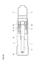
- Fig. 1 is an external perspective view of a water gun 1 according to an embodiment of the invention
- Fig. 2 is an exploded perspective view of the water gun 1 according to the embodiment.
- a side from which a jet of water is forcibly discharged is referred to as a front direction
- a side where an operating portion resides is referred to as a rear direction
- left and right sides of the water gun 1 with respect to the front direction in which a jet of water is discharged are referred to as a left direction and a right direction, respectively.
- an upper side and a lower side of the water gun 1 shown in the external perspective view shown in Fig. 1 are referred to as an upward direction and a downward direction, respectively.
- the water gun 1 has a casing 10 that imitates a gun barrel and a main body of a gun, a rear grip portion 12 that is provided so as to extend downwards from a rear end of the casing 10 and which imitates a grip portion of the gun and a front grip portion 11 that is provided so as to extend downwards from a middle portion of the casing 10 and which imitates a magazine of the gun.
- a rear half portion of the casing 10 is made into an operating portion 9 which is made to slide forwards and backwards relative to a front half portion of the casing 10.
- the front half portion of the casing 10 is made into a front casing 8.
- the front casing 8 has in an interior thereof two cylinders which are a cylinder having a piston room defined in a front portion thereof and a cylinder having a piston room defined in a rear portion thereof.
- the front casing 8 also has in the interior thereof pumping tubing 50 that is formed of a flexible tube and which extends downwards from the front grip portion 11 that imitates a magazine of a gun.
- the operating portion 9, which is the rear half portion of the casing 10 can be pulled out and pushed in by holding the front grip portion 11 by the left hand, for example, and holding the rear grip portion 12 by the right hand so as to move the operating portion 9 backwards and forwards.
- water is allowed to jet from a distal end of the casing 10 that imitates the barrel of a gun.
- the water gun 1 includes the pumping tubing 50 which has the flexible tube that is formed of a resin or a rubber and which makes up a pumping path 51 which is suspended downwards from the front grip portion 11 for pumping up water and a spherical body that is provided at a distal end of the flexible tube and which is partially opened for pumping up water therefrom.
- This pumping tubing 50 is used to pump up water from a washbasin, a bucket or a bathtub where water is stored by keeping the spherical body at the lower end of the suspended tubing 50 floating in the water so that the water so pumped up is allowed to jet from a front end of the front casing 8.
- the water gun 1 includes a muzzle portion 4 from which water is caused to jet.
- the muzzle portion 4 is formed into a substantially conical shape which tapers as it extends forwards by forming an inclined surface at the front end of the front casing 8.
- the water gun 1 is formed so that a pump mechanism 40 is encompassed in an interior of the cover members which are coupled together.
- the water gun 1 is made up of a right front cover member 2, a left front cover member 3, a right rear cover member 5 and a left rear cover member 6 that are made of a hard resin and which are coupled together so as to form all side surfaces of the water gun 1.
- the right front cover member 2 and the left front cover member 3 are fitted on or in each other and are joined together at screw fastening portions 70, 71 of the right front cover member 2 and screw fastening portions 80, 81 of the left front cover member 3.
- right rear cover member 5 and the left rear cover member 6 are also joined together at screw fastening portions or joining portions, not shown, which are provided therein with screws.
- the right rear cover member 5 is made to act as the operating portion 9 and is allowed to slide forwards and backwards relative to the right front cover member 2.
- two cylindrical engagement projections 61 are provided so as to be aligned in a front-to-rear direction within an interior of the right front cover member 2, while an engagement opening 62 is formed in the right rear cover member 5 so as to extend in the front-to-rear direction into an elliptic shape, and this engagement opening 62 has a width which is substantially equal to the diameter of the engagement projection 61. Then, the engagement projections 61 are inserted through the engagement opening 62 so that distal ends of the engagement projections 61 project into the right rear cover member 5, whereby the operating portion 9 is allowed to slide only forwards and backwards.
- the pump mechanism 40 In holding the pump mechanism 40 within the water gun 1, the pump mechanism 40 is supported by openings and ribs which are formed in the cover members while being brought into engagement therewith.
- two arc-shaped fixing ribs 66 are formed in the interior of the right front cover member 2 to fix in place a first cylinder 20 of the pump mechanism 40 that is held therein.
- ribs are also formed in an interior of the left front cover member 3 to fix in place a second cylinder 30 of the pump mechanism 40 within the casing.
- an accommodating rib 65 is formed in the interior of the right front cover member 2 to accommodate the pumping tubing 50 in a predetermined position in the water gun 1 so as to guide the pumping tubing 50 to a position lying below the front grip portion 11.
- an engagement rib 27 is formed in an interior of each of the right rear cover member 5 and the left rear cover member 6 for engagement with a T-shaped engagement portion 26 which is formed at the rear of an interlocking member 25 of the pump mechanism 40.
- the engagement rib 27 is formed by cutting out individually distal ends of two flat plate-like ribs into a U-like shape.
- the pump mechanism 40 includes the first cylinder 20 which is situated in an upper position, a first piston 21 which operates within the first cylinder 20, the second cylinder 30 which is situated in a lower position, a second piston 31 which operates within the second cylinder 30, the interlocking member 25 that is situated in an intermediate position between the first cylinder 20 and the second cylinder 30 and which is connected to the individual pistons, the pumping tubing 50 which makes up a pumping path 51 through which water is pumped up into the first cylinder 20 and the second cylinder 30, and a water supply path 52 through which water is pumped up from the second cylinder 30 to the muzzle portion 4 which is connected to the front of the first cylinder 20.
- the first cylinder 20 is made of a hard resin material and is formed into a cylindrical shape.
- the first cylinder 20 is positioned above and at the front of the interlocking member 25 and is connected to the muzzle portion 4 which is formed into the substantially conical shape at the front thereof. Additionally, the pumping tubing 50 is connected to a left front portion of the first cylinder 20.
- the second cylinder 30 is made of a hard resin material and is formed into a cylindrical shape.
- the second cylinder 30 is positioned below and at the rear of the interlocking member 25.
- the pumping tubing 50 is connected to a left rear portion of the second cylinder 30.
- the water supply path 52 connects a right rear portion of the second cylinder 30 with the muzzle portion 4 so that water is pushed out from the second cylinder 30 into the muzzle portion 4 by way of the water supply path 52.
- the first piston 21 is connected to the interlocking member 25 above the interlocking member 25, and the second piston 31 is connected to the interlocking member 25 below the interlocking member 25.
- the first piston 21 and the second piston 31 are connected to the interlocking member 25 in such a state that they are oriented in opposite directions and can be pressed in an alternate fashion.
- the interlocking member 25 is made of a hard resin material and has a rod-shaped portion that is formed as an integral unit in which three elongated plate materials which are disposed so as to extend in the front-to-rear direction while being erected individually in a vertical direction from one longer side thereof and a single vertical plate material are connected together.
- this rod-shaped portion two rectangular plate materials are coupled integrally to a rear end portion of the rod-shaped portion so that the two plate materials are oriented at right angles to the rod-shaped portion with respect to the front-to-rear direction, whereby the T-shaped engagement portion 26 is formed integral with the rod-shaped portion.
- a pivot is provided on the interlocking member 25 so as to be erected therefrom.
- This pivot is provided for a piston rod which is situated at the rear of the first piston 21 which is disposed parallel to an upper surface of a front portion of the interlocking member 25. Then, this pivot is press fitted in a hole portion in the piston rod which is situated at the rear of the first piston 21, whereby the interlocking member 25 and the first piston 21 are integrated with each other.
- FIG. 5 is a horizontal sectional view taken along the plane A-A shown in Fig. 3 which shows a lower main part of the pump mechanism 40, including the cover members.
- Fig. 6 is a horizontal sectional view taken along the plane B-B shown in Fig. 3 which shows an upper main part of the pump mechanism 40, including the cover members.
- the pumping path 51 which communicates with the pumping tubing 50 is connected to a left rear portion of the second cylinder 30 which is disposed below the first cylinder 20and the water supply path 52 is connected to a right rear portion thereof.
- the pumping path 51 and the water supply path 52 are connected to the positions on the second cylinder 30 which are situated symmetrically with respect to an axis of the cylinder 30.
- a pumping check valve 42 and a discharging check valve 43 are incorporated in interiors of connecting portions between the respective paths and the second cylinder 30.
- a water supply opening portion 33 is provided near the pumping check valve 42 and the discharging check valve 43 in an interior of the second cylinder 30.
- This water supply opening portion 33 is opened at a distal end thereof and is formed into a hollow conical shape, whereby a flow of water is restricted.
- the pumping check valve 42 is made up of a circular rubber or resin material and has a diameter which is larger than a bore diameter of a hole portion which is opened in a wall surface of the second cylinder 30 so that the pumping check valve 42 is disposed thereat.
- the pumping check vale 42 is made to open its valve element toward an inside of the cylinder 30 which is a side where water pumped up by way of the pumping path 51 by pulling out the second piston 31 for suction of water is allowed to enter the interior of the cylinder 30.
- the discharging check valve 43 is also made up of a circular rubber or resin material and has a diameter which is larger than a bore diameter of a hole portion which is opened in a wall surface of the second cylinder 30 so that the discharging check valve 43 is disposed thereat.
- the discharging check vale 43 is made to open its valve element toward an outside of the cylinder 30 which is a side where water is supplied into the jet water flowing chamber 22 within the muzzle portion 4 by way of the water supply path 52 when the second piston 31 is pushed in for pressing water stored in the second cylinder 30.
- the muzzle portion 4 is integrated with a front end of the first cylinder 20.
- a muzzle is formed in a front end of the muzzle portion 4 and the jet water flowing chamber 22 is formed in an interior of the muzzle portion 4.
- the water supply path 52 is connected to a right-hand side of the jet water flowing chamber 22.
- a discharging check valve 45 is provided at a portion through which water is supplied from the first cylinder 20 into the jet water flowing chamber 22.
- the pumping path 51 which communicates with the pumping tubing 50 is connected to a left front portion of the first cylinder 20.
- a pumping check valve 41 is incorporated in an interior of the first cylinder 20 in a position where the pumping path 51 is connected to the first cylinder 20.
- a water supply opening portion 23 is provided near the pumping check valve 41 in the interior of the first cylinder 20.
- This a water supply opening portion 23 is opened at a distal end thereof and has a hollow conical shape.
- the water supply opening portion 23 restricts a flow of water.
- the pumping check valve 41 is made up of a circular rubber or resin material and has a diameter which is larger than a bore diameter of a hole portion which is opened in a wall surface of the first cylinder 20 so that the pumping check valve 41 is disposed thereat.
- the pumping check vale 41 is made to open its valve element toward an inside of the cylinder 20 which is a side where water pumped up by way of the pumping path 51 by pulling out the first piston 21 for suction of water is allowed to enter the interior of the cylinder 20.
- the pumping check valve 41 is held in a closed state.
- the discharging check valve 45 is also made up of a circular rubber or resin material and has a diameter which is larger than a bore diameter of a hole portion where the discharging check valve 45 is disposed and through which water is supplied from the first cylinder 20 into the jet water flowing chamber 22.
- the discharging check vale 45 is made to open its valve element when the first piston 21 is pushed in to press water within the first cylinder 20.
- the second piston 30 is moved to the front so as to expand a space within the second cylinder 30 of the pump mechanism 40 for suction of water thereinto as shown in Fig. 5 , whereby water is pumped up from the water storage tank into the expanded space in the second cylinder 30 by way of the pumping path 51 that is connected to the rear of the second cylinder 30. Then, the resin or rubber pumping check valve 42 is opened, whereby water is stored within the second cylinder 30.
- the first piston 21 is moved to the front in association with the forward movement of the second piston 31, whereby water is stored within the second cylinder 30, and at the same time, the first piston 21 compresses a space within the first cylinder 20 which is positioned upper in the pump mechanism 40 so as to narrow the space while pressing the corresponding cylinder 20.
- This opens the resin or rubber discharging check valve 45 shown in Fig. 6 so that water that has already been stored in the first cylinder 20 which is referred to as a first storage tank is discharged into the jet water flowing chamber 22, allowing the water so flowing into the jet water flowing chamber 22 to jet from the muzzle portion 4.
- the first piston 21 is moved to the rear so as to expand the space within the first cylinder 20 of the pump mechanism 40 for suction of water thereinto, whereby water is pumped up from the water storage tank by way of the pumping path 51. Then, the resin or rubber pumping check valve 41 shown in Fig. 6 is opened so as to allow water to be taken into the first cylinder 20 which is referred to as the first storage tank for storage therein.
- the second cylinder 30 and the first cylinder 20 are aligned so as to be situated substantially in such a position as a front end of the second piston 31 being aligned with the front end of the first cylinder 20 when the second piston 31 in the second cylinder 30 in which the piston room is defined in the rear portion is advanced as shown in Figs. 3 and 4 .
- the second cylinder 30 and the first cylinder 20 are used which have the same size and the substantially identical construction. Therefore, although not shown, the second cylinder 30 and the first cylinder 20 are situated substantially in such a position as a rear end of the first piston 21 being aligned with a rear end of the second cylinder 30 when the first piston 21 of the first cylinder 20 is withdrawn.
- an operating range of the rear end of the first piston 21 is made to fall within a range defined by a longitudinal length of the second cylinder 30, while an operating range of the rear end of the second piston 31 is made to fall within a range defined by a longitudinal length of the first cylinder 20.
- first cylinder 20 and the second cylinder 30 which have the same size are used, bore diameters of the first cylinder 20 and the second cylinder 30 are the same.
- a quantity of water that is allowed to jet from the muzzle portion 4 when the operating portion 9 is moved to the front becomes the same as a quantity of water that is allowed to jet from the muzzle portion 4 when the operating portion 9 is moved to the rear, and therefore, there exists no difference in quantity of water to jet from the muzzle portion 4 between when the operating portion 9 is moved to the front and when the operating portion 9 is moved to the rear, whereby the user can play with the water gun 1 without uncomfortable feeling when the player operates the operating portion 9.
- the pump mechanism 40 is described as being configured so that the first cylinder 20 which is positioned upper and the second cylinder 30 which is positioned lower are pressed in the alternate fashion, the invention is not limited thereto.
- the water gun 1 of this embodiment is formed into the machine gun, the invention is not limited thereto.
- the invention is not limited thereto.
- the water gun 1 which allows water to jet therefrom with the operating portion 9 being pushed in and pulled out.
- the water gun 1 is formed into a machine gun and has the magazine-shaped grip portion and the grip-shaped grip portion, a child who plays with this water gun can feel the charm of a shooting game when the child discharge the water gun.
- the pumping tubing 50 forming the pumping path 51 is formed of the flexible tube, the pumping tubing 50 has flexibility and hence can be handled freely.
- first piston 21 and the second piston 31 are made to press alternately the first cylinder 20 and the second cylinder 30 of the pump mechanism 40 within the first cylinder 20 and the second cylinder 30 in the pump mechanism 40, whereby it is possible for water to jet from the water gun 1.
Landscapes
- Engineering & Computer Science (AREA)
- General Engineering & Computer Science (AREA)
- Toys (AREA)
- Reciprocating Pumps (AREA)
Applications Claiming Priority (1)
| Application Number | Priority Date | Filing Date | Title |
|---|---|---|---|
| JP2011276834A JP2013127335A (ja) | 2011-12-19 | 2011-12-19 | 水鉄砲玩具 |
Publications (2)
| Publication Number | Publication Date |
|---|---|
| EP2607835A2 true EP2607835A2 (de) | 2013-06-26 |
| EP2607835A3 EP2607835A3 (de) | 2014-10-08 |
Family
ID=47603027
Family Applications (1)
| Application Number | Title | Priority Date | Filing Date |
|---|---|---|---|
| EP12198043.7A Withdrawn EP2607835A3 (de) | 2011-12-19 | 2012-12-19 | Wasserpistole |
Country Status (4)
| Country | Link |
|---|---|
| US (1) | US8701935B2 (de) |
| EP (1) | EP2607835A3 (de) |
| JP (1) | JP2013127335A (de) |
| CN (1) | CN103162575B (de) |
Families Citing this family (10)
| Publication number | Priority date | Publication date | Assignee | Title |
|---|---|---|---|---|
| GB2521668A (en) * | 2013-12-30 | 2015-07-01 | F Secure Corp | Locating of locating-incapable devices in a location tracking system |
| CN203928877U (zh) * | 2014-07-08 | 2014-11-05 | 朱红英 | 一种自动回位式弯曲水枪 |
| CN203928879U (zh) * | 2014-07-08 | 2014-11-05 | 朱红英 | 一种弯曲水枪 |
| CN203928878U (zh) * | 2014-07-08 | 2014-11-05 | 朱红英 | 一种限位式弯曲水枪 |
| CN105571393A (zh) * | 2015-12-24 | 2016-05-11 | 李峰 | 一种玩具水枪 |
| CN106767146B (zh) * | 2016-12-22 | 2018-04-17 | 福建铭塔玩具股份有限公司 | 一种儿童玩具水枪 |
| CN107976109B (zh) * | 2016-12-22 | 2019-07-19 | 绍兴柯桥诚鑫精密铸造有限公司 | 一种玩具水枪结构 |
| CN107764129A (zh) * | 2017-12-07 | 2018-03-06 | 广州灵动创想文化科技有限公司 | 一种多种出水方式的玩具水枪喷头及玩具水枪 |
| US10935341B2 (en) * | 2018-08-10 | 2021-03-02 | Spin Master, Inc. | Liquid jet ejection device |
| CN114459282B (zh) * | 2022-02-14 | 2024-02-20 | 东莞市山普斯科技有限公司 | 自动水枪 |
Citations (1)
| Publication number | Priority date | Publication date | Assignee | Title |
|---|---|---|---|---|
| JP2005312473A (ja) | 2004-04-26 | 2005-11-10 | Eishindo:Kk | 水鉄砲玩具 |
Family Cites Families (14)
| Publication number | Priority date | Publication date | Assignee | Title |
|---|---|---|---|---|
| JPS57179599A (en) * | 1981-04-25 | 1982-11-05 | Sekiden Kaihatsu Shoji Kk | Toy gun |
| JPS5877298U (ja) * | 1981-11-19 | 1983-05-25 | 清水 哲吾 | 玩具ウオ−タ−ガン |
| GB2145340A (en) * | 1983-07-06 | 1985-03-27 | Mak S Ind Company Limited | Water pistol |
| JPS62166490U (de) * | 1986-04-10 | 1987-10-22 | ||
| CN2109232U (zh) * | 1992-01-18 | 1992-07-08 | 郭天翔 | 能连续发射的自动玩具水枪 |
| US5439139A (en) * | 1994-01-31 | 1995-08-08 | Lanard Toys Limited | Toy water gun |
| USD372506S (en) * | 1994-08-02 | 1996-08-06 | Royal Co., Ltd. | Water machine gun |
| US5622159A (en) * | 1995-05-05 | 1997-04-22 | Lcd International, L.L.C. | Toy weapon firing a shapeless semi-solid charge |
| US5730325A (en) * | 1996-05-20 | 1998-03-24 | Cheung; David Tat Wai | Toy water gun |
| US5829635A (en) * | 1997-02-24 | 1998-11-03 | Lanard Toys, Ltd. | Toy water gun having a continuous water output |
| US6067975A (en) * | 1998-05-05 | 2000-05-30 | Hasbro, Inc. | Pulsating toy gun having reciprocating barrels |
| CN2659489Y (zh) * | 2003-12-05 | 2004-12-01 | 黑龙江省森林保护研究所 | 高压贮能灭火水枪 |
| CN2672606Y (zh) * | 2004-02-03 | 2005-01-19 | 童乐思有限公司 | 单嘴电动玩具水枪 |
| CN201710974U (zh) * | 2010-03-04 | 2011-01-19 | 松瑞有限公司 | 一种电动玩具水枪 |
-
2011
- 2011-12-19 JP JP2011276834A patent/JP2013127335A/ja active Pending
-
2012
- 2012-12-18 US US13/718,561 patent/US8701935B2/en not_active Expired - Fee Related
- 2012-12-19 CN CN201210555320.4A patent/CN103162575B/zh not_active Expired - Fee Related
- 2012-12-19 EP EP12198043.7A patent/EP2607835A3/de not_active Withdrawn
Patent Citations (1)
| Publication number | Priority date | Publication date | Assignee | Title |
|---|---|---|---|---|
| JP2005312473A (ja) | 2004-04-26 | 2005-11-10 | Eishindo:Kk | 水鉄砲玩具 |
Also Published As
| Publication number | Publication date |
|---|---|
| US20130153599A1 (en) | 2013-06-20 |
| CN103162575B (zh) | 2016-01-27 |
| CN103162575A (zh) | 2013-06-19 |
| US8701935B2 (en) | 2014-04-22 |
| JP2013127335A (ja) | 2013-06-27 |
| EP2607835A3 (de) | 2014-10-08 |
Similar Documents
| Publication | Publication Date | Title |
|---|---|---|
| US8701935B2 (en) | Water gun | |
| US7963281B2 (en) | Electric toy gun and motion control mechanism thereof | |
| US8336531B2 (en) | Reconfigurable toy gun with a slidable barrel | |
| US20100022160A1 (en) | Toy gun mechanism with a sliding bolt assembly | |
| US9134089B2 (en) | Airsoft guns structure with improved reality and safety gasification system for the compressed gas cartridge | |
| US10852098B1 (en) | Toy gun with a toggleable grip | |
| US7686003B2 (en) | Manually powered projectile launcher | |
| CN105444615A (zh) | 玩具枪 | |
| US20110041825A1 (en) | Gun-lock assembly | |
| US20090007896A1 (en) | Pneumatically and Manually Actuating Toy Gun Structure | |
| US20120178338A1 (en) | Toy Gun | |
| US12025403B2 (en) | Toy fluid launcher and method of using same | |
| US8286622B2 (en) | Valve with blow back reservoir | |
| EP2899490B1 (de) | Elektrische Spielzeugpistole | |
| US10731941B1 (en) | Kickback structure for a toy gun | |
| GB2145340A (en) | Water pistol | |
| EP1513615A4 (de) | Membranwasserpistole | |
| US7597096B2 (en) | Gas gun having an air driving device | |
| EP2275768A2 (de) | Spielzeugwaffe mit Rückstossmechanismus | |
| TWI720900B (zh) | 應用在玩具槍的機匣組件 | |
| US20030051717A1 (en) | Automatic compressed air distributor | |
| US20060207999A1 (en) | Toy water gun | |
| US3040932A (en) | Toy liquid ejecting pistol | |
| HK1186516A (en) | Water gun | |
| US227789A (en) | Albert g |
Legal Events
| Date | Code | Title | Description |
|---|---|---|---|
| AK | Designated contracting states |
Kind code of ref document: A2 Designated state(s): AL AT BE BG CH CY CZ DE DK EE ES FI FR GB GR HR HU IE IS IT LI LT LU LV MC MK MT NL NO PL PT RO RS SE SI SK SM TR |
|
| AX | Request for extension of the european patent |
Extension state: BA ME |
|
| PUAI | Public reference made under article 153(3) epc to a published international application that has entered the european phase |
Free format text: ORIGINAL CODE: 0009012 |
|
| PUAL | Search report despatched |
Free format text: ORIGINAL CODE: 0009013 |
|
| AK | Designated contracting states |
Kind code of ref document: A3 Designated state(s): AL AT BE BG CH CY CZ DE DK EE ES FI FR GB GR HR HU IE IS IT LI LT LU LV MC MK MT NL NO PL PT RO RS SE SI SK SM TR |
|
| AX | Request for extension of the european patent |
Extension state: BA ME |
|
| RIC1 | Information provided on ipc code assigned before grant |
Ipc: F41B 9/00 20060101AFI20140903BHEP |
|
| STAA | Information on the status of an ep patent application or granted ep patent |
Free format text: STATUS: THE APPLICATION IS DEEMED TO BE WITHDRAWN |
|
| 18D | Application deemed to be withdrawn |
Effective date: 20150409 |