EP2607875B1 - Capteur de pression d'un fluide en écoulement et distributeur de fluide doté d'un tel capteur de pression - Google Patents
Capteur de pression d'un fluide en écoulement et distributeur de fluide doté d'un tel capteur de pression Download PDFInfo
- Publication number
- EP2607875B1 EP2607875B1 EP11194612.5A EP11194612A EP2607875B1 EP 2607875 B1 EP2607875 B1 EP 2607875B1 EP 11194612 A EP11194612 A EP 11194612A EP 2607875 B1 EP2607875 B1 EP 2607875B1
- Authority
- EP
- European Patent Office
- Prior art keywords
- pressure sensor
- pressure
- channel
- fluid
- conveying
- Prior art date
- Legal status (The legal status is an assumption and is not a legal conclusion. Google has not performed a legal analysis and makes no representation as to the accuracy of the status listed.)
- Active
Links
Images
Classifications
-
- G—PHYSICS
- G01—MEASURING; TESTING
- G01L—MEASURING FORCE, STRESS, TORQUE, WORK, MECHANICAL POWER, MECHANICAL EFFICIENCY, OR FLUID PRESSURE
- G01L19/00—Details of, or accessories for, apparatus for measuring steady or quasi-steady pressure of a fluent medium insofar as such details or accessories are not special to particular types of pressure gauges
- G01L19/0007—Fluidic connecting means
- G01L19/0023—Fluidic connecting means for flowthrough systems having a flexible pressure transmitting element
-
- G—PHYSICS
- G01—MEASURING; TESTING
- G01L—MEASURING FORCE, STRESS, TORQUE, WORK, MECHANICAL POWER, MECHANICAL EFFICIENCY, OR FLUID PRESSURE
- G01L19/00—Details of, or accessories for, apparatus for measuring steady or quasi-steady pressure of a fluent medium insofar as such details or accessories are not special to particular types of pressure gauges
- G01L19/06—Means for preventing overload or deleterious influence of the measured medium on the measuring device or vice versa
- G01L19/0627—Protection against aggressive medium in general
- G01L19/0645—Protection against aggressive medium in general using isolation membranes, specially adapted for protection
-
- G—PHYSICS
- G01—MEASURING; TESTING
- G01L—MEASURING FORCE, STRESS, TORQUE, WORK, MECHANICAL POWER, MECHANICAL EFFICIENCY, OR FLUID PRESSURE
- G01L19/00—Details of, or accessories for, apparatus for measuring steady or quasi-steady pressure of a fluent medium insofar as such details or accessories are not special to particular types of pressure gauges
- G01L19/14—Housings
- G01L19/147—Details about the mounting of the sensor to support or covering means
Definitions
- the present invention relates to a fluid flowed through by a pressure sensor and a conveyor with such a flow-through pressure sensor.
- the technical field of the invention relates to the pressure measurement of fluids, such as viscous media or liquids, such as adhesives or sealants, paints, varnishes, solvents, suspensions, viscous raw materials, emulsions, pastes, food pastes, oils or fats.
- fluids such as viscous media or liquids, such as adhesives or sealants, paints, varnishes, solvents, suspensions, viscous raw materials, emulsions, pastes, food pastes, oils or fats.
- the processor uses conveying and metering devices for the removal or further processing of the viscous medium. After or even during the delivery of the viscous medium, the current pressure of the viscous medium is of interest to the processor or to the processing.
- Dosing devices which are suitable for such a dosage can be based on a gear pump or an eccentric screw pump or designed, for example, as a spindle conveyor.
- a metering device can also be designed as a valve, for example as a spindle valve, as a pressure-time valve or as a volume valve.
- a dead space can arise.
- the resulting dead space can degrade the repeatability and / or the controllability of the dosage.
- fluid can harden in the resulting dead space.
- the pressure sensor can not be cleaned optimally. In such a case, it is no longer possible to ensure that the measurement results of the pressure sensor are correct.
- the object is achieved by a pressure sensor for measuring a pressure of a fluid flowing through the pressure sensor with the features of claim 1 and by a conveying device for conveying a fluid having the features of claim 14.
- the flow-through pressure sensor has a housing, a channel disposed in the housing for conveying the fluid from an input section to an output section, a pressure transmitter embedded in the housing for outputting an electrical signal proportional to the pressure of the fluid flowing through the channel, and an intermediate channel and the pressure transmitter arranged pressure transmitter of at least one elastomer for transmitting the pressure of the fluid flowing through the channel to the pressure transducer.
- the pressure transducer By embedding or integration of the pressure transducer in the housing of the pressure sensor any dead space is prevented or avoided. Furthermore, the pressure sensor is advantageously flowed through by the fluid. Consequently, the present pressure sensor may also be referred to as a flow-through pressure sensor.
- the pressure transducer may also be referred to as a pressure transducer because it converts the pressure of the fluid in the channel of the pressure sensor into an electrical signal. The electrical signal is in the millivolt range, for example.
- the elastomer in particular forms a jacket around the channel as well as the at least one part of the pressure transmitter.
- the elastomer is thus part of the pressure transmitter and therefore part of the pressure sensor, which is consequently a pressure sensor through which the fluid flows.
- the elastomer forms not only the jacket, but also an increase, for example, in the form of a protruding in the direction of the pressure transmitter cylinder.
- the jacket of the channel forming elastomer may also be referred to as an inliner.
- the pressure transducer is integrated on a chip.
- the integration of the pressure transducer on a chip or microchip has the advantage of
- the pressure transducer can be easily integrated into the pressure sensor.
- the chip is connected to a carrier board, which is adapted to hold the chip and forward the output from the pressure transducer electrical signal to a coupled to the carrier evaluation electronics.
- the carrier board can also be formed from two individual boards, which are connected via a flex strip and which are arranged one above the other in the horizontal direction.
- the transmitter is integrated in the housing.
- the evaluation is designed for example as a microcontroller. By integrating the transmitter in the housing of the pressure sensor, this can output a preprocessed electrical signal which is directly proportional to the measured pressure of the fluid in the channel of the pressure sensor.
- the pressure transducer is embedded in the housing between the pressure transmitter and the carrier plate by means of potting a viscoelastic potting material.
- Viscoelastic means that the potting material is partially elastic and partially viscous behavior. The viscoelasticity of the potting material is based on a delayed equilibration of the macromolecules of the potting material to each other during or after mechanical stress.
- the potting material is a silicone or an epoxy resin. Silicone is a particularly suitable potting material for potting the pressure transducer in the housing between the elastomer of the liner and the carrier board.
- the pressure transmitter is formed from the elastomer and partly from the potting material.
- the elastomer of the pressure transmitter is a perfluoroelastomer.
- the pressure transducer and the pressure sensor are firmly connected to each other.
- the entrance section of the channel has a female cone female luer taper and the male channel male luer taper has the male section of the canal.
- the entrance section of the channel has a male male tapered luer cone and the outlet section of the channel has a female taper female luer taper.
- a conveyor such as a metering device or a delivery hose.
- the pressure transducer is designed as a piezoelectric pressure transducer.
- a conveying device for conveying a fluid which comprises a pressure sensor as described above and a first conveying means for conveying the fluid, which is coupled to the input portion of the pressure sensor, and a second conveying element for conveying the fluid which communicates with the output portion of the pressure sensor is coupled.
- first conveying element and the second conveying element are each designed as a conveying hose.
- the first conveying means may also be designed as a metering device, such as an eccentric screw pump, whereas the second conveying means is designed, for example, as a metering needle.
- the fluid has a viscosity of 0.1 to 10 7 mPas, preferably from 10 1 to 10 5 mPas, particularly preferably from 10 3 to 10 4 mPas.
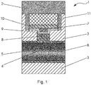
- FIG. 1 is a schematic sectional view of an embodiment of a fluid flowing through a pressure sensor 1 is shown.
- the pressure sensor 1 is suitable for measuring the pressure of the fluid flowing through the pressure sensor 1.
- the pressure sensor 1 has a housing 2, 3 consisting of an upper housing part 2 and a lower housing part 3.
- a channel 4 or a pipe for conveying the fluid from an input section 5 of the pressure sensor 1 to an output section 6 of the pressure sensor 1 is arranged.
- the lateral surface of the channel 4 has in particular an elastomer, which may also be referred to as inliner.
- a pressure transmitter 7 is embedded in the housing 2, 3.
- the pressure transducer 7 outputs an electrical signal proportional to the pressure of the fluid flowing through the channel 4, for example in the millivolt range.
- the pressure transducer 7 is integrated on a chip or microchip and can also be referred to as a pressure transducer, since it converts the prevailing pressure of the fluid in the channel 4 into a proportional electrical signal.
- the designed as a microchip 7 pressure transducer is connected to a carrier board 10.
- the carrier board 10 is adapted to support the microchip 7 and to forward the electrical signal output by the microchip 7 to an evaluation electronics 11 coupled to the carrier board 10.
- the transmitter 11 is integrated in the housing 2, 3 and formed for example as a microcontroller.
- the microcontroller 11 performs functions in particular in the field of signal preprocessing of the output from the pressure transducer 7 electrical signal.
- the microcontroller 11 can be coupled via a cable 14 to a processor or an evaluation device (see Fig. 2 and 3 ).
- a pressure transmitter 8, 9 is provided between the channel 4 and the pressure transducer 7, which is arranged to transmit the pressure of the channel 4 flowing through the fluid to the pressure transducer 7.
- the diaphragm seal 8, 9 of the Fig. 1 consists of a raised portion of the elastomer 8 and a portion of a potting material 9.
- the potting material 9 is used to embed the pressure transducer 7 by means of encapsulation in the housing 2, 3 between the elastomer 8 and the support plate 10.
- the raised edge may also be referred to as the thickening of the elastomer 8.
- the elastomer 8 is, for example, a perfluoroelastomer.
- the potting material 9 is made of, for example, silicone or an epoxy resin. In particular, the pressure transmitter 7 and the pressure transmitter 8, 9 are firmly connected.
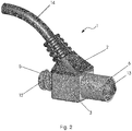
- Fig. 2 shows a perspective view of the embodiment of the pressure sensor 1 after Fig. 1 ,
- the upper housing part 2 and the lower housing part 3 of the pressure sensor 1 are visible in the outside view.
- the upper housing part 2 is connected to a cable 14 which can couple the evaluation electronics 11 of the pressure sensor 1 with a further evaluation device, for example a processor or a computer.
- the lower housing part 3 has at the input section 5 of the channel 4 a Luer cone with female inner cone 12 for coupling the pressure sensor 1 with a conveying means, for example a delivery hose for conveying the fluid. Furthermore, the lower housing part 3 has in its output region 6 of the channel 4 a Luer cone with male outer cone 13 for coupling the pressure sensor 1 with a further conveying means for conveying the fluid.
- the counterpart of the Luer cone with female inner cone 12 is a Luer cone with male outer cone of the conveyor. Accordingly, the counterpart of the Luer cone with male outer cone 13 is a Luer cone with female inner cone of the conveyor.
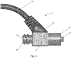
- Fig. 3 nor a side view of the embodiment of the pressure sensor 1 after Fig. 2
Landscapes
- Physics & Mathematics (AREA)
- General Physics & Mathematics (AREA)
- Chemical & Material Sciences (AREA)
- Analytical Chemistry (AREA)
- Measuring Fluid Pressure (AREA)
Claims (15)
- Capteur de pression (1) pour mesurer la pression d'un fluide traversant le capteur de pression (1), comprenant :un boîtier (2, 3),un canal (4) disposé dans le boîtier (2, 3) pour transporter le fluide d'une section d'entrée (5) à une section de sortie (6),un capteur de pression (7) intégré au boîtier (2, 3) pour émettre un signal électrique proportionnel à la pression du fluide traversant le canal (4),un médiateur de pression (8, 9) arrangé entre le capteur de pression (7) et le canal (4) pour transmettre la pression du fluide passant le canal (4) au capteur de pression (7),dans lequel au moins une partie du médiateur de pression (8, 9) est constituée d'un élastomère (8),caractérisé en ce quel'élastomère (8) forme une enveloppe autour du canal (4) et qu'un épaississement de l'élastomère (8) forme au moins une partie du médiateur de pression (8, 9).
- Capteur de pression selon la revendication 1,
caractérisé en ce que
le capteur de pression (7) est intégré à une puce. - Appareil selon la revendication 2,
caractérisé en ce que
la puce (7) est connectée à une plaque de support (10) destinée à tenir la puce (7) et à transmettre le signal électrique de la puce (7) à une unité d'évaluation électronique (11) connectée à la plaque de support (10) . - Capteur de pression selon la revendication 3,
caractérisé en ce que
l'unité d'évaluation électronique (11) est intégrée au boîtier (2, 3). - Capteur de pression selon la revendication 3 ou 4,
caractérisé en ce que
l'unité d'évaluation électronique (11) est un microcontrôleur. - Capteur de pression selon l'une des revendications 3 à 5,
caractérisé en ce que
le capteur de pression (7) est intégré au boîtier (2, 3) entre le médiateur de pression (7) et la plaque de support (10) par un coulage d'un matériau de coulage viscoélastique. - Capteur de pression selon la revendication 6,
caractérisé en ce que
le matériau de coulage viscoélastique (9) est en silicone. - Capteur de pression selon la revendication 6 ou 7,
caractérisé en ce que
le médiateur de pression (8, 9) est formé par l'élastomère (8) et au moins partiellement par le matériau de coulage (9). - Capteur de pression selon l'une des revendications 1 à 8,
caractérisé en ce que
l'élastomère (8) du médiateur de pression (8, 9) est un élastomère perfluoré. - Capteur de pression selon l'une des revendications 1 à 9,
caractérisé en ce que
le capteur de pression (7) et le médiateur de pression (8, 9) sont connectés ensembles fermement. - Capteur de pression selon l'une des revendications 1 à 10,
caractérisé en ce que
la section d'entrée (5) du canal (4) comprend un adaptateur Luer avec un cône intérieur femelle (12) et la section de sortie (6) du canal (4) comprend un adaptateur Luer avec un cône extérieur mâle (13). - Capteur de pression selon l'une des revendications 1 à 10,
caractérisé en ce que
la section d'entrée (5) du canal (4) comprend un adaptateur Luer avec un cône extérieur mâle (13) et la section de sortie (6) du canal (4) comprend un adaptateur Luer avec un cône intérieur femelle (12). - Capteur de pression selon l'une des revendications 1 à 10,
caractérisé en ce que
le capteur de pression (7) est un capteur de pression piézoélectrique. - Appareil de convoyage pour convoyer un fluide, comprenant:un capteur de pression (1) selon l'une des revendications 1 à 13, qui est traversé par un fluide lors de son utilisation,un premier élément de convoyage pour convoyer le fluide, qui est connecté à la section d'entrée (5) du capteur de pression (1), etun deuxième élément de convoyage pour convoyer le fluide, qui est connecté à la section de sortie (6) du capteur de pression (1).
- Appareil de convoyage selon la revendication 14,
caractérisé en ce que
le premier élément de convoyage et le deuxième élément de convoyage sont respectivement des tuyaux de convoyage.
Priority Applications (1)
| Application Number | Priority Date | Filing Date | Title |
|---|---|---|---|
| EP11194612.5A EP2607875B1 (fr) | 2011-12-20 | 2011-12-20 | Capteur de pression d'un fluide en écoulement et distributeur de fluide doté d'un tel capteur de pression |
Applications Claiming Priority (1)
| Application Number | Priority Date | Filing Date | Title |
|---|---|---|---|
| EP11194612.5A EP2607875B1 (fr) | 2011-12-20 | 2011-12-20 | Capteur de pression d'un fluide en écoulement et distributeur de fluide doté d'un tel capteur de pression |
Publications (2)
| Publication Number | Publication Date |
|---|---|
| EP2607875A1 EP2607875A1 (fr) | 2013-06-26 |
| EP2607875B1 true EP2607875B1 (fr) | 2018-02-14 |
Family
ID=45418451
Family Applications (1)
| Application Number | Title | Priority Date | Filing Date |
|---|---|---|---|
| EP11194612.5A Active EP2607875B1 (fr) | 2011-12-20 | 2011-12-20 | Capteur de pression d'un fluide en écoulement et distributeur de fluide doté d'un tel capteur de pression |
Country Status (1)
| Country | Link |
|---|---|
| EP (1) | EP2607875B1 (fr) |
Families Citing this family (6)
| Publication number | Priority date | Publication date | Assignee | Title |
|---|---|---|---|---|
| JP5594541B2 (ja) * | 2012-02-09 | 2014-09-24 | Smc株式会社 | 圧力検出器 |
| CN104729786B (zh) * | 2015-03-24 | 2017-03-01 | 长沙理工大学 | 一种孔内灌浆压力的动态测量方法 |
| CN106840502A (zh) * | 2017-04-09 | 2017-06-13 | 单志友 | 压力传感器及其制造方法 |
| CN110631761A (zh) * | 2019-10-18 | 2019-12-31 | 刘运红 | 一种径向压力表 |
| US12138858B2 (en) | 2020-05-01 | 2024-11-12 | Voltera Inc. | Systems and methods for continuous flow control of printable material in additive manufacturing |
| CN112144534A (zh) * | 2020-10-23 | 2020-12-29 | 中国水利水电第七工程局成都水电建设工程有限公司 | 一种自清洗免维护乳浆防止器 |
Family Cites Families (2)
| Publication number | Priority date | Publication date | Assignee | Title |
|---|---|---|---|---|
| US4539998A (en) * | 1983-04-29 | 1985-09-10 | American Hospital Supply Corporation | Pressure transducer assembly |
| US5993395A (en) * | 1996-04-18 | 1999-11-30 | Sunscope International Inc. | Pressure transducer apparatus with disposable dome |
-
2011
- 2011-12-20 EP EP11194612.5A patent/EP2607875B1/fr active Active
Non-Patent Citations (1)
| Title |
|---|
| None * |
Also Published As
| Publication number | Publication date |
|---|---|
| EP2607875A1 (fr) | 2013-06-26 |
Similar Documents
| Publication | Publication Date | Title |
|---|---|---|
| EP2607875B1 (fr) | Capteur de pression d'un fluide en écoulement et distributeur de fluide doté d'un tel capteur de pression | |
| DE102014106706B4 (de) | Vorrichtung zum Bestimmen von Eigenschaften eines Mediums | |
| DE102013100889B4 (de) | Druckdetektor | |
| DE102007012106B4 (de) | Drucksensor | |
| DE102009027581A1 (de) | Messvorrichtung umfassend eine Messsonde und eine Befestigungsvorrichtung | |
| DE102010056279B4 (de) | Vortex-Durchflussmessgerät mit optimierter Temperaturerfassung | |
| DE19637763A1 (de) | Drucksensoreinheit, insbesondere für die Kraftfahrzeugtechnik | |
| DE112011101128T5 (de) | Struktur mit einer Nut zur Befestigung in einer Form und Abdichten von Medien | |
| DE102011118921B4 (de) | Vortex-Durchflussmessgerät und diesbezügliche Faserdurchführung | |
| AT508805A1 (de) | Durchflussmesseinrichtung | |
| EP1764587A2 (fr) | Débitmètre à induction magnétique muni d'un disque de mise à la terre | |
| EP2022571A1 (fr) | Dispositif de dosage destiné au dosage d'un liquide | |
| DE102009028033A1 (de) | Drucksensoranordnung | |
| DE10392824T5 (de) | Preiswerter kapazitiver in sich geschlossener Druckgeber mit Plattenbeschichtung, Teilchenfilter | |
| EP3108213A1 (fr) | Ensemble capteur servant à déterminer au moins un paramètre d'un milieu fluide s'écoulant dans un conduit | |
| EP3207296B1 (fr) | Bride hybride | |
| EP1402241B1 (fr) | Systeme de transmission de pression a dispositif de reconnaissance de rupture de membrane | |
| DE10147124B4 (de) | Ölgekapselter Drucksensor mit einer Metallmembran, die über ein Druckteil am Gehäuse befestigt ist | |
| DE202005021832U1 (de) | Magnetisch induktiver Durchflussmesser mit galvanischen Messelektroden | |
| EP1255098B1 (fr) | Fluide à transfert pour la mesure de pression et son application | |
| DE202015101180U1 (de) | Manometeranordnung | |
| AT507198B1 (de) | Kraftmessring mit einem ringförmigen gehäuse | |
| EP2407696A3 (fr) | Dispositif de soupape et procédé d'établissement d'une position de commutation d'une soupape | |
| EP3178301A1 (fr) | Appareil de terrain de la technique d'automatisation | |
| DE2317321B1 (de) | Vorrichtung zur Messung rheologischer Größen fließfähiger Substanzen mit zwei verschiedenen Meßrohren |
Legal Events
| Date | Code | Title | Description |
|---|---|---|---|
| AK | Designated contracting states |
Kind code of ref document: A1 Designated state(s): AL AT BE BG CH CY CZ DE DK EE ES FI FR GB GR HR HU IE IS IT LI LT LU LV MC MK MT NL NO PL PT RO RS SE SI SK SM TR |
|
| AX | Request for extension of the european patent |
Extension state: BA ME |
|
| PUAI | Public reference made under article 153(3) epc to a published international application that has entered the european phase |
Free format text: ORIGINAL CODE: 0009012 |
|
| 17P | Request for examination filed |
Effective date: 20131223 |
|
| RBV | Designated contracting states (corrected) |
Designated state(s): AL AT BE BG CH CY CZ DE DK EE ES FI FR GB GR HR HU IE IS IT LI LT LU LV MC MK MT NL NO PL PT RO RS SE SI SK SM TR |
|
| GRAP | Despatch of communication of intention to grant a patent |
Free format text: ORIGINAL CODE: EPIDOSNIGR1 |
|
| STAA | Information on the status of an ep patent application or granted ep patent |
Free format text: STATUS: GRANT OF PATENT IS INTENDED |
|
| INTG | Intention to grant announced |
Effective date: 20170728 |
|
| GRAS | Grant fee paid |
Free format text: ORIGINAL CODE: EPIDOSNIGR3 |
|
| GRAA | (expected) grant |
Free format text: ORIGINAL CODE: 0009210 |
|
| STAA | Information on the status of an ep patent application or granted ep patent |
Free format text: STATUS: THE PATENT HAS BEEN GRANTED |
|
| AK | Designated contracting states |
Kind code of ref document: B1 Designated state(s): AL AT BE BG CH CY CZ DE DK EE ES FI FR GB GR HR HU IE IS IT LI LT LU LV MC MK MT NL NO PL PT RO RS SE SI SK SM TR |
|
| REG | Reference to a national code |
Ref country code: GB Ref legal event code: FG4D Free format text: NOT ENGLISH |
|
| REG | Reference to a national code |
Ref country code: CH Ref legal event code: EP |
|
| REG | Reference to a national code |
Ref country code: IE Ref legal event code: FG4D Free format text: LANGUAGE OF EP DOCUMENT: GERMAN |
|
| REG | Reference to a national code |
Ref country code: DE Ref legal event code: R096 Ref document number: 502011013716 Country of ref document: DE Ref country code: AT Ref legal event code: REF Ref document number: 970166 Country of ref document: AT Kind code of ref document: T Effective date: 20180315 |
|
| REG | Reference to a national code |
Ref country code: NL Ref legal event code: MP Effective date: 20180214 |
|
| PG25 | Lapsed in a contracting state [announced via postgrant information from national office to epo] |
Ref country code: CY Free format text: LAPSE BECAUSE OF FAILURE TO SUBMIT A TRANSLATION OF THE DESCRIPTION OR TO PAY THE FEE WITHIN THE PRESCRIBED TIME-LIMIT Effective date: 20180214 Ref country code: ES Free format text: LAPSE BECAUSE OF FAILURE TO SUBMIT A TRANSLATION OF THE DESCRIPTION OR TO PAY THE FEE WITHIN THE PRESCRIBED TIME-LIMIT Effective date: 20180214 Ref country code: LT Free format text: LAPSE BECAUSE OF FAILURE TO SUBMIT A TRANSLATION OF THE DESCRIPTION OR TO PAY THE FEE WITHIN THE PRESCRIBED TIME-LIMIT Effective date: 20180214 Ref country code: NL Free format text: LAPSE BECAUSE OF FAILURE TO SUBMIT A TRANSLATION OF THE DESCRIPTION OR TO PAY THE FEE WITHIN THE PRESCRIBED TIME-LIMIT Effective date: 20180214 Ref country code: HR Free format text: LAPSE BECAUSE OF FAILURE TO SUBMIT A TRANSLATION OF THE DESCRIPTION OR TO PAY THE FEE WITHIN THE PRESCRIBED TIME-LIMIT Effective date: 20180214 Ref country code: NO Free format text: LAPSE BECAUSE OF FAILURE TO SUBMIT A TRANSLATION OF THE DESCRIPTION OR TO PAY THE FEE WITHIN THE PRESCRIBED TIME-LIMIT Effective date: 20180514 Ref country code: FI Free format text: LAPSE BECAUSE OF FAILURE TO SUBMIT A TRANSLATION OF THE DESCRIPTION OR TO PAY THE FEE WITHIN THE PRESCRIBED TIME-LIMIT Effective date: 20180214 |
|
| PG25 | Lapsed in a contracting state [announced via postgrant information from national office to epo] |
Ref country code: BG Free format text: LAPSE BECAUSE OF FAILURE TO SUBMIT A TRANSLATION OF THE DESCRIPTION OR TO PAY THE FEE WITHIN THE PRESCRIBED TIME-LIMIT Effective date: 20180514 Ref country code: GR Free format text: LAPSE BECAUSE OF FAILURE TO SUBMIT A TRANSLATION OF THE DESCRIPTION OR TO PAY THE FEE WITHIN THE PRESCRIBED TIME-LIMIT Effective date: 20180515 Ref country code: LV Free format text: LAPSE BECAUSE OF FAILURE TO SUBMIT A TRANSLATION OF THE DESCRIPTION OR TO PAY THE FEE WITHIN THE PRESCRIBED TIME-LIMIT Effective date: 20180214 Ref country code: RS Free format text: LAPSE BECAUSE OF FAILURE TO SUBMIT A TRANSLATION OF THE DESCRIPTION OR TO PAY THE FEE WITHIN THE PRESCRIBED TIME-LIMIT Effective date: 20180214 Ref country code: SE Free format text: LAPSE BECAUSE OF FAILURE TO SUBMIT A TRANSLATION OF THE DESCRIPTION OR TO PAY THE FEE WITHIN THE PRESCRIBED TIME-LIMIT Effective date: 20180214 |
|
| PG25 | Lapsed in a contracting state [announced via postgrant information from national office to epo] |
Ref country code: MT Free format text: LAPSE BECAUSE OF FAILURE TO SUBMIT A TRANSLATION OF THE DESCRIPTION OR TO PAY THE FEE WITHIN THE PRESCRIBED TIME-LIMIT Effective date: 20180214 |
|
| PG25 | Lapsed in a contracting state [announced via postgrant information from national office to epo] |
Ref country code: EE Free format text: LAPSE BECAUSE OF FAILURE TO SUBMIT A TRANSLATION OF THE DESCRIPTION OR TO PAY THE FEE WITHIN THE PRESCRIBED TIME-LIMIT Effective date: 20180214 Ref country code: PL Free format text: LAPSE BECAUSE OF FAILURE TO SUBMIT A TRANSLATION OF THE DESCRIPTION OR TO PAY THE FEE WITHIN THE PRESCRIBED TIME-LIMIT Effective date: 20180214 Ref country code: AL Free format text: LAPSE BECAUSE OF FAILURE TO SUBMIT A TRANSLATION OF THE DESCRIPTION OR TO PAY THE FEE WITHIN THE PRESCRIBED TIME-LIMIT Effective date: 20180214 Ref country code: RO Free format text: LAPSE BECAUSE OF FAILURE TO SUBMIT A TRANSLATION OF THE DESCRIPTION OR TO PAY THE FEE WITHIN THE PRESCRIBED TIME-LIMIT Effective date: 20180214 |
|
| REG | Reference to a national code |
Ref country code: DE Ref legal event code: R097 Ref document number: 502011013716 Country of ref document: DE |
|
| PG25 | Lapsed in a contracting state [announced via postgrant information from national office to epo] |
Ref country code: CZ Free format text: LAPSE BECAUSE OF FAILURE TO SUBMIT A TRANSLATION OF THE DESCRIPTION OR TO PAY THE FEE WITHIN THE PRESCRIBED TIME-LIMIT Effective date: 20180214 Ref country code: DK Free format text: LAPSE BECAUSE OF FAILURE TO SUBMIT A TRANSLATION OF THE DESCRIPTION OR TO PAY THE FEE WITHIN THE PRESCRIBED TIME-LIMIT Effective date: 20180214 Ref country code: SM Free format text: LAPSE BECAUSE OF FAILURE TO SUBMIT A TRANSLATION OF THE DESCRIPTION OR TO PAY THE FEE WITHIN THE PRESCRIBED TIME-LIMIT Effective date: 20180214 Ref country code: SK Free format text: LAPSE BECAUSE OF FAILURE TO SUBMIT A TRANSLATION OF THE DESCRIPTION OR TO PAY THE FEE WITHIN THE PRESCRIBED TIME-LIMIT Effective date: 20180214 |
|
| PLBE | No opposition filed within time limit |
Free format text: ORIGINAL CODE: 0009261 |
|
| STAA | Information on the status of an ep patent application or granted ep patent |
Free format text: STATUS: NO OPPOSITION FILED WITHIN TIME LIMIT |
|
| 26N | No opposition filed |
Effective date: 20181115 |
|
| PG25 | Lapsed in a contracting state [announced via postgrant information from national office to epo] |
Ref country code: SI Free format text: LAPSE BECAUSE OF FAILURE TO SUBMIT A TRANSLATION OF THE DESCRIPTION OR TO PAY THE FEE WITHIN THE PRESCRIBED TIME-LIMIT Effective date: 20180214 |
|
| PG25 | Lapsed in a contracting state [announced via postgrant information from national office to epo] |
Ref country code: MC Free format text: LAPSE BECAUSE OF FAILURE TO SUBMIT A TRANSLATION OF THE DESCRIPTION OR TO PAY THE FEE WITHIN THE PRESCRIBED TIME-LIMIT Effective date: 20180214 Ref country code: LU Free format text: LAPSE BECAUSE OF NON-PAYMENT OF DUE FEES Effective date: 20181220 |
|
| REG | Reference to a national code |
Ref country code: IE Ref legal event code: MM4A |
|
| REG | Reference to a national code |
Ref country code: BE Ref legal event code: MM Effective date: 20181231 |
|
| PG25 | Lapsed in a contracting state [announced via postgrant information from national office to epo] |
Ref country code: IE Free format text: LAPSE BECAUSE OF NON-PAYMENT OF DUE FEES Effective date: 20181220 |
|
| PG25 | Lapsed in a contracting state [announced via postgrant information from national office to epo] |
Ref country code: BE Free format text: LAPSE BECAUSE OF NON-PAYMENT OF DUE FEES Effective date: 20181231 |
|
| REG | Reference to a national code |
Ref country code: AT Ref legal event code: MM01 Ref document number: 970166 Country of ref document: AT Kind code of ref document: T Effective date: 20181220 |
|
| PG25 | Lapsed in a contracting state [announced via postgrant information from national office to epo] |
Ref country code: TR Free format text: LAPSE BECAUSE OF FAILURE TO SUBMIT A TRANSLATION OF THE DESCRIPTION OR TO PAY THE FEE WITHIN THE PRESCRIBED TIME-LIMIT Effective date: 20180214 |
|
| PG25 | Lapsed in a contracting state [announced via postgrant information from national office to epo] |
Ref country code: AT Free format text: LAPSE BECAUSE OF NON-PAYMENT OF DUE FEES Effective date: 20181220 |
|
| PG25 | Lapsed in a contracting state [announced via postgrant information from national office to epo] |
Ref country code: PT Free format text: LAPSE BECAUSE OF FAILURE TO SUBMIT A TRANSLATION OF THE DESCRIPTION OR TO PAY THE FEE WITHIN THE PRESCRIBED TIME-LIMIT Effective date: 20180214 |
|
| PG25 | Lapsed in a contracting state [announced via postgrant information from national office to epo] |
Ref country code: HU Free format text: LAPSE BECAUSE OF FAILURE TO SUBMIT A TRANSLATION OF THE DESCRIPTION OR TO PAY THE FEE WITHIN THE PRESCRIBED TIME-LIMIT; INVALID AB INITIO Effective date: 20111220 Ref country code: MK Free format text: LAPSE BECAUSE OF NON-PAYMENT OF DUE FEES Effective date: 20180214 |
|
| PG25 | Lapsed in a contracting state [announced via postgrant information from national office to epo] |
Ref country code: IS Free format text: LAPSE BECAUSE OF FAILURE TO SUBMIT A TRANSLATION OF THE DESCRIPTION OR TO PAY THE FEE WITHIN THE PRESCRIBED TIME-LIMIT Effective date: 20180614 |
|
| REG | Reference to a national code |
Ref country code: CH Ref legal event code: U11 Free format text: ST27 STATUS EVENT CODE: U-0-0-U10-U11 (AS PROVIDED BY THE NATIONAL OFFICE) Effective date: 20260101 |
|
| PGFP | Annual fee paid to national office [announced via postgrant information from national office to epo] |
Ref country code: DE Payment date: 20251215 Year of fee payment: 15 |
|
| PGFP | Annual fee paid to national office [announced via postgrant information from national office to epo] |
Ref country code: GB Payment date: 20251218 Year of fee payment: 15 |
|
| PGFP | Annual fee paid to national office [announced via postgrant information from national office to epo] |
Ref country code: FR Payment date: 20251217 Year of fee payment: 15 |
|
| PGFP | Annual fee paid to national office [announced via postgrant information from national office to epo] |
Ref country code: IT Payment date: 20251231 Year of fee payment: 15 |
|
| PGFP | Annual fee paid to national office [announced via postgrant information from national office to epo] |
Ref country code: CH Payment date: 20260101 Year of fee payment: 15 |