EP2607942A2 - Filtre optique multifonction pour affichage d'image stéréoscopique, et afficheur d'image stéréoscopique comprenant ce filtre - Google Patents
Filtre optique multifonction pour affichage d'image stéréoscopique, et afficheur d'image stéréoscopique comprenant ce filtre Download PDFInfo
- Publication number
- EP2607942A2 EP2607942A2 EP11818432.4A EP11818432A EP2607942A2 EP 2607942 A2 EP2607942 A2 EP 2607942A2 EP 11818432 A EP11818432 A EP 11818432A EP 2607942 A2 EP2607942 A2 EP 2607942A2
- Authority
- EP
- European Patent Office
- Prior art keywords
- display device
- optical filter
- filter layer
- stereoscopic display
- layer
- Prior art date
- Legal status (The legal status is an assumption and is not a legal conclusion. Google has not performed a legal analysis and makes no representation as to the accuracy of the status listed.)
- Granted
Links
Images



Classifications
-
- G—PHYSICS
- G02—OPTICS
- G02B—OPTICAL ELEMENTS, SYSTEMS OR APPARATUS
- G02B30/00—Optical systems or apparatus for producing three-dimensional [3D] effects, e.g. stereoscopic images
- G02B30/20—Optical systems or apparatus for producing three-dimensional [3D] effects, e.g. stereoscopic images by providing first and second parallax images to an observer's left and right eyes
- G02B30/22—Optical systems or apparatus for producing three-dimensional [3D] effects, e.g. stereoscopic images by providing first and second parallax images to an observer's left and right eyes of the stereoscopic type
- G02B30/25—Optical systems or apparatus for producing three-dimensional [3D] effects, e.g. stereoscopic images by providing first and second parallax images to an observer's left and right eyes of the stereoscopic type using polarisation techniques
-
- G—PHYSICS
- G02—OPTICS
- G02B—OPTICAL ELEMENTS, SYSTEMS OR APPARATUS
- G02B5/00—Optical elements other than lenses
- G02B5/20—Filters
- G02B5/201—Filters in the form of arrays
-
- G—PHYSICS
- G02—OPTICS
- G02B—OPTICAL ELEMENTS, SYSTEMS OR APPARATUS
- G02B30/00—Optical systems or apparatus for producing three-dimensional [3D] effects, e.g. stereoscopic images
- G02B30/20—Optical systems or apparatus for producing three-dimensional [3D] effects, e.g. stereoscopic images by providing first and second parallax images to an observer's left and right eyes
- G02B30/26—Optical systems or apparatus for producing three-dimensional [3D] effects, e.g. stereoscopic images by providing first and second parallax images to an observer's left and right eyes of the autostereoscopic type
- G02B30/27—Optical systems or apparatus for producing three-dimensional [3D] effects, e.g. stereoscopic images by providing first and second parallax images to an observer's left and right eyes of the autostereoscopic type involving lenticular arrays
-
- G—PHYSICS
- G02—OPTICS
- G02B—OPTICAL ELEMENTS, SYSTEMS OR APPARATUS
- G02B30/00—Optical systems or apparatus for producing three-dimensional [3D] effects, e.g. stereoscopic images
- G02B30/20—Optical systems or apparatus for producing three-dimensional [3D] effects, e.g. stereoscopic images by providing first and second parallax images to an observer's left and right eyes
- G02B30/26—Optical systems or apparatus for producing three-dimensional [3D] effects, e.g. stereoscopic images by providing first and second parallax images to an observer's left and right eyes of the autostereoscopic type
- G02B30/30—Optical systems or apparatus for producing three-dimensional [3D] effects, e.g. stereoscopic images by providing first and second parallax images to an observer's left and right eyes of the autostereoscopic type involving parallax barriers
- G02B30/31—Optical systems or apparatus for producing three-dimensional [3D] effects, e.g. stereoscopic images by providing first and second parallax images to an observer's left and right eyes of the autostereoscopic type involving parallax barriers involving active parallax barriers
-
- G—PHYSICS
- G02—OPTICS
- G02B—OPTICAL ELEMENTS, SYSTEMS OR APPARATUS
- G02B5/00—Optical elements other than lenses
- G02B5/20—Filters
-
- G—PHYSICS
- G02—OPTICS
- G02F—OPTICAL DEVICES OR ARRANGEMENTS FOR THE CONTROL OF LIGHT BY MODIFICATION OF THE OPTICAL PROPERTIES OF THE MEDIA OF THE ELEMENTS INVOLVED THEREIN; NON-LINEAR OPTICS; FREQUENCY-CHANGING OF LIGHT; OPTICAL LOGIC ELEMENTS; OPTICAL ANALOGUE/DIGITAL CONVERTERS
- G02F1/00—Devices or arrangements for the control of the intensity, colour, phase, polarisation or direction of light arriving from an independent light source, e.g. switching, gating or modulating; Non-linear optics
- G02F1/01—Devices or arrangements for the control of the intensity, colour, phase, polarisation or direction of light arriving from an independent light source, e.g. switching, gating or modulating; Non-linear optics for the control of the intensity, phase, polarisation or colour
- G02F1/13—Devices or arrangements for the control of the intensity, colour, phase, polarisation or direction of light arriving from an independent light source, e.g. switching, gating or modulating; Non-linear optics for the control of the intensity, phase, polarisation or colour based on liquid crystals, e.g. single liquid crystal display cells
- G02F1/1313—Devices or arrangements for the control of the intensity, colour, phase, polarisation or direction of light arriving from an independent light source, e.g. switching, gating or modulating; Non-linear optics for the control of the intensity, phase, polarisation or colour based on liquid crystals, e.g. single liquid crystal display cells specially adapted for a particular application
-
- G—PHYSICS
- G02—OPTICS
- G02F—OPTICAL DEVICES OR ARRANGEMENTS FOR THE CONTROL OF LIGHT BY MODIFICATION OF THE OPTICAL PROPERTIES OF THE MEDIA OF THE ELEMENTS INVOLVED THEREIN; NON-LINEAR OPTICS; FREQUENCY-CHANGING OF LIGHT; OPTICAL LOGIC ELEMENTS; OPTICAL ANALOGUE/DIGITAL CONVERTERS
- G02F1/00—Devices or arrangements for the control of the intensity, colour, phase, polarisation or direction of light arriving from an independent light source, e.g. switching, gating or modulating; Non-linear optics
- G02F1/01—Devices or arrangements for the control of the intensity, colour, phase, polarisation or direction of light arriving from an independent light source, e.g. switching, gating or modulating; Non-linear optics for the control of the intensity, phase, polarisation or colour
- G02F1/13—Devices or arrangements for the control of the intensity, colour, phase, polarisation or direction of light arriving from an independent light source, e.g. switching, gating or modulating; Non-linear optics for the control of the intensity, phase, polarisation or colour based on liquid crystals, e.g. single liquid crystal display cells
- G02F1/133—Constructional arrangements; Operation of liquid crystal cells; Circuit arrangements
- G02F1/1333—Constructional arrangements; Manufacturing methods
- G02F1/1335—Structural association of cells with optical devices, e.g. polarisers or reflectors
-
- H—ELECTRICITY
- H04—ELECTRIC COMMUNICATION TECHNIQUE
- H04N—PICTORIAL COMMUNICATION, e.g. TELEVISION
- H04N13/00—Stereoscopic video systems; Multi-view video systems; Details thereof
- H04N13/30—Image reproducers
- H04N13/324—Colour aspects
-
- H—ELECTRICITY
- H04—ELECTRIC COMMUNICATION TECHNIQUE
- H04N—PICTORIAL COMMUNICATION, e.g. TELEVISION
- H04N13/00—Stereoscopic video systems; Multi-view video systems; Details thereof
- H04N13/30—Image reproducers
- H04N13/332—Displays for viewing with the aid of special glasses or head-mounted displays [HMD]
- H04N13/337—Displays for viewing with the aid of special glasses or head-mounted displays [HMD] using polarisation multiplexing
Definitions
- the present invention relates to an optical filter for a stereoscopic display device and a stereoscopic display device including the same, and more particularly, to a multifunctional optical filter for a stereoscopic display device for performing a color filtering function and a three-dimensional filtering function through only a single filter and a stereoscopic display device including the same.
- a stereoscopic display device is a new concept for an image display device for improving a quality level of visual information by providing a three-dimensional image similar to an actual image, which, to an observer, looks and feels quite different to a related art two-dimensional image.
- the reason for which people experience a three-dimensional visual effect is well known, in that when people view an object, there is a time difference between images striking the right and left eyes. That is, since people's eyes are spaced apart from each other by about 65 mm, images from slightly different directions reach them, so that a three-dimensional effect is realized due to binocular disparity caused when stereoscopic images are displayed.
- stereoscopic images may be realized through a method of displaying images having a time difference to both of an observer's eyes.
- a related art stereoscopic display device is largely classified into a display device with a pair of polarized glasses and a display device without polarized glasses.
- a stereoscopic display device using a pair of polarized glasses projects left- and right-eye images having different respective polarization properties which allow only a left-eye image to be projected onto a left-eye lens and only a right-eye image to be projected onto a right-eye lens through polarizing plates attached to the pair of polarized glasses, thereby providing a stereoscopic visual effect.
- This technique of using a pair of glasses requires a user to wear inconvenient polarized glasses, but has less viewing angle limitations and demands relatively simple manufacturing processes.
- a related art stereoscopic display device using a pair of polarized glasses includes an image generating unit, which includes a left-eye image unit for generating a left-eye image and a right-eye image unit for generating a right-eye image, and a filter unit, which alters polarization states of left-eye image light and right-eye image light generated from the image displaying unit.
- the image generating unit may include a display panel such as a Liquid Crystal Display (LCD) and a Plasma Display Panel (PDP).
- the image displaying unit includes a Thin Film Transistor (TFT)-array substrate, which includes a transistor and a pixel electrode, a color filter substrate, which includes a transparent electrode and a color filter layer, and liquid crystal cells, which are arranged two-dimensionally in a parallel direction or a vertical direction.
- TFT Thin Film Transistor
- the filter unit includes a polarizing film, or a polarizing plate having a phase difference plate attached, all of which are patterned in correspondence to the left-eye image display unit and the right-eye image display unit, respectively.
- the filter unit is typically attached to an external color filter substrate.
- An aspect of the present invention provides an optical filter for a stereoscopic display device for reducing crosstalk and preventing quality deterioration due to the mismatch of pixels and a pattern of the optical filter and a stereoscopic display device including the same.
- a multifunctional optical filter for a stereoscopic display device including: a 3D filter layer patterned into a first region adjusting a polarization state of a right-eye image and a second region adjusting a polarization state of a left-eye image; and a color filter layer having a RGB pattern, wherein the RGB pattern of the color filter layer and the pattern of the 3D filter layer are formed to correspond to each other.
- the multifunctional optical filter for a stereoscopic display device may be attached to an outer side of a display panel in a stereoscopic display device.
- the multifunctional optical filter for a stereoscopic display device may further include an adhesive layer between the 3D filter layer and the color filter layer.
- the multifunctional optical filter for a stereoscopic display device may further include an adhesive layer on the uppermost layer of the optical filter.
- the color filter layer may be formed through a printing method or a photolithography method.
- the color filter layer may be formed through an inkjet printing method or a gravure printing method.
- a stereoscopic display device comprising the multifunctional optical filter for a stereoscopic display device.
- a stereoscopic display device including: an image generating unit comprising an upper substrate having a transparent electrode on one side thereof, a lower substrate spaced apart from the upper substrate and having a transparent electrode on one side thereof, and a liquid crystal cell interposed between the upper substrate and the lower substrate; and an optical filter comprising a 3D filter layer patterned into a first region adjusting a polarization state of a right-eye image and a second region adjusting a polarization state of a left-eye image and a color filter layer having a RGB pattern, the optical filter being disposed at an outer side of the upper substrate.
- An optical filter of the present invention performs a color filtering function and a three-dimensional filtering function through only one filter. Therefore, no color filter is required on a substrate in an image generating unit when the optical filter of the present invention is used.
- the RGB pattern of a color filter is directly formed on the pattern of a three-dimensional filter, the RGB pattern and the pattern of the three-dimensional filter are accurately formed to correspond to each other. Consequently, a high quality three-dimensional image can be achieved.
- the optical filter of the present invention is disposed on an outer side of a substrate in an image generating unit (that is, a display panel).
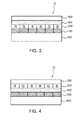
- FIGS. 1 to 5 are views illustrating multifunctional optical filters for a stereoscopic display device according to embodiments of the present invention.
- the optical filter of the present invention includes a 3D filter layer 100 and a color filter layer 200.
- the 3D filter layer 100 is used to realize a stereoscopic image by changing polarization states of right-eye image light and left-eye image light.
- the 3D filter layer 100 includes a first region 110 for adjusting a polarization state of the right-eye image light and a second region 120 for adjusting a polarization state of the left-eye image light.
- the 3D filter layer 100 includes a retardation film, which is patterned to allow the first region and the second region to have different respective phase difference values.
- the pattern of the 3D filter layer 100 may be striped or a grid shaped, but is not limited thereto.
- the 3D filter layer 100 includes forming a patterned liquid crystal alignment layer on a base film, coating a liquid crystal thereon, hardening it with ultraviolet rays to fix an alignment of the liquid crystal, and adjusting a polarization state.
- patterning the alignment layer may be performed through various methods. For example, one method includes alternately forming different respective liquid alignment layers in certain portions corresponding to the first region and the second region. Another method includes forming an alignment layer on an entire surface of a base film and forming another alignment layer overlapping on a portion corresponding to the second region on the alignment layer. Another method includes forming an alignment layer on an entire surface of a base film and projecting polarized light in different respective directions to the first region and the second region by using a photomask. A liquid crystal is aligned on the patterned alignment layer formed through the above methods, so as to realize the first region and the second region having different respective alignment directions.
- the color filter layer 200 serves to realize a color image and includes a RGB pattern.
- the RGB pattern of the color filter layer 200 is formed to correspond to the pattern of the 3D filter layer 100.
- the color filter layer 200 may be manufactured through a photolithography method using a color photosensitive material or a printing method. If the printing method is used, it may include an inkjet printing method or a gravure printing method.
- the 3D filter layer 100 and the color filter layer 200 may be stacked on a base film 300. At this point, their stacking order may vary. That is, as shown in FIG. 1 , the color filter layer 200 may be formed first on the base film 300 and then the 3D filter layer 100 may be formed thereon. As shown in FIG. 2 , the 3D filter layer 100 and the color filter layer 200 may be sequentially formed on the base film 300.
- the optical filter of the present invention may be manufactured through a method including forming the 3D filter layer 100 on the base film 300, forming the color filter layer 200 on another base film 500, and bonding the two base films 300 and 500 with an adhesive layer 400, besides a method of sequentially stacking the 3D filter layer 100 and the color filter layer 200 on one base film.
- the base films 300 and 500 may be made of a film having excellent light transmittance but are not especially limited thereto.
- the base films 300 and 500 may include a trichloroacetate film, a polyethylene terephthalate film, a cycloolefin copolymer film, a polyethylene naphthalate film, a celluose acetate film, a cellulose butyrate film, a cellulose propionate film, an ethyl cellulose film, an acrylic film, a polyvinyl alcohol film, and a polyethylene film.
- the optical filter may further include an adhesive layer 400 in addition to the 3D filter layer 100 and the color filter layer 200.
- the adhesive layer 400 may be disposed on the uppermost layer of the optical filter as shown in FIG. 3 and may be disposed between the 3D filter layer 100 and the color filter layer 200 as shown in FIG. 4 .
- the adhesive layer 400 When the adhesive layer 400 is formed on the uppermost layer of the optical filter, it is used to attach the optical filter to a display device.
- the adhesive layer 400 may include an acrylic adhesive, a rubber adhesive, and a silicon adhesive but an acrylic adhesive having excellent light transmittance may preferably be used for the adhesive layer 400.
- a release film 700 may be additionally attached to the adhesive layer 400 in order to prevent foreign substance attachment. The release film 700 is removed when the optical filter is attached to the display device. Then, the optical filter is attached to the display device.
- the adhesive layer 400 since the optical filter is detachable from the surface of the display device, the color filter layer 200 or the 3D filter layer 100 may be easily replaceable in the event it is damaged or malfunctions.
- the adhesive layer 400 serves as an ink reception layer, thereby improving ink dyeing power.
- a thickness of the adhesive layer 400 may be from about 5 ⁇ m to about 30 ⁇ m. If a thickness of the adhesive layer 400 is less than about 5 ⁇ m, accurate coating may be difficult and, if a thickness of the adhesive layer 400 is more than about 30 ⁇ m, an amount of an adhesive used may be increased.
- the optical filter of the present invention since the distance between the RGB pixels of the color filter layer 200 and the 3D filter layer 100 is relatively short, crosstalk is greatly reduced. Additionally, in a case of the optical filter of the present invention, since the color filter layer 200 and the 3D filter layer 100 are integrated into a single body, the RGB pattern and the 3D filter pattern may be formed to accurately correspond to each other and, as a result of this, a high quality 3D image may be realized.
- the optical filter of the present invention may be attached to an outer side of a display panel in an image display device.
- the display panel serves to generate a stereoscopic image.
- a panel formed of a glass material is manufactured and then a process for attaching the optical filter to the outer side of the display panel is performed.
- a typical high temperature process of more than about 200 °C used for an LCD panel manufacturing process or a typical high temperature process of more than about 500 °C used for a PDP manufacturing process is not performed, a film having a thermal resistance to more than about 200 °C is not used but a typical film is used.
- the typical film may include a trichloroacetate film, a polyethylene terephthalate film, a cycloolefin copolymer film, a polyethylene naphthalate film, a celluose acetate film, a cellulose butyrate film, a cellulose propionate film, an ethyl cellulose film, an acrylic film, a polyvinyl alcohol film, and a polyethylene film.
- These films are superior to a high-temperature-resistant polyimide film in aspects of transparency, pigmentation, and cost.
- a liquid crystal alignment layer used for a 3D filter layer or a pigmentation layer used for a color filter layer may be formed of a material having a low heat resistance.
- the optical filter of the present invention may be detachable from the substrate of the stereoscopic display device, when a defect or damage occurs in the color filter layer or the 3D filter layer, the optical filter may be easily repaired or replaceable, thereby facilitating manufacturing processes.
- a stereoscopic display device including the optical filter includes an image generating unit for generating an image light and an optical filter.
- the image generating unit may generate left-eye image light and right-eye image light and may be a typical display panel such as an LCD panel or a PDP panel.
- the optical filter since the optical filter includes a color filter, no color filter is required on the substrate of the display panel.
- FIG. 6 is a view of a stereoscopic display device according to an embodiment of the present invention.
- the stereoscopic display device of the present invention includes an upper substrate 610, a lower substrate 620, an image generating unit 600 formed of a liquid crystal cell 650 interposed between the upper substrate 610 and the lower substrate 620, and an optical filter 10 disposed at the outer side of the upper substrate 610 in the image generating unit.
- the upper substrate 610 and the lower substrate 620 may be formed of a material having excellent light transparency and, for example, may be include a glass or plastic substrate. Additionally, transparent electrodes 630 and 640 for applying power to the liquid crystal cell 650 are formed on facing surfaces of the upper substrate 610 and the lower substrate 620.
- the liquid crystal cell 650 serves to represent an on/off state and a grey state of a pixel by adjusting the transmittance of a polarized light and may have the same structure as a typical LCD device.
- the optical filter 10 is disposed on the outer side of the upper substrate 610 and includes a 3D filter layer 100, which is patterned into a first region 110 for adjusting a polarization state of a right-eye image and a second region 120 for adjusting a polarization state of a left-eye image, and a color filter layer 200 having a RGB pattern. Since detailed descriptions of the optical filter 10 are described above, overlapping descriptions will be omitted.
- a first alignment layer was comprehensively applied to a trichloro-acetate film, +45° polarized UV light was projected onto the result to harden the first alignment layer.
- a second alignment layer was applied to the first alignment layer in a parallel line shape and -45° polarized UV light was projected onto the result to harden the second alignment layer.
- a liquid crystal was coated on the result to harden it so that a 3D filter layer having a parallel line shape was formed.
- An acrylic adhesive was uniformly applied to the 3D filter layer with a 20 ⁇ m thickness to form an adhesive layer.
- a color ink was applied to the adhesive layer through an inkjet method to be aligned orthogonal to the lines of the 3D filter layer and the result was dried to form a color filter layer. As a result of this, an optical filter was finally manufactured.
- the optical film was attached to an LCD device to manufacture a stereoscopic display device.
- the optical filter was attached to an LCD device to manufacture a stereoscopic display device.
- embodiment 3 uses the same method as embodiment 2.
- a 3D filter layer in a parallel line shape was formed on a trichloro-acetate film.
- An acrylic adhesive was uniformly applied to a polyethylene terephthalate film with a 20 ⁇ m thickness and a color ink is applied through an inkjet method on the adhesive layer to be aligned orthogonal to the lines of the 3D filter layer and was then dried, in order to form a color filter layer.
- the optical filter was attached to an LCD device to manufacture a stereoscopic display device.
- a stereoscopic display device was manufactured through the same method as the embodiment 4.
- a single 3D filter which was not integrated with a color filter, was mounted on the external surface of an available LCD panel having a color filter between an upper substrate and a transparent electrode, in order to manufacture a stereoscopic display device.
- Pixel pitch about 0.54 mm
- multifunctional filter thickness about 0.2 mm
- Equation (1) XT L ( ⁇ ) and XT R ( ⁇ ) are defined as the following Equations (2) and (3).
- B L represents brightness when all pixels realizing right-eye image light and left-eye image light are in a black mode and the left-eye image light is observed at a viewing angle ⁇ through a left-eye lens unit of polarized glasses,
- L L is brightness when a pixel realizing right-eye image light is in a black mode, a pixel realizing left-eye image light is in a white mode, and the left-eye image light is observed at a viewing angle ⁇ through a left-eye lens unit of polarized glasses,
- R L is brightness when a pixel realizing right-eye image light is in a white mode, a pixel realizing left-eye image light is in a black mode, and the left-eye image light is observed at a viewing angle ⁇ through a left-eye lens unit of polarized glasses,
- B R represent brightness when all pixels realizing right-eye image light and left-eye image light are in a black mode and the right-eye image light are observed at a viewing angle ⁇ through a right-eye lens unit of polarized glasses,
- L R is brightness when a pixel realizing right-eye image light is in a black mode, a pixel realizing left-eye image light is in a white mode, and the right-eye image light is observed at a viewing angle ⁇ through a right-eye lens unit of polarized glasses, and
- R R is brightness when a pixel realizing right-eye image light is in a white mode, a pixel realizing left-eye image light is in a black mode, and the right-eye image light is observed at a viewing angle ⁇ through a right-eye lens unit of polarized glasses.
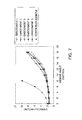
- FIG. 7 is a graph illustrating measured crosstalk rates.
- the measured values of the embodiments 1 to 5 show the same level within a measurement error. Through FIG. 7 , it is shown that the crosstalk rates of the embodiments 1 to 5 are significantly lower than that of the comparison example.
Landscapes
- Physics & Mathematics (AREA)
- General Physics & Mathematics (AREA)
- Optics & Photonics (AREA)
- Nonlinear Science (AREA)
- Chemical & Material Sciences (AREA)
- Crystallography & Structural Chemistry (AREA)
- Mathematical Physics (AREA)
- Polarising Elements (AREA)
- Testing, Inspecting, Measuring Of Stereoscopic Televisions And Televisions (AREA)
- Liquid Crystal (AREA)
- Stereoscopic And Panoramic Photography (AREA)
- Optical Filters (AREA)
Applications Claiming Priority (3)
| Application Number | Priority Date | Filing Date | Title |
|---|---|---|---|
| KR20100081047 | 2010-08-20 | ||
| KR1020110082354A KR101253206B1 (ko) | 2010-08-20 | 2011-08-18 | 복합 기능성 입체영상표시장치용 광학 필터 및 이를 포함하는 입체영상표시장치 |
| PCT/KR2011/006136 WO2012023832A2 (fr) | 2010-08-20 | 2011-08-19 | Filtre optique multifonction pour affichage d'image stéréoscopique, et afficheur d'image stéréoscopique comprenant ce filtre |
Publications (3)
| Publication Number | Publication Date |
|---|---|
| EP2607942A2 true EP2607942A2 (fr) | 2013-06-26 |
| EP2607942A4 EP2607942A4 (fr) | 2017-05-31 |
| EP2607942B1 EP2607942B1 (fr) | 2020-02-12 |
Family
ID=45839864
Family Applications (1)
| Application Number | Title | Priority Date | Filing Date |
|---|---|---|---|
| EP11818432.4A Active EP2607942B1 (fr) | 2010-08-20 | 2011-08-19 | Afficheur d'image stéréoscopique |
Country Status (7)
| Country | Link |
|---|---|
| US (2) | US8810743B2 (fr) |
| EP (1) | EP2607942B1 (fr) |
| JP (1) | JP2013541029A (fr) |
| KR (1) | KR101253206B1 (fr) |
| CN (1) | CN103154802B (fr) |
| TW (1) | TWI451133B (fr) |
| WO (1) | WO2012023832A2 (fr) |
Families Citing this family (8)
| Publication number | Priority date | Publication date | Assignee | Title |
|---|---|---|---|---|
| JP6321902B2 (ja) * | 2012-03-28 | 2018-05-09 | 大日本印刷株式会社 | 液晶表示装置 |
| KR101407927B1 (ko) | 2012-11-13 | 2014-06-17 | 주식회사 엘지화학 | 상변화 잉크 조성물을 이용하여 형성된 차광패턴을 포함하는 입체영상표시장치 |
| WO2014077579A1 (fr) * | 2012-11-13 | 2014-05-22 | 주식회사 엘지화학 | Dispositif d'affichage d'images tridimensionnelles ayant des motifs faisant écran à la lumière formés à l'aide de compositions d'encre à changement de phase |
| US9406253B2 (en) * | 2013-03-14 | 2016-08-02 | Broadcom Corporation | Vision corrective display |
| JP6375789B2 (ja) * | 2013-09-02 | 2018-08-22 | Jsr株式会社 | 液晶配向剤、液晶配向膜、液晶表示素子、位相差フィルム及びその製造方法 |
| KR102151608B1 (ko) * | 2013-09-02 | 2020-09-03 | 제이에스알 가부시끼가이샤 | 액정 배향제, 액정 배향막, 액정 표시 소자, 위상차 필름 및 그의 제조 방법, 중합체 그리고 화합물 |
| KR102075783B1 (ko) * | 2013-09-11 | 2020-02-10 | 엘지디스플레이 주식회사 | 3차원 영상 표시장치 |
| JP2018200350A (ja) * | 2017-05-25 | 2018-12-20 | 株式会社ジャパンディスプレイ | 表示パネル及び表示パネルの製造方法 |
Family Cites Families (33)
| Publication number | Priority date | Publication date | Assignee | Title |
|---|---|---|---|---|
| JPH0634969A (ja) * | 1992-07-21 | 1994-02-10 | Nikon Corp | 液晶テレビジョン装置 |
| JP3315048B2 (ja) * | 1996-01-23 | 2002-08-19 | シャープ株式会社 | 立体画像表示装置 |
| US6084647A (en) | 1996-11-22 | 2000-07-04 | Sharp Kabushiki Kaisha | Liquid crystal display device |
| JP3533057B2 (ja) * | 1996-11-22 | 2004-05-31 | シャープ株式会社 | 液晶表示装置 |
| JP3463846B2 (ja) * | 1997-02-14 | 2003-11-05 | シャープ株式会社 | 偏光素子およびその製造方法、並びに映像表示装置 |
| JPH10239641A (ja) | 1997-02-27 | 1998-09-11 | Sharp Corp | 偏光眼鏡および画像表示システム |
| JP3461680B2 (ja) | 1997-03-13 | 2003-10-27 | シャープ株式会社 | 光学素子の製造方法および画像表示装置 |
| GB2351866A (en) * | 1999-07-07 | 2001-01-10 | Sharp Kk | Stereoscopic display |
| US6961177B2 (en) | 2001-06-01 | 2005-11-01 | Sony Corporation | Stereoscopic image display apparatus, display apparatus, divided wave plate filter, plate-shared filter, and filter position adjusting mechanism attached to the display apparatus, aligning apparatus, filter position adjusting method, and filter aligning method |
| JP3901970B2 (ja) | 2001-09-04 | 2007-04-04 | ソニー株式会社 | 板状フィルター、表示装置、フィルターの位置合わせ方法、及びフィルターの位置合わせ装置 |
| US20040246407A1 (en) | 2001-10-12 | 2004-12-09 | Rohm Co., Ltd. | Liquid crystal display apparatus, mirror apparatus, and electric device having liquid crystal display apparatus |
| AU2003281711A1 (en) * | 2002-07-29 | 2004-02-16 | Sharp Kabushiki Kaisha | Substrate with parallax barrier layer, method for producing substrate with parallax barrier layer, and three-dimensional display |
| JP4074986B2 (ja) | 2002-09-06 | 2008-04-16 | ソニー株式会社 | 分割波長板フィルターの位置調整機構及び立体画像表示装置 |
| JP2004170693A (ja) * | 2002-11-20 | 2004-06-17 | Arisawa Mfg Co Ltd | 立体映像表示装置用位相差フィルタ |
| JP2004309868A (ja) * | 2003-04-08 | 2004-11-04 | Sony Corp | 撮像装置及び立体映像生成装置 |
| TWI256491B (en) | 2004-07-27 | 2006-06-11 | Pavonine Inc | Liquid crystal display device having thin polarizing film and thin phase retardation film |
| US7919795B2 (en) * | 2006-12-21 | 2011-04-05 | Samsung Electronics Co., Ltd. | Wire structure, method for fabricating wire, thin film transistor substrate, and method for fabricating the thin film transistor substrate |
| JP4259579B2 (ja) | 2007-01-16 | 2009-04-30 | セイコーエプソン株式会社 | 電気光学装置、電子機器、電気光学装置の駆動方法 |
| JP4201054B2 (ja) | 2007-02-16 | 2008-12-24 | 凸版印刷株式会社 | カラーフィルタ及びその製造方法及び液晶表示装置 |
| US20080304151A1 (en) | 2007-06-08 | 2008-12-11 | Arisawa Mfg. Co., Ltd. | Stereoscopic image display |
| TW200907225A (en) | 2007-08-15 | 2009-02-16 | Aeon Lighting Technology Inc | Light emitting diode (LED) road lamp |
| KR101311303B1 (ko) | 2007-09-11 | 2013-09-25 | 엘지디스플레이 주식회사 | 입체영상표시장치 |
| JP5125666B2 (ja) * | 2008-03-25 | 2013-01-23 | セイコーエプソン株式会社 | 液体吐出装置 |
| BRPI0911207B8 (pt) * | 2008-04-18 | 2022-10-11 | Dow Agrosciences Llc | 2-(fenil substituído)-6-hidróxi ou alcóxi-5-substituído-4-pirimidinacarboxilatos, composição herbicida, e método para controle de vegetação indesejável". |
| KR100939214B1 (ko) | 2008-06-12 | 2010-01-28 | 엘지디스플레이 주식회사 | 입체영상 표시장치의 정렬 시스템 및 방법 |
| KR101277223B1 (ko) * | 2008-07-09 | 2013-06-24 | 엘지디스플레이 주식회사 | 입체영상표시장치 |
| KR20110044292A (ko) | 2008-08-13 | 2011-04-28 | 다이니치 세이카 고교 가부시키가이샤 | 컬러 필터의 제조방법, 컬러 필터 기판 및 컬러 필터 |
| JP5236506B2 (ja) * | 2009-01-06 | 2013-07-17 | 日置電機株式会社 | 基板検査装置 |
| WO2010150693A1 (fr) | 2009-06-25 | 2010-12-29 | チッソ株式会社 | Film à retard composé de polyimide cristallin liquide photo-aligné et élément optique |
| JP2011075817A (ja) | 2009-09-30 | 2011-04-14 | Toppan Printing Co Ltd | 複屈折率制御インセルカラーフィルタ基板とその製造法及び、立体映像表示装置 |
| JP5213843B2 (ja) * | 2009-12-25 | 2013-06-19 | 日東電工株式会社 | 立体映像表示用位相差板、偏光素子およびそれらの製造方法、ならびに立体映像表示装置 |
| WO2011090355A2 (fr) * | 2010-01-22 | 2011-07-28 | (주)Lg화학 | Film adhesif collant destine a etre utilise dans le procede d'alignement de couches de photoalignement |
| JP2012022148A (ja) * | 2010-07-14 | 2012-02-02 | Nitto Denko Corp | 立体映像表示用位相差板、立体映像表示用偏光素子、および立体映像表示装置 |
-
2011
- 2011-08-18 KR KR1020110082354A patent/KR101253206B1/ko active Active
- 2011-08-19 TW TW100129752A patent/TWI451133B/zh active
- 2011-08-19 EP EP11818432.4A patent/EP2607942B1/fr active Active
- 2011-08-19 JP JP2013524802A patent/JP2013541029A/ja active Pending
- 2011-08-19 CN CN201180040384.4A patent/CN103154802B/zh active Active
- 2011-08-19 US US13/814,034 patent/US8810743B2/en active Active
- 2011-08-19 WO PCT/KR2011/006136 patent/WO2012023832A2/fr not_active Ceased
-
2014
- 2014-02-26 US US14/190,542 patent/US8964139B2/en active Active
Non-Patent Citations (1)
| Title |
|---|
| See references of WO2012023832A2 * |
Also Published As
| Publication number | Publication date |
|---|---|
| CN103154802A (zh) | 2013-06-12 |
| EP2607942A4 (fr) | 2017-05-31 |
| TWI451133B (zh) | 2014-09-01 |
| WO2012023832A3 (fr) | 2012-05-03 |
| US20140177048A1 (en) | 2014-06-26 |
| EP2607942B1 (fr) | 2020-02-12 |
| KR101253206B1 (ko) | 2013-04-16 |
| JP2013541029A (ja) | 2013-11-07 |
| US8964139B2 (en) | 2015-02-24 |
| US8810743B2 (en) | 2014-08-19 |
| TW201213866A (en) | 2012-04-01 |
| KR20120018090A (ko) | 2012-02-29 |
| US20130128164A1 (en) | 2013-05-23 |
| CN103154802B (zh) | 2016-01-06 |
| WO2012023832A2 (fr) | 2012-02-23 |
Similar Documents
| Publication | Publication Date | Title |
|---|---|---|
| US8964139B2 (en) | Multifunctional optical filter for stereoscopic display device and stereoscopic display device comprising the same | |
| US9110303B2 (en) | 3D display panel and method of manufacturing phase difference plate | |
| TWI449989B (zh) | 三維影像顯示裝置 | |
| CN103576408B (zh) | 立体显示装置 | |
| CN103686120B (zh) | 立体图像显示装置 | |
| TWI467238B (zh) | 立體影像顯示器及用於製造該立體影像顯示器的方法 | |
| WO2017156881A1 (fr) | Lentille à cristaux liquides et son procédé de fabrication, et dispositif d'affichage | |
| CN102914902B (zh) | 立体图像显示装置及其制造方法 | |
| CN102141703B (zh) | 一种具有相位延迟膜的偏光式3d液晶屏 | |
| CN103154801B (zh) | 显示装置 | |
| US20150192825A1 (en) | Liquid crystal panel and method for manufacturing the same | |
| US20100177175A1 (en) | Image Controllers and Display Devices | |
| TW201213897A (en) | Patterned retarder laminated composite polarizing plate and display apparatus using the same | |
| CN102645753A (zh) | 一种被动偏光式三维显示装置 | |
| CN101685210A (zh) | 可改变偏振化图像的偏光角度的图像处理系统及方法 | |
| KR101291806B1 (ko) | 입체영상 표시장치 | |
| KR101314402B1 (ko) | 표시 장치 | |
| CN104181737A (zh) | 立体显示器以及用于立体显示器的切换面板 | |
| TWI413814B (zh) | 具視差障壁層之偏光板及其製造方法、以及其應用之三次元顯示裝置 | |
| TR201809186T4 (tr) | Bir elektro-optik ve bir yönlendirme katmanına sahip bir otostereoskopik gösterge aparatına yönelik lentiküler araçlar ve bunları imal etmeye yönelik yöntem. | |
| KR101849177B1 (ko) | 입체 영상 표시장치 및 이의 제조방법 | |
| JP2015004725A (ja) | 画像表示装置 | |
| KR101708323B1 (ko) | 필름형 액정표시장치 제조방법 | |
| KR101972491B1 (ko) | 입체영상표시장치 및 그 제조방법 | |
| KR102113602B1 (ko) | 표시장치 및 이의 제조방법 |
Legal Events
| Date | Code | Title | Description |
|---|---|---|---|
| PUAI | Public reference made under article 153(3) epc to a published international application that has entered the european phase |
Free format text: ORIGINAL CODE: 0009012 |
|
| 17P | Request for examination filed |
Effective date: 20130128 |
|
| AK | Designated contracting states |
Kind code of ref document: A2 Designated state(s): AL AT BE BG CH CY CZ DE DK EE ES FI FR GB GR HR HU IE IS IT LI LT LU LV MC MK MT NL NO PL PT RO RS SE SI SK SM TR |
|
| DAX | Request for extension of the european patent (deleted) | ||
| A4 | Supplementary search report drawn up and despatched |
Effective date: 20170503 |
|
| RIC1 | Information provided on ipc code assigned before grant |
Ipc: G02B 5/20 20060101ALI20170425BHEP Ipc: G02B 27/22 20060101ALI20170425BHEP Ipc: H04N 13/04 20060101ALI20170425BHEP Ipc: G02F 1/13363 20060101ALI20170425BHEP Ipc: G02B 27/26 20060101AFI20170425BHEP |
|
| RAP1 | Party data changed (applicant data changed or rights of an application transferred) |
Owner name: LG CHEM, LTD. |
|
| REG | Reference to a national code |
Ref country code: DE Ref legal event code: R079 Ref document number: 602011064991 Country of ref document: DE Free format text: PREVIOUS MAIN CLASS: G02B0027260000 Ipc: H04N0013337000 |
|
| RIC1 | Information provided on ipc code assigned before grant |
Ipc: G02B 27/26 20060101ALI20190725BHEP Ipc: G02B 27/22 20180101ALI20190725BHEP Ipc: H04N 13/324 20180101ALI20190725BHEP Ipc: H04N 13/337 20180101AFI20190725BHEP Ipc: G02B 5/20 20060101ALI20190725BHEP |
|
| GRAP | Despatch of communication of intention to grant a patent |
Free format text: ORIGINAL CODE: EPIDOSNIGR1 |
|
| STAA | Information on the status of an ep patent application or granted ep patent |
Free format text: STATUS: GRANT OF PATENT IS INTENDED |
|
| INTG | Intention to grant announced |
Effective date: 20190905 |
|
| GRAS | Grant fee paid |
Free format text: ORIGINAL CODE: EPIDOSNIGR3 |
|
| GRAA | (expected) grant |
Free format text: ORIGINAL CODE: 0009210 |
|
| STAA | Information on the status of an ep patent application or granted ep patent |
Free format text: STATUS: THE PATENT HAS BEEN GRANTED |
|
| AK | Designated contracting states |
Kind code of ref document: B1 Designated state(s): AL AT BE BG CH CY CZ DE DK EE ES FI FR GB GR HR HU IE IS IT LI LT LU LV MC MK MT NL NO PL PT RO RS SE SI SK SM TR |
|
| REG | Reference to a national code |
Ref country code: GB Ref legal event code: FG4D |
|
| REG | Reference to a national code |
Ref country code: CH Ref legal event code: EP |
|
| REG | Reference to a national code |
Ref country code: AT Ref legal event code: REF Ref document number: 1233688 Country of ref document: AT Kind code of ref document: T Effective date: 20200215 |
|
| REG | Reference to a national code |
Ref country code: IE Ref legal event code: FG4D |
|
| REG | Reference to a national code |
Ref country code: DE Ref legal event code: R096 Ref document number: 602011064991 Country of ref document: DE |
|
| PG25 | Lapsed in a contracting state [announced via postgrant information from national office to epo] |
Ref country code: FI Free format text: LAPSE BECAUSE OF FAILURE TO SUBMIT A TRANSLATION OF THE DESCRIPTION OR TO PAY THE FEE WITHIN THE PRESCRIBED TIME-LIMIT Effective date: 20200212 Ref country code: NO Free format text: LAPSE BECAUSE OF FAILURE TO SUBMIT A TRANSLATION OF THE DESCRIPTION OR TO PAY THE FEE WITHIN THE PRESCRIBED TIME-LIMIT Effective date: 20200512 Ref country code: RS Free format text: LAPSE BECAUSE OF FAILURE TO SUBMIT A TRANSLATION OF THE DESCRIPTION OR TO PAY THE FEE WITHIN THE PRESCRIBED TIME-LIMIT Effective date: 20200212 |
|
| REG | Reference to a national code |
Ref country code: LT Ref legal event code: MG4D |
|
| REG | Reference to a national code |
Ref country code: NL Ref legal event code: MP Effective date: 20200212 |
|
| PG25 | Lapsed in a contracting state [announced via postgrant information from national office to epo] |
Ref country code: HR Free format text: LAPSE BECAUSE OF FAILURE TO SUBMIT A TRANSLATION OF THE DESCRIPTION OR TO PAY THE FEE WITHIN THE PRESCRIBED TIME-LIMIT Effective date: 20200212 Ref country code: GR Free format text: LAPSE BECAUSE OF FAILURE TO SUBMIT A TRANSLATION OF THE DESCRIPTION OR TO PAY THE FEE WITHIN THE PRESCRIBED TIME-LIMIT Effective date: 20200513 Ref country code: LV Free format text: LAPSE BECAUSE OF FAILURE TO SUBMIT A TRANSLATION OF THE DESCRIPTION OR TO PAY THE FEE WITHIN THE PRESCRIBED TIME-LIMIT Effective date: 20200212 Ref country code: IS Free format text: LAPSE BECAUSE OF FAILURE TO SUBMIT A TRANSLATION OF THE DESCRIPTION OR TO PAY THE FEE WITHIN THE PRESCRIBED TIME-LIMIT Effective date: 20200612 Ref country code: SE Free format text: LAPSE BECAUSE OF FAILURE TO SUBMIT A TRANSLATION OF THE DESCRIPTION OR TO PAY THE FEE WITHIN THE PRESCRIBED TIME-LIMIT Effective date: 20200212 Ref country code: BG Free format text: LAPSE BECAUSE OF FAILURE TO SUBMIT A TRANSLATION OF THE DESCRIPTION OR TO PAY THE FEE WITHIN THE PRESCRIBED TIME-LIMIT Effective date: 20200512 |
|
| PG25 | Lapsed in a contracting state [announced via postgrant information from national office to epo] |
Ref country code: NL Free format text: LAPSE BECAUSE OF FAILURE TO SUBMIT A TRANSLATION OF THE DESCRIPTION OR TO PAY THE FEE WITHIN THE PRESCRIBED TIME-LIMIT Effective date: 20200212 |
|
| PG25 | Lapsed in a contracting state [announced via postgrant information from national office to epo] |
Ref country code: ES Free format text: LAPSE BECAUSE OF FAILURE TO SUBMIT A TRANSLATION OF THE DESCRIPTION OR TO PAY THE FEE WITHIN THE PRESCRIBED TIME-LIMIT Effective date: 20200212 Ref country code: RO Free format text: LAPSE BECAUSE OF FAILURE TO SUBMIT A TRANSLATION OF THE DESCRIPTION OR TO PAY THE FEE WITHIN THE PRESCRIBED TIME-LIMIT Effective date: 20200212 Ref country code: CZ Free format text: LAPSE BECAUSE OF FAILURE TO SUBMIT A TRANSLATION OF THE DESCRIPTION OR TO PAY THE FEE WITHIN THE PRESCRIBED TIME-LIMIT Effective date: 20200212 Ref country code: LT Free format text: LAPSE BECAUSE OF FAILURE TO SUBMIT A TRANSLATION OF THE DESCRIPTION OR TO PAY THE FEE WITHIN THE PRESCRIBED TIME-LIMIT Effective date: 20200212 Ref country code: SM Free format text: LAPSE BECAUSE OF FAILURE TO SUBMIT A TRANSLATION OF THE DESCRIPTION OR TO PAY THE FEE WITHIN THE PRESCRIBED TIME-LIMIT Effective date: 20200212 Ref country code: EE Free format text: LAPSE BECAUSE OF FAILURE TO SUBMIT A TRANSLATION OF THE DESCRIPTION OR TO PAY THE FEE WITHIN THE PRESCRIBED TIME-LIMIT Effective date: 20200212 Ref country code: PT Free format text: LAPSE BECAUSE OF FAILURE TO SUBMIT A TRANSLATION OF THE DESCRIPTION OR TO PAY THE FEE WITHIN THE PRESCRIBED TIME-LIMIT Effective date: 20200705 Ref country code: DK Free format text: LAPSE BECAUSE OF FAILURE TO SUBMIT A TRANSLATION OF THE DESCRIPTION OR TO PAY THE FEE WITHIN THE PRESCRIBED TIME-LIMIT Effective date: 20200212 Ref country code: SK Free format text: LAPSE BECAUSE OF FAILURE TO SUBMIT A TRANSLATION OF THE DESCRIPTION OR TO PAY THE FEE WITHIN THE PRESCRIBED TIME-LIMIT Effective date: 20200212 |
|
| REG | Reference to a national code |
Ref country code: DE Ref legal event code: R097 Ref document number: 602011064991 Country of ref document: DE |
|
| REG | Reference to a national code |
Ref country code: AT Ref legal event code: MK05 Ref document number: 1233688 Country of ref document: AT Kind code of ref document: T Effective date: 20200212 |
|
| PLBE | No opposition filed within time limit |
Free format text: ORIGINAL CODE: 0009261 |
|
| STAA | Information on the status of an ep patent application or granted ep patent |
Free format text: STATUS: NO OPPOSITION FILED WITHIN TIME LIMIT |
|
| 26N | No opposition filed |
Effective date: 20201113 |
|
| PG25 | Lapsed in a contracting state [announced via postgrant information from national office to epo] |
Ref country code: AT Free format text: LAPSE BECAUSE OF FAILURE TO SUBMIT A TRANSLATION OF THE DESCRIPTION OR TO PAY THE FEE WITHIN THE PRESCRIBED TIME-LIMIT Effective date: 20200212 Ref country code: IT Free format text: LAPSE BECAUSE OF FAILURE TO SUBMIT A TRANSLATION OF THE DESCRIPTION OR TO PAY THE FEE WITHIN THE PRESCRIBED TIME-LIMIT Effective date: 20200212 |
|
| PG25 | Lapsed in a contracting state [announced via postgrant information from national office to epo] |
Ref country code: PL Free format text: LAPSE BECAUSE OF FAILURE TO SUBMIT A TRANSLATION OF THE DESCRIPTION OR TO PAY THE FEE WITHIN THE PRESCRIBED TIME-LIMIT Effective date: 20200212 Ref country code: SI Free format text: LAPSE BECAUSE OF FAILURE TO SUBMIT A TRANSLATION OF THE DESCRIPTION OR TO PAY THE FEE WITHIN THE PRESCRIBED TIME-LIMIT Effective date: 20200212 |
|
| PG25 | Lapsed in a contracting state [announced via postgrant information from national office to epo] |
Ref country code: MC Free format text: LAPSE BECAUSE OF FAILURE TO SUBMIT A TRANSLATION OF THE DESCRIPTION OR TO PAY THE FEE WITHIN THE PRESCRIBED TIME-LIMIT Effective date: 20200212 |
|
| REG | Reference to a national code |
Ref country code: CH Ref legal event code: PL |
|
| PG25 | Lapsed in a contracting state [announced via postgrant information from national office to epo] |
Ref country code: LU Free format text: LAPSE BECAUSE OF NON-PAYMENT OF DUE FEES Effective date: 20200819 Ref country code: LI Free format text: LAPSE BECAUSE OF NON-PAYMENT OF DUE FEES Effective date: 20200831 Ref country code: CH Free format text: LAPSE BECAUSE OF NON-PAYMENT OF DUE FEES Effective date: 20200831 |
|
| REG | Reference to a national code |
Ref country code: BE Ref legal event code: MM Effective date: 20200831 |
|
| PG25 | Lapsed in a contracting state [announced via postgrant information from national office to epo] |
Ref country code: IE Free format text: LAPSE BECAUSE OF NON-PAYMENT OF DUE FEES Effective date: 20200819 Ref country code: BE Free format text: LAPSE BECAUSE OF NON-PAYMENT OF DUE FEES Effective date: 20200831 |
|
| PG25 | Lapsed in a contracting state [announced via postgrant information from national office to epo] |
Ref country code: TR Free format text: LAPSE BECAUSE OF FAILURE TO SUBMIT A TRANSLATION OF THE DESCRIPTION OR TO PAY THE FEE WITHIN THE PRESCRIBED TIME-LIMIT Effective date: 20200212 Ref country code: MT Free format text: LAPSE BECAUSE OF FAILURE TO SUBMIT A TRANSLATION OF THE DESCRIPTION OR TO PAY THE FEE WITHIN THE PRESCRIBED TIME-LIMIT Effective date: 20200212 Ref country code: CY Free format text: LAPSE BECAUSE OF FAILURE TO SUBMIT A TRANSLATION OF THE DESCRIPTION OR TO PAY THE FEE WITHIN THE PRESCRIBED TIME-LIMIT Effective date: 20200212 |
|
| PG25 | Lapsed in a contracting state [announced via postgrant information from national office to epo] |
Ref country code: MK Free format text: LAPSE BECAUSE OF FAILURE TO SUBMIT A TRANSLATION OF THE DESCRIPTION OR TO PAY THE FEE WITHIN THE PRESCRIBED TIME-LIMIT Effective date: 20200212 Ref country code: AL Free format text: LAPSE BECAUSE OF FAILURE TO SUBMIT A TRANSLATION OF THE DESCRIPTION OR TO PAY THE FEE WITHIN THE PRESCRIBED TIME-LIMIT Effective date: 20200212 |
|
| PGFP | Annual fee paid to national office [announced via postgrant information from national office to epo] |
Ref country code: DE Payment date: 20250721 Year of fee payment: 15 |
|
| PGFP | Annual fee paid to national office [announced via postgrant information from national office to epo] |
Ref country code: GB Payment date: 20250722 Year of fee payment: 15 |
|
| PGFP | Annual fee paid to national office [announced via postgrant information from national office to epo] |
Ref country code: FR Payment date: 20250725 Year of fee payment: 15 |