EP2608497A1 - Elektronische Vorrichtung mit modifizierbarem Ausgabeparameter - Google Patents
Elektronische Vorrichtung mit modifizierbarem Ausgabeparameter Download PDFInfo
- Publication number
- EP2608497A1 EP2608497A1 EP11195131.5A EP11195131A EP2608497A1 EP 2608497 A1 EP2608497 A1 EP 2608497A1 EP 11195131 A EP11195131 A EP 11195131A EP 2608497 A1 EP2608497 A1 EP 2608497A1
- Authority
- EP
- European Patent Office
- Prior art keywords
- sound
- electronic device
- sensor
- output
- output parameter
- Prior art date
- Legal status (The legal status is an assumption and is not a legal conclusion. Google has not performed a legal analysis and makes no representation as to the accuracy of the status listed.)
- Granted
Links
Images





Classifications
-
- H—ELECTRICITY
- H04—ELECTRIC COMMUNICATION TECHNIQUE
- H04M—TELEPHONIC COMMUNICATION
- H04M19/00—Current supply arrangements for telephone systems
- H04M19/02—Current supply arrangements for telephone systems providing ringing current or supervisory tones, e.g. dialling tone or busy tone
- H04M19/04—Current supply arrangements for telephone systems providing ringing current or supervisory tones, e.g. dialling tone or busy tone the ringing-current being generated at the substations
- H04M19/042—Current supply arrangements for telephone systems providing ringing current or supervisory tones, e.g. dialling tone or busy tone the ringing-current being generated at the substations with variable loudness of the ringing tone, e.g. variable envelope or amplitude of ring signal
- H04M19/044—Current supply arrangements for telephone systems providing ringing current or supervisory tones, e.g. dialling tone or busy tone the ringing-current being generated at the substations with variable loudness of the ringing tone, e.g. variable envelope or amplitude of ring signal according to the level of ambient noise
-
- H—ELECTRICITY
- H04—ELECTRIC COMMUNICATION TECHNIQUE
- H04M—TELEPHONIC COMMUNICATION
- H04M1/00—Substation equipment, e.g. for use by subscribers
- H04M1/72—Mobile telephones; Cordless telephones, i.e. devices for establishing wireless links to base stations without route selection
- H04M1/724—User interfaces specially adapted for cordless or mobile telephones
- H04M1/72448—User interfaces specially adapted for cordless or mobile telephones with means for adapting the functionality of the device according to specific conditions
- H04M1/72454—User interfaces specially adapted for cordless or mobile telephones with means for adapting the functionality of the device according to specific conditions according to context-related or environment-related conditions
-
- H—ELECTRICITY
- H04—ELECTRIC COMMUNICATION TECHNIQUE
- H04M—TELEPHONIC COMMUNICATION
- H04M2250/00—Details of telephonic subscriber devices
- H04M2250/12—Details of telephonic subscriber devices including a sensor for measuring a physical value, e.g. temperature or motion
Definitions
- the instant disclosure relates to an electronic device. More specifically, the instant disclosure relates to an electronic device and method for modifying an output parameter of the electronic device based on at least a received sound.
- Electronic devices are capable of providing a variety of different information to an operator.
- an electronic device can be enabled for providing telephonic services, internet services, playing music, playing videos, and data services, such as text messaging and email messaging.
- the electronic device can be carried by the operator in a variety of different manners for example in a holster, in a pocket, in a briefcase, in a bag, and in a purse.
- the electronic device can be used in a variety of different settings, for example quite settings, loud settings, airplane settings, indoors, outdoors, day time, and night time.
- An electronic device can provide communication notifications, such as visual display, ring tones, and vibrational alerts.
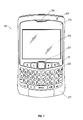
- Figure 1 is a front view of an electronic device in accordance with an exemplary implementation
- Figure 2 is a rear view of an electronic device in accordance with an exemplary implementation
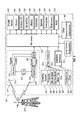
- Figure 3 is a block diagram representing an electronic device in accordance with an exemplary implementation
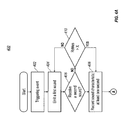
- Figure 4A - 4C is a schematic view of a flowchart illustrating a method for execution on an electronic device to modify an output parameter in accordance with an exemplary implementation
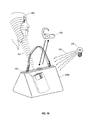
- Figure 5A is overview diagram of an electronic device being used in an environment having ambient noise
- Figure 5B is overview diagram of an electronic device within an open container which obstructs audio notifications from the electronic device
- Figure 5C is overview diagram of an electronic device within a closed container obstructs audio notifications from the electronic device
- Figures 6A is overview diagram of an electronic device in an environment in accordance with an exemplary implementation
- Figure 6B is overview diagram of an electronic device operating in an environment having ambient noise which interferes with audio notifications in accordance with an exemplary implementation
- Figure 6C is overview diagram of an electronic device providing a modified notification in accordance with an exemplary implementation
- Figure 7A is overview diagram of an electronic device operating in a lighted environment in accordance with an exemplary implementation.
- Coupled is defined as connected, whether directly or indirectly through intervening components, and is not necessarily limited to physical connections.
- communicatively coupled is defined as connected, whether directly or indirectly through intervening components, is not necessarily limited to a physical connection, and allows for the transfer of data.
- electronic device is defined as any device that includes a processor.
- the electronic device generally includes its own power source (such as a rechargeable battery), although in some embodiments, the electronic device can receive power from an external source, such as an adapter or a charger.
- the electronic device can be a handheld wireless communication device, handheld wired communication device, personal digital assistant (PDA), cellular phone, smart phone, MP3 player, mobile station such as a cellular telephones smart telephone, portable gaming systems, portable audio and video players, electronic writing or typing tablets, mobile messaging devices, and portable computers (such as tablet computers or laptop computers).
- PDA personal digital assistant
- cellular phone smart phone
- MP3 player mobile station
- a cellular telephones smart telephone portable gaming systems
- portable audio and video players electronic writing or typing tablets
- mobile messaging devices and portable computers (such as tablet computers or laptop computers).
- portable computers such as tablet computers or laptop computers.
- RAM Random Access Memory
- ROM Read-Only Memory
- flash ferromagnetic, phase-change memory, and other non-transitory memory technologies.
- holster is used herein for convenience, and may include a variety of devices that receive, hold or carry electronic devices, including a conventional holster, a briefcase, a laptop bag, a backpack, a laptop sleeve, an electronic pad cover, a carrying case, a handbag, or other carrier.
- holster sensor is a sensor that is used to detect if an electronic device is within the holster.
- the holster sensor can include one or more of a magnetic sensor, a capacitive sensor, a radio-frequency identification (RFID) sensor, a proximity sensor, or any other sensor that can determine if an electronic device is in a holster.
- RFID radio-frequency identification
- notifications include a display, a sound, a vibration, and a light.
- ringtone refers to a sound emitted from an electronic device to provide notification to the user of an event, which can be receipt of a phone call, receipt of a text message, transmission of a text message, transmission of an email, receipt of an email, an alarm, or another indication that an event has occurred on or at the electronic device.
- the ringtone can be any sound that is emitted from the electronic device that provides notification to the operator.
- the term “ambient area” refers to the area surrounding an object, such as the electronic device, that influences the reception or perception of sound. Ambient area can also be called the environment.
- ambient noise refers to sound in the ambient area.
- a “wireless communication” means communication that occurs without wires using electromagnetic radiation.
- the electronic device 100 comprises a lighted display 322 located above the keyboard 332 constituting a user input and suitable for accommodating textual input to the electronic device 100.
- the front face 270 of the electronic device 100 can have a navigation row 70.
- the electronic device 100 can include a notification indicator 210, such as a light emitting diode (LED) or other light source that provides visual notification to electronic device 100 operator.
- the notification indicator 210 can be configured to change colors and frequency to communicate different notifications to the operator.
- the electronic device 100 is of unibody construction, also known as a "candy-bar" design. In alternate implementations, the electronic device 100 can be a "clamshell" or a "slider” design.
- navigation tool 227 can be above the keyboard 332 and below the display screen 322; here, the navigation tool 227 can avoid interference during keyboarding and does not block the operator's view of the display screen 322 during use.
- the electronic device 100 can also include a camera 323 to allow the user to take electronic photographs which can be referred to as photos or pictures.
- the camera 323 can also be enabled to allow for video recording.
- the camera 323 can include a lens 325, a photodetector such as a Charge Coupled Device (CCD) for light/image detection (not shown), as well as a flash assembly 327, such as an LED, for emitting light.
- the photodetector can be a complementary metal oxide semiconductor (CMOS).
- CMOS complementary metal oxide semiconductor
- the camera 323 can be communicatively coupled with a processor module.
- the electronic device 100 can include an ambient light sensor 329 for sensing and detecting ambient light.
- the separate ambient light sensor 329 can be configured to sense at least one of a range of light levels and wavelengths. While both the camera 323 and the ambient light sensor 329 are illustrated it is appreciated that the electronic device 100 according to the present disclosure can only have one of a camera 323 or an ambient light sensor 329. When provided with only a camera 323, the camera 323 can be configured to obtain ambient light characteristics which include at least one of light level and light wavelengths.
- FIG. 3 is an exemplarily block diagram of an exemplarily electronic device 100 according to the present disclosure. It will be appreciated that additional elements and modifications can be necessary to make the electronic device 100 work in particular network environments.
- the electronic device 100 includes a processor module 338 that controls the operation of the electronic device 100.
- the processor module 338 can include one or more processors, each of which can be a microprocessor.
- a communication subsystem 311 can perform communication transmission and reception with one or more wireless networks 319.
- the processor module 338 can be communicatively coupled to an auxiliary input/output (I/O) subsystem 328 which can be communicatively coupled to the electronic device 100.
- I/O auxiliary input/output
- the processor module 338 can be communicatively coupled to a serial port (for example, a Universal Serial Bus port) 330 that facilitates communication with other devices or systems via the serial port 330.
- a display 322 can be communicatively coupled to processor module 338 to display information to an operator of the electronic device 100.
- the electronic device 100 is equipped with a keyboard 332, which may be physical or virtual, the keyboard 332 can be communicatively coupled to the processor module 338.
- the electronic device 100 can include a speaker 334, a microphone 336, random access memory 326 (RAM), and flash memory 324, all of which may be communicatively coupled to the processor module 338.
- a photosensor 331 can be optionally included.
- the photosensor 331 can be either a standalone device or incorporated into the camera.
- the photosensor 331 can be communicatively coupled to the processor module 338.
- the photosensor can be a camera 323 or an ambient light sensor 329.
- the electronic device 100 can include a holster sensor 335 that is communicatively coupled to the processor module 338.
- the holster sensor 335 can determine whether the electronic device is within a holster.
- the electronic device 100 can send and receives signal from an electronic communication service.
- Examples of communication systems enabled for two-way communication can include, but are not limited to, the General Packet Radio Service (GPRS) network, the Universal Mobile Telecommunication Service (UMTS) network, the Enhanced Data for Global Evolution (EDGE) network, the Code Division Multiple Access (CDMA) network, High-Speed Packet Access (HSPA) networks, Universal Mobile Telecommunication Service Time Division Duplexing (UMTS-TDD), Ultra Mobile Broadband (UMB) networks, Worldwide Interoperability for Microwave Access (WiMAX), and other networks that can be used for data and voice, or just data or voice.
- GPRS General Packet Radio Service
- UMTS Universal Mobile Telecommunication Service
- EDGE Enhanced Data for Global Evolution
- CDMA Code Division Multiple Access
- UMTS-TDD Universal Mobile Telecommunication Service Time Division Duplexing
- UMB Ultra Mobile Broadband
- WiMAX Worldwide Interoperability for Microwave Access
- the electronic device 100 can require a unique identifier to enable the electronic device 100 to transmit and receive signals from the communication network 319. Other systems may not require such identifying information.
- GPRS, UMTS, and EDGE use a Subscriber Identity Module (SIM) in order to allow communication with the communication network 319.
- SIM Subscriber Identity Module
- RUIM Removable User Identity Module
- the RUIM and SIM card can be used in a multitude of different electronic devices 100.
- the electronic device 100 can operate some features without a SIM/RUIM card, but a SIM/RUIM card is necessary for communication with the network 319.
- a SIM/RUIM interface 344 located within the electronic device 100 can allow for removal or insertion of a SIM/RUIM card (not shown).
- the SIM/RUIM card can feature memory and holds key configurations 351, and other information 353 such as identification and subscriber related information. With a properly enabled electronic device 100, two-way communication between the electronic device 100 and communication network 319 can be possible.
- the two-way communication enabled electronic device 100 is able to both transmit and receive information from the communication network 319.
- the transfer of communication can be from the electronic device 100 or to the electronic device 100.
- the electronic device 100 in the presently described exemplary embodiment can be equipped with an integral or internal antenna 318 for transmitting signals to the communication network 319.
- the electronic device 100 in the presently described exemplary embodiment can be equipped with another antenna 316 for receiving communication from the communication network 319.
- These antennae (316, 318) in another exemplary embodiment can be combined into a single antenna (not shown).
- the antenna or antennae (316, 318) in another embodiment can be externally mounted on the electronic device 100.
- the electronic device 100 can include a communication subsystem 311. As is understood in the art, this communication subsystem 311 can support the operational needs of the electronic device 100.
- the subsystem 311 can include a transmitter 314 and receiver 312 including the associated antenna or antennae (316, 318) as described above, local oscillators (LOs) 313, and a processing module 320 which in the presently described exemplary embodiment can be a digital signal processor (DSP) 320.
- DSP digital signal processor
- Communication by the electronic device 100 with one or more wireless networks 319 can be any type of communication that both the one or more wireless networks 319 and electronic device 100 are enabled to transmit, receive and process. In general, these can be classified as voice and data.
- Voice communication generally refers to communication in which signals for audible sounds are transmitted by the electronic device 100 through the one or more communication networks 319.
- Data generally refers to all other types of communication that the electronic device 100 is capable of performing within the constraints of the one or more wireless networks 319.
- FIG. 4A - 4C illustrates an exemplary method of operating the electronic device 100.
- the exemplary method is provided by way of example, as there are a variety of ways to carry out the method. Some steps of the method can be omitted in at least one implementation. In one or more implementations, the method can be performed by the processor module 338 of the electronic device 100. The methods can be executed or otherwise performed by one or a combination of various systems. The methods described below can be carried out using the electronic device and communication network shown in Figures 1-3 by way of example, and various elements of these figures are referenced in explaining the exemplary method. Each block show in Figures 4A-4C represents one or more processes, methods, or subroutines, carried out in the exemplary method. While the majority of examples are described herein in relation to a call or a message, the present disclosure can be applied without receipt of a call or message.
- the method 400 can begin at block 402.
- a second sound is received.
- the second sound can be based at least in part on the first sound.
- the second sound can also include ambient noise such as noise from vehicles, chatter in a dinner, airport sounds, and other sounds which are in the ambient area.
- the portion of the second sound that is based at least in part on the first sound can include a reflection or attenuation of the first sound.
- the reception of the second sound can be received by at least one sound receiving device, such as a speaker 334, of the electronic device 100.
- the electronic device 100 can repeat the emission of the first sound for a predetermined number times (X) (see block 410).
- the number of times (X) that the method 400 repeats emitting the first sound and receiving the second sound can be a predetermined number of times (X).
- the predetermined number can be three. In other instances, the predetermined number can be between three and ten or the predetermined number can be two.
- the method can omit the re-emission of the first sound and execute a different routine.
- the different routine can include varying the frequency, amplitude or a combination thereof of the first sound so that a second sound can be received by the electronic device.
- the different routine can be one in which the method does not repeat the emission of the first sound, but rather uses different input for example input from one or more sensors.
- the first sound can be varied as the emission of the first sound is repeated. For example, on subsequent emissions of the first sound, the volume, frequency or amplitude of the sound can be varied.
- the method 400 determines whether the electronic device 100 has a paired device.
- the determination of whether the electronic device 100 has a paired device can be through a sensor that indicates whether the device is paired. As indicated above, this sensor can be either a hardware or software sensor. If it is determined that the electronic device 100 has a paired device, then the method 400 can determine if the paired device is enabled (block 430). If the paired device is enabled, a further determination can be made as to the use of the modification of the output parameter can be made (block 432). For example, the operator can enable modification of the output parameter regardless of whether at least one paired device is communicatively coupled to the electronic device 100.
- the operator can disable modification of the output parameter when the at least one paired device is communicatively coupled to the electronic device 100. In yet another example, the operator can enable modification of the output parameter when the at least one paired device is communicatively coupled to the electronic device 100.
- the pairing can also include a security feature, which only allows devices to be paired if certain security standards are satisfied. For instance, the pairing of the devices can require that a security key be exchanged by at least one device or that a security key is exchanged by both devices. Furthermore, it is possible to only allow pairing after a device password has been input. This allows for communication between the paired devices to be conducted without other devices being able to receive the communications.
- a third sound is received.
- the third sound can include ambient noise.
- the receiving of the third sound can allow method 400 to determine the difference between the second sound and the third sound so as to better distinguish the difference between a portion of the second sound that is based upon the first sound and the ambient noise in the second sound.
- the difference can be determined using different sample sizes and spacing between the receiving of the second sound and receiving of the third sound.
- the receiving of the third sound can occur before the emission of the second sound.
- the receiving of the third sound can be before the emission of the first sound and after the reception of the second sound.
- the ambient noise can be determined so as to allow for variations of the ambient noise.
- the duration of the reception of the third sound can be varied to accommodate changes in the ambient sound.
- the ambient sound can be characterized by one of the average ambient noise, average plus high points of the ambient noise, and average with frequencies of the first sound.
- At block 426 at least one output parameter is modified.
- the modification of the at least one output parameter can be based upon the analysis of block 424.
- the modification of the output parameter is in response to the comparison of the first sound and the second sound and the output data from the at least one sensor.
- an appropriate notification is emitted.
- the appropriate notification is based upon the output parameter.
- the appropriate notification can be emitted by the at least one notification device of the electronic device.
- the appropriate notification can be a ringtone that has been modified in light of the above method.
- the ringtone can be modified such that at least one of the frequency, amplitude, signal strength, signal quality, duration, or some combination thereof is changed compared to the standard ringtone of the electronic device.
- the appropriate notification can further include a notification light that is steady or flashes at predetermined intervals.
- the notification light can change colors. The notification light can be provided when a determination that the electronic device 100 is not in a holster and is in a dark environment.
- FIG. 5A-5C an electronic device 100 and an operator 502 are illustrated.
- the electronic device 100 is operated in an environment that has a high level of ambient noise 505.
- Figure 5A also illustrates the ambient noise sound waves 504.
- the electronic device 100 receives an incoming communication illustrated by 506, the electronic device 100 can generate an output parameter which is output via a notification device.
- the output parameter causes a speaker to output sound 508.
- the electronic device receives the incoming communication which in at least one embodiment can be a trigger even to cause the processor to execute the method 400 as described above.
- the method 400 as described above.
- the present technology can also be implemented to allow an operator 502 to hear a ringtone when the electronic device 100 is within an obstructing, isolating or muffling environment such as a purse illustrated in Figures 5B and 5C .
- the purse 509a is in an open configuration.
- the pursue 509a allows the some of the emitted ringtone sound 508 to escape the purse, but the ringtone sound 508 can be muffled, attenuated, muted, or otherwise modified.
- the operator may not hear the ringtone sound 508 and thereby inadvertently miss notification of the incoming communication 506.
- Figure 5C illustrates another example of where the ringtone sound 508 is muffled, attenuated, muted, or otherwise modified.
- the electronic device 100 is located within a closed purse 509b.
- the purse 509b is closed, the ringtone sound 508 emitted by the device can be further muffled, attenuated, muted, or otherwise modified as compared to the open pursue 509a. While some portion of the ringtone sound 508 can be amplified by the open purse 509a or the closed purse 509b, it is expected that most of the sounds will be muffled, attenuated, muted, or otherwise modified.
- the electronic device 100 can be concealed within other containers such as a briefcase, backpack, and carrying case. Additionally and alternatively, if the electronic device 100 is disposed in an environment that is quiet, the preset ringer or signal volume can be too high and irritate the operator 502 or others in the nearby vicinity.
- electronic device 100 can be configured to be received in holster 102 and can include a sensor (not shown) for determining whether the electronic device is disposed in the holster 102.
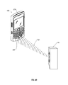
- Electronic device 100 can also be configured to communicate with a paired device 104, such as a BLUETOOTH ® headset. While the paired device 104 is illustrated as a BLUETOOTH ® headset, the paired device 104 can be a variety of different devices.
- the paired device 104 can be a keyboard, a display, a stereo, a car navigation unit, a radio, a laptop, another electronic device, and a desktop computer.
- the paired device 104 is shown as being communicatively coupled to the electronic device 100 via a short range wireless communications. In other implementations, the paired device 104 can be communicatively coupled to the electronic device 100 via a wired connection. In yet other embodiments, the paired device 104 can be communicatively coupled to the electronic device 100 via a combination of wireless and wired technologies
- the first sound 108 can be a ringtone sound, a low-pitch sound, a preset tone, a high-pitch sound, a sound above the range of average human hearing, a sound below the range of average human hearing, or other sound which can be detected by a sound receiving device.
- the emission of the first sound 108 can be at a predetermined time or based upon an event at the electronic device 100.
- the triggering event occurring at the electronic device 100 can include receipt of an incoming communication such as a telephone call, a text message, a multi-media message, a chat message, a voice-over-ip telephone call, or other message.
- the triggering event can also include an application specific event such a game alert message, a navigation communication, or an alarm.
- the emitted first sound 108 can further be a sound that is generated in response to any of these triggering events.
- the electronic device 100 can also be further provided with other notification devices that provide for other notifications.
- a notification light can be included or a display can present notification icons, and messages to an operator.
- the notification device can also include a vibrator as described above.
- the operator 502 can select the acceptable emissions of the first sound 108.
- the emission of first sound 108 can be undesirable and the operator 502 can prohibit the emission of the first sound 108 from the electronic device 100.
- the user can select an automatic emission of the first sound 108, where the first sound 108 is selected as described herein.
- the operator 502 can select the first sound 108 that can be emitted. For example, in some environments, it might be desirable to limit the first sound 108 to a given pitch, frequency or other measure. Additionally, the operator can limit the duration of the first sound 108.
- the above controls can be implemented using a dialog box on the display of the electronic device 100. In other embodiments, the user controls can be contained within a specific application running on the electronic device 100.
- the second sound 110 can include other sounds such as ambient noise.
- the electronic device 100 can modify an output parameter of the electronic device 100 in response to the comparison of the first sound 108 and the second sound 110. While in at least one embodiment, the modification of the output parameter of the electronic device 100 is in response to the comparison of the first sound 108 and the second sound 110, the modification can be based on other types of analysis that can include this analysis and additional analysis or not include this analysis and include other analysis.
- the technology can also record the second sound 110 received at the at least one sound receiving device.
- the recording of the second sound 110 can be for a predetermined period of time, such that the length of recording can be set by a manufacturer, operator, or in dependence upon another indicator such as the emitted first sound 108.
- the predetermined period of time can vary depending upon whether a first sound 108 has been emitted within a predetermined period of time of emission. This would allow for greater flexibility in determining the ambient sound so as to generate a ringtone that can be distinguished over the ambient sound.
- the electronic device 100 can better sense the second sound 110 and ambient noise.
- multiple sound receiving devices it is possible to receive additional second sound data when one of the sound receiving devices is covered for example by a holster 102.
- the sound receiving device is a microphone 336.
- the microphone 336 can also be used to receive ambient noise 112 coming from a speaker 111. While only a single speaker 111 is shown, the present technology can sense ambient noise 112 coming from multiple speakers.
- the speaker 111 can be a speaker at a bar, restaurant, entertainment park, or other ambient area where speakers are found. Furthermore, the present technology can sense ambient noise 112 coming from more than one type of source. Additionally, the ambient noise 112 can come from sources other than a speaker 111, for example traffic, wind, or other source that is capable of producing sound.
- the present technology receives the ambient noise 112 via an at least one sound receiving device such as the microphone 336.
- a separate sound sensor can be implemented to detect the ambient noise.
- both the microphone 336 and one or more sound sensors can be implemented.
- the electronic device 100 benefits from reduced mechanical complexity and decreased weight.
- the sound sensor can be specifically configured for specific sounds.
- the one or more sound sensors can be configured to sense specific frequencies, amplitudes, characteristics of sound, signal strength, or signal quality.
- the sensor can be configured for sensing multiple ones of specific frequencies, amplitudes, characteristics of sound, signal strength, or signal quality. When multiple sensors are implemented the sensors, the analysis of the sound received is enhanced to further characterize the sound.
- the data pertaining to the ambient noise 112 can be compared with information contained in memory 324 or a database.
- the information contained in the memory 324 or database can correspond to known environments, environmental conditions or environments in which the device has been operated or other known environments.
- Figure 6C illustrates the at least one notification device in the form of a speaker 334 emitting a modified notification in the form of a modified ringtone 114.
- the modified notification can be based on comparison of at least one characteristic of the first sound to a corresponding characteristic of the second sound.
- the modified notification can also be based on additional data.
- the modified ringtone 114 is emitted by the electronic device 100 such that the modified ringtone 114 can be distinguished by the operator 502 over the ambient noise 112.
- the modified ringtone 114 can have characteristics such that the frequency of the modified ringtone 114 is different from that of the ambient noise 112.
- the signal strength signal quality of the modified ringtone 114 can be different from the ambient noise 112.
- the modified notification can be based on data received from at least one sensor such as a holster sensor or pairing sensor as described above. If the holster sensor is present and indicates that the electronic device 100 is in the holster 102, then the modified notification can be a modified vibrational alert generated by the vibrator.
- the electronic device 100 can also modify the ringtone to be a modified ringtone 114 that can be heard by the operator 502 through the holster 102.
- the ringtone 114 can be lowered or non-existent when a detected paired device such as a BLUETOOTH ® headset 104 is detected.
- the electronic device 100 can only send a signal to the BLUETOOTH ® headset 104 rather than emitting a modified ringtone 114.
- a specialized ringtone 114 can be emitted from the speaker 334 of the electronic device 100 that can be more easily heard when the operator is wearing the BLUETOOTH ® headset 104.
- Other examples of notifications are considered within the scope of this disclosure as well.
- the operator 502 can control one or more aspects of the modification of the at least one notification, For example, the operator 502 can set the modification of the output parameter based upon the at least one sensor detected. In another example, the operator 502 can set the modification of the output parameter based upon the level of ambient noise 112. For example, when the level of ambient noise 112 is low, the operator can have the output parameter set so that only a notification light is provided.
- the output parameter when the level of ambient noise 112 is high, can be modified to cause the ringtone 114 to be emitted at a high level or at a different frequency than the predominate frequency of the ambient noise (but also one that will not be masked by the predominate frequency) and cause the vibrator to vibrate the electronic device 100.
- the output parameter when the level of ambient noise 112 is high, can be modified to cause the ringtone 114 to be emitted at a high level and at a different frequency than the predominate frequency of the ambient noise (but also one that will not be masked by the predominate frequency) and cause the vibrator 341 to vibrate the electronic device 100.
- the modification of the output parameter can be based on at least one sensor.
- One of the sensors as described above was the holster sensor.
- Another sensor is the ambient light sensor 329 as illustrated in Figure 7A . While a separate ambient light sensor 329 is provided, the ambient light can also be sensed via a photosensor 331 of a camera 323.
- the ambient light sensor 329 can detect light 116 coming from one or more light sources 118. While on a single light source 118 is illustrated in Figure 7A .
- the electronic device 100 can use the data received by the ambient light sensor 329 to modify the output parameter in accordance with one implementation.
- the modification of the output parameter can be such that when the electronic device 100 is in lighted environment such as the one illustrated in Figure 7A , the electronic device 100 can receive data to indicate that the device is in an environment that allows for sound to be readily transmitted to the operator 502.
- the modification of the output parameter can be based upon the amount of light detected by the ambient light sensor 329.
- the ambient light sensor 329 can detect the presence of indoor lighting as compared with natural lighting.
- the output parameter modification can differ from the modification when indoor lighting is detected.
- the volume level of a ringtone 114 can be increased when the presence of natural lighting is detected, which is indicative of the electronic device 100 being in an outdoor environment which can limit the distance the ringtone 114 emitted by the device can be heard.
- the volume level of the ringtone 114 can be reduced as compared to natural lighting environment.
- the vibrational or light notifications can be modified in natural lighting environment as compared to the indoor lighting environment. For example, no notification light could be emitted when the device is in natural lighting environment because of the reduced chance of seeing the notification light thereby reducing battery drain. These modifications can be controlled by the operator 502 as well.
- the electronic device 100 when low or no ambient light 116 is detected by the ambient light sensor 329, then the electronic device 100 can emit a ringtone that is at a high level so as to penetrate enclosing structure, here a closed purse 509b. While the electronic device 100 within a closed purse 509b, other enclosures are considered within this disclosure that reduce or prevent light from reaching the ambient light sensor 509b. In at least one embodiment, additional sensors can be used to modify the output parameter.
- the electronic device 100 can be further enabled to be modified based upon a combination of the data received from the one or more sensors and the ambient noise data in addition to the comparison of the characteristics of the first and second sounds as described herein.
- the operator can further configure the output parameter to fit common usage of the device and can enable a timing feature so as to further modify the output parameter depending upon the time of day. While the sensors and modifications have been described separately, the present disclosure contemplates combining one or more of the settings and sensors.
Landscapes
- Engineering & Computer Science (AREA)
- Signal Processing (AREA)
- Environmental & Geological Engineering (AREA)
- Human Computer Interaction (AREA)
- Computer Networks & Wireless Communication (AREA)
- Telephone Function (AREA)
- User Interface Of Digital Computer (AREA)
Priority Applications (2)
| Application Number | Priority Date | Filing Date | Title |
|---|---|---|---|
| EP20110195131 EP2608497B1 (de) | 2011-12-22 | 2011-12-22 | Elektronische Vorrichtung mit modifizierbarem Ausgabeparameter |
| CA2799048A CA2799048C (en) | 2011-12-22 | 2012-12-18 | Electronic device including modifiable output parameter |
Applications Claiming Priority (1)
| Application Number | Priority Date | Filing Date | Title |
|---|---|---|---|
| EP20110195131 EP2608497B1 (de) | 2011-12-22 | 2011-12-22 | Elektronische Vorrichtung mit modifizierbarem Ausgabeparameter |
Publications (2)
| Publication Number | Publication Date |
|---|---|
| EP2608497A1 true EP2608497A1 (de) | 2013-06-26 |
| EP2608497B1 EP2608497B1 (de) | 2015-04-22 |
Family
ID=45440276
Family Applications (1)
| Application Number | Title | Priority Date | Filing Date |
|---|---|---|---|
| EP20110195131 Active EP2608497B1 (de) | 2011-12-22 | 2011-12-22 | Elektronische Vorrichtung mit modifizierbarem Ausgabeparameter |
Country Status (2)
| Country | Link |
|---|---|
| EP (1) | EP2608497B1 (de) |
| CA (1) | CA2799048C (de) |
Cited By (2)
| Publication number | Priority date | Publication date | Assignee | Title |
|---|---|---|---|---|
| CN109155807A (zh) * | 2016-05-03 | 2019-01-04 | 萨罗尼科斯贸易与服务人有限公司 | 用于调节声信号的装置和方法 |
| US20210074281A1 (en) * | 2019-09-09 | 2021-03-11 | Motorola Mobility Llc | Enabling Vibration Notification Based On Environmental Noise |
Citations (4)
| Publication number | Priority date | Publication date | Assignee | Title |
|---|---|---|---|---|
| US20070281744A1 (en) * | 2006-06-02 | 2007-12-06 | Sony Ericsson Mobile Communications Ab | Audio output device selection for a portable electronic device |
| US20090312000A1 (en) * | 2008-06-13 | 2009-12-17 | Sony Ericsson Mobile Communicatins Ab | Environment responsive mobile communication device operation |
| WO2010092523A1 (en) * | 2009-02-11 | 2010-08-19 | Nxp B.V. | Controlling an adaptation of a behavior of an audio device to a current acoustic environmental condition |
| US20100295678A1 (en) * | 2009-05-22 | 2010-11-25 | Shiro Suzuki | Mobile apparatus, method of controlling the same, and program |
-
2011
- 2011-12-22 EP EP20110195131 patent/EP2608497B1/de active Active
-
2012
- 2012-12-18 CA CA2799048A patent/CA2799048C/en active Active
Patent Citations (4)
| Publication number | Priority date | Publication date | Assignee | Title |
|---|---|---|---|---|
| US20070281744A1 (en) * | 2006-06-02 | 2007-12-06 | Sony Ericsson Mobile Communications Ab | Audio output device selection for a portable electronic device |
| US20090312000A1 (en) * | 2008-06-13 | 2009-12-17 | Sony Ericsson Mobile Communicatins Ab | Environment responsive mobile communication device operation |
| WO2010092523A1 (en) * | 2009-02-11 | 2010-08-19 | Nxp B.V. | Controlling an adaptation of a behavior of an audio device to a current acoustic environmental condition |
| US20100295678A1 (en) * | 2009-05-22 | 2010-11-25 | Shiro Suzuki | Mobile apparatus, method of controlling the same, and program |
Cited By (4)
| Publication number | Priority date | Publication date | Assignee | Title |
|---|---|---|---|---|
| CN109155807A (zh) * | 2016-05-03 | 2019-01-04 | 萨罗尼科斯贸易与服务人有限公司 | 用于调节声信号的装置和方法 |
| CN109155807B (zh) * | 2016-05-03 | 2021-10-26 | 萨罗尼科斯贸易与服务一人有限公司 | 用于调节声信号的装置和方法 |
| US20210074281A1 (en) * | 2019-09-09 | 2021-03-11 | Motorola Mobility Llc | Enabling Vibration Notification Based On Environmental Noise |
| US11637921B2 (en) * | 2019-09-09 | 2023-04-25 | Motorola Mobility Llc | Enabling vibration notification based on environmental noise |
Also Published As
| Publication number | Publication date |
|---|---|
| EP2608497B1 (de) | 2015-04-22 |
| CA2799048A1 (en) | 2013-06-22 |
| CA2799048C (en) | 2015-12-08 |
Similar Documents
| Publication | Publication Date | Title |
|---|---|---|
| US9706321B2 (en) | Electronic device including modifiable output parameter | |
| EP3547659B1 (de) | Verfahren zur verarbeitung eines audiosignals und zugehörige produkte | |
| JP6505252B2 (ja) | 音声信号を処理するための方法及び装置 | |
| CN108540900B (zh) | 音量调节方法及相关产品 | |
| US20170179988A1 (en) | Electronic Device With Wireless Power Control System | |
| CN102158597B (zh) | 一种用于移动通讯终端的电磁辐射提示系统及方法 | |
| CN109062535B (zh) | 发声控制方法、装置、电子装置及计算机可读介质 | |
| CN108430003A (zh) | 音效补偿方法和装置、可读存储介质、终端 | |
| WO2018045536A1 (zh) | 声音信号处理的方法、终端和耳机 | |
| CN105138319B (zh) | 事件提醒方法及装置 | |
| CN106165382B (zh) | 电子设备和用于控制电子设备的方法 | |
| CN108668009A (zh) | 输入操作控制方法、装置、终端、耳机及可读存储介质 | |
| CN108712561A (zh) | 权限管理方法、装置、移动终端以及存储介质 | |
| CN103501388A (zh) | 一种终端设备提示控制方法、装置和终端设备 | |
| CN109068008A (zh) | 铃声设置方法、装置、终端及存储介质 | |
| CN105554266B (zh) | 消息提醒处理方法、装置及设备 | |
| EP3499856A1 (de) | Verfahren zur ausgabe von audio, elektronische vorrichtung und speichermedium | |
| KR102155555B1 (ko) | 보청기 호환성 모드를 제공하기 위한 방법 및 그 전자 장치 | |
| CA2799048C (en) | Electronic device including modifiable output parameter | |
| CN108600906B (zh) | 一种多音箱的播放控制方法及装置 | |
| CN108616640A (zh) | 终端解锁方法和装置、可读存储介质、终端 | |
| CN108683800A (zh) | 移动终端、位置检测方法及相关产品 | |
| CN106231499A (zh) | 一种音效增强方法与装置 | |
| CN106713668B (zh) | 控制终端震动的方法和装置 | |
| CN108551648B (zh) | 质量检测方法和装置、可读存储介质、终端 |
Legal Events
| Date | Code | Title | Description |
|---|---|---|---|
| 17P | Request for examination filed |
Effective date: 20111222 |
|
| AK | Designated contracting states |
Kind code of ref document: A1 Designated state(s): AL AT BE BG CH CY CZ DE DK EE ES FI FR GB GR HR HU IE IS IT LI LT LU LV MC MK MT NL NO PL PT RO RS SE SI SK SM TR |
|
| AX | Request for extension of the european patent |
Extension state: BA ME |
|
| PUAI | Public reference made under article 153(3) epc to a published international application that has entered the european phase |
Free format text: ORIGINAL CODE: 0009012 |
|
| RAP1 | Party data changed (applicant data changed or rights of an application transferred) |
Owner name: BLACKBERRY LIMITED |
|
| 17Q | First examination report despatched |
Effective date: 20131001 |
|
| RAP1 | Party data changed (applicant data changed or rights of an application transferred) |
Owner name: BLACKBERRY LIMITED |
|
| GRAP | Despatch of communication of intention to grant a patent |
Free format text: ORIGINAL CODE: EPIDOSNIGR1 |
|
| INTG | Intention to grant announced |
Effective date: 20141114 |
|
| GRAS | Grant fee paid |
Free format text: ORIGINAL CODE: EPIDOSNIGR3 |
|
| GRAA | (expected) grant |
Free format text: ORIGINAL CODE: 0009210 |
|
| AK | Designated contracting states |
Kind code of ref document: B1 Designated state(s): AL AT BE BG CH CY CZ DE DK EE ES FI FR GB GR HR HU IE IS IT LI LT LU LV MC MK MT NL NO PL PT RO RS SE SI SK SM TR |
|
| REG | Reference to a national code |
Ref country code: GB Ref legal event code: FG4D |
|
| REG | Reference to a national code |
Ref country code: CH Ref legal event code: EP |
|
| REG | Reference to a national code |
Ref country code: AT Ref legal event code: REF Ref document number: 723829 Country of ref document: AT Kind code of ref document: T Effective date: 20150515 |
|
| REG | Reference to a national code |
Ref country code: IE Ref legal event code: FG4D |
|
| REG | Reference to a national code |
Ref country code: DE Ref legal event code: R096 Ref document number: 602011015863 Country of ref document: DE Effective date: 20150603 |
|
| REG | Reference to a national code |
Ref country code: NL Ref legal event code: T3 |
|
| REG | Reference to a national code |
Ref country code: AT Ref legal event code: MK05 Ref document number: 723829 Country of ref document: AT Kind code of ref document: T Effective date: 20150422 |
|
| REG | Reference to a national code |
Ref country code: LT Ref legal event code: MG4D |
|
| PG25 | Lapsed in a contracting state [announced via postgrant information from national office to epo] |
Ref country code: HR Free format text: LAPSE BECAUSE OF FAILURE TO SUBMIT A TRANSLATION OF THE DESCRIPTION OR TO PAY THE FEE WITHIN THE PRESCRIBED TIME-LIMIT Effective date: 20150422 Ref country code: ES Free format text: LAPSE BECAUSE OF FAILURE TO SUBMIT A TRANSLATION OF THE DESCRIPTION OR TO PAY THE FEE WITHIN THE PRESCRIBED TIME-LIMIT Effective date: 20150422 Ref country code: PT Free format text: LAPSE BECAUSE OF FAILURE TO SUBMIT A TRANSLATION OF THE DESCRIPTION OR TO PAY THE FEE WITHIN THE PRESCRIBED TIME-LIMIT Effective date: 20150824 Ref country code: NO Free format text: LAPSE BECAUSE OF FAILURE TO SUBMIT A TRANSLATION OF THE DESCRIPTION OR TO PAY THE FEE WITHIN THE PRESCRIBED TIME-LIMIT Effective date: 20150722 Ref country code: FI Free format text: LAPSE BECAUSE OF FAILURE TO SUBMIT A TRANSLATION OF THE DESCRIPTION OR TO PAY THE FEE WITHIN THE PRESCRIBED TIME-LIMIT Effective date: 20150422 Ref country code: LT Free format text: LAPSE BECAUSE OF FAILURE TO SUBMIT A TRANSLATION OF THE DESCRIPTION OR TO PAY THE FEE WITHIN THE PRESCRIBED TIME-LIMIT Effective date: 20150422 |
|
| PG25 | Lapsed in a contracting state [announced via postgrant information from national office to epo] |
Ref country code: AT Free format text: LAPSE BECAUSE OF FAILURE TO SUBMIT A TRANSLATION OF THE DESCRIPTION OR TO PAY THE FEE WITHIN THE PRESCRIBED TIME-LIMIT Effective date: 20150422 Ref country code: RS Free format text: LAPSE BECAUSE OF FAILURE TO SUBMIT A TRANSLATION OF THE DESCRIPTION OR TO PAY THE FEE WITHIN THE PRESCRIBED TIME-LIMIT Effective date: 20150422 Ref country code: GR Free format text: LAPSE BECAUSE OF FAILURE TO SUBMIT A TRANSLATION OF THE DESCRIPTION OR TO PAY THE FEE WITHIN THE PRESCRIBED TIME-LIMIT Effective date: 20150723 Ref country code: LV Free format text: LAPSE BECAUSE OF FAILURE TO SUBMIT A TRANSLATION OF THE DESCRIPTION OR TO PAY THE FEE WITHIN THE PRESCRIBED TIME-LIMIT Effective date: 20150422 Ref country code: IS Free format text: LAPSE BECAUSE OF FAILURE TO SUBMIT A TRANSLATION OF THE DESCRIPTION OR TO PAY THE FEE WITHIN THE PRESCRIBED TIME-LIMIT Effective date: 20150822 |
|
| REG | Reference to a national code |
Ref country code: FR Ref legal event code: PLFP Year of fee payment: 5 |
|
| REG | Reference to a national code |
Ref country code: DE Ref legal event code: R097 Ref document number: 602011015863 Country of ref document: DE |
|
| PG25 | Lapsed in a contracting state [announced via postgrant information from national office to epo] |
Ref country code: DK Free format text: LAPSE BECAUSE OF FAILURE TO SUBMIT A TRANSLATION OF THE DESCRIPTION OR TO PAY THE FEE WITHIN THE PRESCRIBED TIME-LIMIT Effective date: 20150422 Ref country code: EE Free format text: LAPSE BECAUSE OF FAILURE TO SUBMIT A TRANSLATION OF THE DESCRIPTION OR TO PAY THE FEE WITHIN THE PRESCRIBED TIME-LIMIT Effective date: 20150422 |
|
| PLBE | No opposition filed within time limit |
Free format text: ORIGINAL CODE: 0009261 |
|
| STAA | Information on the status of an ep patent application or granted ep patent |
Free format text: STATUS: NO OPPOSITION FILED WITHIN TIME LIMIT |
|
| PG25 | Lapsed in a contracting state [announced via postgrant information from national office to epo] |
Ref country code: RO Free format text: LAPSE BECAUSE OF NON-PAYMENT OF DUE FEES Effective date: 20150422 Ref country code: CZ Free format text: LAPSE BECAUSE OF FAILURE TO SUBMIT A TRANSLATION OF THE DESCRIPTION OR TO PAY THE FEE WITHIN THE PRESCRIBED TIME-LIMIT Effective date: 20150422 Ref country code: SK Free format text: LAPSE BECAUSE OF FAILURE TO SUBMIT A TRANSLATION OF THE DESCRIPTION OR TO PAY THE FEE WITHIN THE PRESCRIBED TIME-LIMIT Effective date: 20150422 Ref country code: PL Free format text: LAPSE BECAUSE OF FAILURE TO SUBMIT A TRANSLATION OF THE DESCRIPTION OR TO PAY THE FEE WITHIN THE PRESCRIBED TIME-LIMIT Effective date: 20150422 |
|
| 26N | No opposition filed |
Effective date: 20160125 |
|
| PG25 | Lapsed in a contracting state [announced via postgrant information from national office to epo] |
Ref country code: IT Free format text: LAPSE BECAUSE OF FAILURE TO SUBMIT A TRANSLATION OF THE DESCRIPTION OR TO PAY THE FEE WITHIN THE PRESCRIBED TIME-LIMIT Effective date: 20150422 |
|
| PG25 | Lapsed in a contracting state [announced via postgrant information from national office to epo] |
Ref country code: SI Free format text: LAPSE BECAUSE OF FAILURE TO SUBMIT A TRANSLATION OF THE DESCRIPTION OR TO PAY THE FEE WITHIN THE PRESCRIBED TIME-LIMIT Effective date: 20150422 Ref country code: BE Free format text: LAPSE BECAUSE OF NON-PAYMENT OF DUE FEES Effective date: 20151231 |
|
| PG25 | Lapsed in a contracting state [announced via postgrant information from national office to epo] |
Ref country code: LU Free format text: LAPSE BECAUSE OF FAILURE TO SUBMIT A TRANSLATION OF THE DESCRIPTION OR TO PAY THE FEE WITHIN THE PRESCRIBED TIME-LIMIT Effective date: 20151222 Ref country code: MC Free format text: LAPSE BECAUSE OF FAILURE TO SUBMIT A TRANSLATION OF THE DESCRIPTION OR TO PAY THE FEE WITHIN THE PRESCRIBED TIME-LIMIT Effective date: 20150422 |
|
| REG | Reference to a national code |
Ref country code: CH Ref legal event code: PL |
|
| PG25 | Lapsed in a contracting state [announced via postgrant information from national office to epo] |
Ref country code: BE Free format text: LAPSE BECAUSE OF FAILURE TO SUBMIT A TRANSLATION OF THE DESCRIPTION OR TO PAY THE FEE WITHIN THE PRESCRIBED TIME-LIMIT Effective date: 20150422 |
|
| REG | Reference to a national code |
Ref country code: IE Ref legal event code: MM4A |
|
| PG25 | Lapsed in a contracting state [announced via postgrant information from national office to epo] |
Ref country code: IE Free format text: LAPSE BECAUSE OF NON-PAYMENT OF DUE FEES Effective date: 20151222 Ref country code: CH Free format text: LAPSE BECAUSE OF NON-PAYMENT OF DUE FEES Effective date: 20151231 Ref country code: LI Free format text: LAPSE BECAUSE OF NON-PAYMENT OF DUE FEES Effective date: 20151231 |
|
| REG | Reference to a national code |
Ref country code: FR Ref legal event code: PLFP Year of fee payment: 6 |
|
| PG25 | Lapsed in a contracting state [announced via postgrant information from national office to epo] |
Ref country code: SM Free format text: LAPSE BECAUSE OF FAILURE TO SUBMIT A TRANSLATION OF THE DESCRIPTION OR TO PAY THE FEE WITHIN THE PRESCRIBED TIME-LIMIT Effective date: 20150422 Ref country code: HU Free format text: LAPSE BECAUSE OF FAILURE TO SUBMIT A TRANSLATION OF THE DESCRIPTION OR TO PAY THE FEE WITHIN THE PRESCRIBED TIME-LIMIT; INVALID AB INITIO Effective date: 20111222 Ref country code: BG Free format text: LAPSE BECAUSE OF FAILURE TO SUBMIT A TRANSLATION OF THE DESCRIPTION OR TO PAY THE FEE WITHIN THE PRESCRIBED TIME-LIMIT Effective date: 20150422 |
|
| PG25 | Lapsed in a contracting state [announced via postgrant information from national office to epo] |
Ref country code: CY Free format text: LAPSE BECAUSE OF FAILURE TO SUBMIT A TRANSLATION OF THE DESCRIPTION OR TO PAY THE FEE WITHIN THE PRESCRIBED TIME-LIMIT Effective date: 20150422 Ref country code: SE Free format text: LAPSE BECAUSE OF FAILURE TO SUBMIT A TRANSLATION OF THE DESCRIPTION OR TO PAY THE FEE WITHIN THE PRESCRIBED TIME-LIMIT Effective date: 20150422 |
|
| PG25 | Lapsed in a contracting state [announced via postgrant information from national office to epo] |
Ref country code: MT Free format text: LAPSE BECAUSE OF FAILURE TO SUBMIT A TRANSLATION OF THE DESCRIPTION OR TO PAY THE FEE WITHIN THE PRESCRIBED TIME-LIMIT Effective date: 20150422 |
|
| REG | Reference to a national code |
Ref country code: FR Ref legal event code: PLFP Year of fee payment: 7 |
|
| PG25 | Lapsed in a contracting state [announced via postgrant information from national office to epo] |
Ref country code: MK Free format text: LAPSE BECAUSE OF FAILURE TO SUBMIT A TRANSLATION OF THE DESCRIPTION OR TO PAY THE FEE WITHIN THE PRESCRIBED TIME-LIMIT Effective date: 20150422 Ref country code: TR Free format text: LAPSE BECAUSE OF FAILURE TO SUBMIT A TRANSLATION OF THE DESCRIPTION OR TO PAY THE FEE WITHIN THE PRESCRIBED TIME-LIMIT Effective date: 20150422 |
|
| PG25 | Lapsed in a contracting state [announced via postgrant information from national office to epo] |
Ref country code: AL Free format text: LAPSE BECAUSE OF FAILURE TO SUBMIT A TRANSLATION OF THE DESCRIPTION OR TO PAY THE FEE WITHIN THE PRESCRIBED TIME-LIMIT Effective date: 20150422 |
|
| REG | Reference to a national code |
Ref country code: DE Ref legal event code: R082 Ref document number: 602011015863 Country of ref document: DE Ref country code: DE Ref legal event code: R081 Ref document number: 602011015863 Country of ref document: DE Owner name: MALIKIE INNOVATIONS LTD., IE Free format text: FORMER OWNER: BLACKBERRY LTD., WATERLOO, ONTARIO, CA |
|
| REG | Reference to a national code |
Ref country code: GB Ref legal event code: 732E Free format text: REGISTERED BETWEEN 20240620 AND 20240627 |
|
| PGFP | Annual fee paid to national office [announced via postgrant information from national office to epo] |
Ref country code: GB Payment date: 20251223 Year of fee payment: 15 |
|
| PGFP | Annual fee paid to national office [announced via postgrant information from national office to epo] |
Ref country code: FR Payment date: 20251230 Year of fee payment: 15 Ref country code: NL Payment date: 20251222 Year of fee payment: 15 |
|
| PGFP | Annual fee paid to national office [announced via postgrant information from national office to epo] |
Ref country code: DE Payment date: 20251229 Year of fee payment: 15 |