EP2609942A1 - Flüssigkeits-Rücklaufsperren-Vorrichtung, die in eine Muttermilchexpressionseinheit eingebaut ist - Google Patents
Flüssigkeits-Rücklaufsperren-Vorrichtung, die in eine Muttermilchexpressionseinheit eingebaut ist Download PDFInfo
- Publication number
- EP2609942A1 EP2609942A1 EP12306517.9A EP12306517A EP2609942A1 EP 2609942 A1 EP2609942 A1 EP 2609942A1 EP 12306517 A EP12306517 A EP 12306517A EP 2609942 A1 EP2609942 A1 EP 2609942A1
- Authority
- EP
- European Patent Office
- Prior art keywords
- return valve
- return
- valve
- nipple
- cylindrical
- Prior art date
- Legal status (The legal status is an assumption and is not a legal conclusion. Google has not performed a legal analysis and makes no representation as to the accuracy of the status listed.)
- Withdrawn
Links
- 210000000481 breast Anatomy 0.000 title claims abstract description 18
- 239000012530 fluid Substances 0.000 title claims description 7
- 210000002445 nipple Anatomy 0.000 claims abstract description 32
- 239000000470 constituent Substances 0.000 claims description 13
- 210000004251 human milk Anatomy 0.000 claims description 13
- 235000020256 human milk Nutrition 0.000 claims description 13
- 235000013336 milk Nutrition 0.000 claims description 9
- 239000008267 milk Substances 0.000 claims description 9
- 210000004080 milk Anatomy 0.000 claims description 9
- 238000000465 moulding Methods 0.000 claims description 4
- 230000001681 protective effect Effects 0.000 claims description 4
- 230000015572 biosynthetic process Effects 0.000 claims description 2
- 230000009977 dual effect Effects 0.000 claims description 2
- 238000012423 maintenance Methods 0.000 claims description 2
- 230000001012 protector Effects 0.000 claims 1
- 238000004140 cleaning Methods 0.000 description 7
- 238000004519 manufacturing process Methods 0.000 description 4
- 230000035515 penetration Effects 0.000 description 4
- 239000013536 elastomeric material Substances 0.000 description 3
- 230000000295 complement effect Effects 0.000 description 2
- 230000000712 assembly Effects 0.000 description 1
- 238000000429 assembly Methods 0.000 description 1
- 230000006866 deterioration Effects 0.000 description 1
- 238000009434 installation Methods 0.000 description 1
- 239000000463 material Substances 0.000 description 1
- 230000000474 nursing effect Effects 0.000 description 1
- 238000007789 sealing Methods 0.000 description 1
- 230000000007 visual effect Effects 0.000 description 1
Images




Classifications
-
- A—HUMAN NECESSITIES
- A61—MEDICAL OR VETERINARY SCIENCE; HYGIENE
- A61M—DEVICES FOR INTRODUCING MEDIA INTO, OR ONTO, THE BODY; DEVICES FOR TRANSDUCING BODY MEDIA OR FOR TAKING MEDIA FROM THE BODY; DEVICES FOR PRODUCING OR ENDING SLEEP OR STUPOR
- A61M1/00—Suction or pumping devices for medical purposes; Devices for carrying-off, for treatment of, or for carrying-over, body-liquids; Drainage systems
- A61M1/06—Milking pumps
-
- A—HUMAN NECESSITIES
- A61—MEDICAL OR VETERINARY SCIENCE; HYGIENE
- A61M—DEVICES FOR INTRODUCING MEDIA INTO, OR ONTO, THE BODY; DEVICES FOR TRANSDUCING BODY MEDIA OR FOR TAKING MEDIA FROM THE BODY; DEVICES FOR PRODUCING OR ENDING SLEEP OR STUPOR
- A61M1/00—Suction or pumping devices for medical purposes; Devices for carrying-off, for treatment of, or for carrying-over, body-liquids; Drainage systems
- A61M1/71—Suction drainage systems
- A61M1/78—Means for preventing overflow or contamination of the pumping systems
Definitions
- the invention relates to the technical field of breast milk expression assemblies which are designed with a breast shield including a portion of the breast and adapting to the body of a bottle.
- the breast milk expression system (K) commonly known in the professional world as "expression kit” thus comprises a bottle (1) and a nipple (2) which is screwed by its base (2a). on the threaded portion (1a) of the neck of the bottle.
- the nipple (2) also comprises an end portion called “breast end” (2b) which is positioned on the breast of the nursing person.
- the nipple is arranged in the interior volume of the base (2a), with a cylindrical sleeve (2c) which reduces the flow passage and transfer of milk into the bottle.
- This sleeve is capable of receiving a non-return valve (3) which is made with a cylindrical ring-shaped base (3a) extended by two lips (3b) defining between them an opening (3c) for the passage of milk.
- This non-return valve is made of an elastomeric material having a certain deformation capacity and can be mounted on the sleeve (2c) to ensure its fixing and positioning.
- the two lips (3b) facing one another are also a gripping means by an operator when it is necessary to proceed with the cleaning of the non-return valve.
- the said lips as represented at Figures 2 and 3 , are inclined relative to each other, downwards, and make it possible, by forming a nozzle, to discharge the milk into the bottle.
- this non-return valve (3) is in no way protected in itself from the external environment and especially that it constitutes in itself by the seizure of the lips by the fingers of the operator the means of gripping, setting up or removing from the nipple shield.
- the hygiene conditions are therefore very unfavorable, without counting moreover the deformation of said lips by the multiplicity of seizure operations for cleaning.
- the various repeated manipulations of placing the non-return valve on the sleeve (2c) inside the base of the nipple cause deformation and widening of the base of the non-return valve with then risks of escape of the non-return valve in the bottle.
- the Applicant's approach was therefore to find a solution that allows an improvement in hygiene with respect to the handling of the nipple, the cleaning of the non-return valve, and which also avoids the risks of deterioration in the long of the valve part fitting on the receiving sleeve provided on the nipple.
- the Applicant's approach has also been to find a solution that avoids any contact of the operator or the user directly with the non-return valve and in particular during the cleaning phases.
- the fluid anti-return device incorporated in a breast milk expression assembly comprising a bottle and a breast shield having at one end part a breast end, the said nipple being arranged for the receipt of a non-return valve, is remarkable in that the said nipple is arranged for the reception of a non-return valve, and a tubular support means surrounding said check valve and overflowing with respect to the end of said check valve so as to ensure its total protection and protect it from unintentional contact of the fingers of the user.
- the fluid anti-return device incorporated in a breast milk expression assembly is remarkable in that the means of protection form support and is arranged internally to receive and maintain a non-return valve, said support means being capable of being positioned relative to the sleeve portion formed in the inner portion of the constituent base of the breast end, the said medium support being of great height and ensuring the protection of the non-return valve with a height of overflow relative to the lower end of the check valve between one millimeter and several centimeters in order to prevent contact with the fingers of the user, and constituting the means of gripping and manipulation by the user and leading into the said bottle.
- the fluid anti-return device incorporated in a breast milk expression assembly is remarkable in that the said support means comprises two components assembled together and enclosing a non-return valve, the first component being positioned on said sleeve, and the other component providing a dual function of a protective part of the non-return valve and of the other hand being the exclusive means of grip and manipulation by the user, said constituent opening into the bottle.
- the nipple is arranged directly by molding with the protection means of the non-return valve
- the breast milk expression kit is referenced by (K) and comprises as before a bottle (1), a nipple (2).
- the feeding bottle comprises a neck (1a) on which the cylindrical base (2a) of the nipple is screwed.
- the configuration thereof and in particular its part "breast end" is established in any appropriate manner.
- the base (2a) internally comprises a cylindrical portion or duct opening into the upper part of the nipple and thus allowing the transfer of the milk collected in the bottle.
- the said nipple is arranged for receiving a non-return valve, and a tubular means surrounding said check valve so as to ensure its total protection and overflow relative to the end said non-return valve to provide a function of prohibiting the passage of the user's fingers.
- said tubular means constitutes in itself a means of gripping and manipulation. Different embodiments of the invention are thus described.
- FIG. 1 a first variant of the non-return device and fixing the non-return valve (3).
- the device comprises at least one support means (4) of tubular configuration arranged internally to receive and maintain the non-return valve (3), said support means being capable of being positioned relative to the sleeve portion (2c) formed in the inner part of the base (2a) constituting the breast end (2b).
- the said support means (4) is of great height and provides protection for the non-return valve, and constituting the gripping and manipulation means by the user and opening into said bottle.
- the support means (4) thus internally has a flange (4a) configured in the form of a with a cylindrical bearing surface (4b) on which is positioned a cylindrical ring (3a) formed on the base of the non-return valve (3).
- the support means (4) has lips (3b) which converge to define an opening space (3c) of the milk passage.
- the support means thus produced is monobloc and is obtained by molding. In its upper part, it is positioned on the sleeve portion (2c) formed in the base (2a) of the breast end.
- the height of the support means (4) is such that it overflows relative to the end (3d) of the non-return valve. Said means (4) protrudes from said end between one millimeter and several centimeters and advantageously of the order of 3 centimeters.
- the support means (4) has an opening diameter (d) at its end of between 0.5 and 3 centimeters (s).
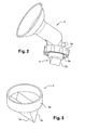
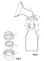
- the support means of the non-return valve is thus made from an assembly and comprises two constituents (10) and (11) which are capable of being assembled together in a fixed or removable manner and enclosing a nonreturn valve (12), the first component (10) being capable of being positioned on the inner sleeve (2c) of the base (2a) of the while the other component (11) provides a double function, on the one hand protecting the non-return valve (12) and on the other hand being the exclusive means of grip and manipulation by the user when maintenance and cleaning operations of said non-return valve, said component (11) opening into the bottle.
- the first component (10) comprises a central base (10a) of circular configuration which is extended on one side by a cylindrical bearing surface (10b), which is capable of coming to bear on the sleeve (2c) mentioned above, and of other by a cylindrical bearing (10c) of larger diameter.
- the latter has at the end on its front face (10d) a protruding extension (10e) established over the entire disc surface of said front face.
- the base (10a) also defines a horizontal support plane (10f) which is likely to be in contact with the non-return valve (12).
- the second component (11) comprises a circular central base (11a) extending on one side by a cylindrical surface (11b) able to surround the cylindrical surface (10c) of the component (10) and on the other side by a cylindrical bearing (11c) of greater length forming a protective sleeve.
- the central base (11a) is internally extended with a protruding shape (11d) projecting upwards and capable of being in contact with the non-return valve (12) by its ring (12a).
- the central base (11a) comprises a horizontal bearing plane (11e) against which the disc front face (10d) bears against the formation of a circular groove (11f) capable of receiving the projecting form (10e) above formed on the constituent (10).
- the component (10) is centered within the component (11).
- the non-return valve (12), as shown figure 8 comprises a cylindrical crown (12a) upper which is extended by two lips (12b) oriented inclined relative to each other from said crown and meeting at the end projecting. These lips leave an opening (12c) at the end for the passage of the collected milk.
- the cylindrical ring (12a) is thus positioned in the interior space formed between the constituents (10) and (11) as shown figure 6 , and more specifically in the volume defined between their bases (10a) and (11a).
- the projecting shape (11c) established on the base (11a) of the second component comes into contact and bears against the crown portion of the non-return valve.
- Said valve being made of an elastomeric material, it is deformed substantially at the point of penetration of the aforementioned projecting shape (11c) thus ensuring a locking in position.
- connection between the constituents (11) and (12) can be fixed or removable. There may be a tight fit after installation of the check valve. There may be a connection by clipping engagement configurations using complementary male-female forms formed on the facing portions of said components.
- the height of the cylindrical seat (11c) is greater than the height of the lips (12b) of the non-return valve so as to protect them.
- the device forms a single assembly constituting a kind of tip which is then positioned on the sleeve (2c) receiver provided inside the base of the nipple shield.
- This The assembly can be easily disassembled and subsequently manipulated for the purpose of cleaning the non-return valve. It is not necessary to disassemble the latter with respect to the components (10) and (11) of the device. Handling of the device is done from the outside without contact with the non-return valve and thus under optimized hygiene conditions. The non-return valve is not handled per se and is therefore not deformed with use.
- the height of the cylindrical bearing surface (11c) of the component (11) is large enough to prevent penetration of the user's fingers with contact on the non-return valve.
- Complementary sealing elements may be provided in the positioning and connection of the device on the sleeve in the base of the nipple. These are, for example, O-rings or the like.
- the constituents (10) and (11) may comprise lights, of lower section than the passage of a finger.
- the non-return valve is made of an elastomeric material and can be sterilized and, if necessary, both components (10) and (11).
- the constituents (10) and (11) may be made of any material, for example plastic by being rigid, and may have a visual effect of transparency or opaque. It can also be envisaged without departing from the scope of the invention that the constituents (10) and (11) can constitute in themselves a single piece by overmolding while allowing the introduction and clipping in position of the non-return valve .
- FIG 11 another embodiment of the invention that the nipple is directly arranged during its manufacture with on the one hand the sleeve portion (2c) for receiving the non-return valve but also with the means (4) which protects the said non-return valve by being of sufficient height to protrude from the end of the said flapper.
- FIG 12 an alternative embodiment of the non-return valve.
- the latter is capable of receiving, at the bottom end, directly or in an attached manner, a perforated means (13) in the form of a grid, for example, so as to prevent the penetration of a finger.
- This means is attached, clipped or otherwise on said end of the check valve, while allowing the flow of milk through the openings (13a).
- the height of the support means (4) or the constituent (11) is such that it allows the limited accessibility of the user to the end portion of the lips of the non-return valve for purposes of seizure .
Landscapes
- Health & Medical Sciences (AREA)
- Heart & Thoracic Surgery (AREA)
- Vascular Medicine (AREA)
- Engineering & Computer Science (AREA)
- Anesthesiology (AREA)
- Biomedical Technology (AREA)
- Hematology (AREA)
- Life Sciences & Earth Sciences (AREA)
- Animal Behavior & Ethology (AREA)
- General Health & Medical Sciences (AREA)
- Public Health (AREA)
- Veterinary Medicine (AREA)
- Pediatric Medicine (AREA)
- External Artificial Organs (AREA)
Applications Claiming Priority (1)
| Application Number | Priority Date | Filing Date | Title |
|---|---|---|---|
| FR1162510A FR2985188B1 (fr) | 2011-12-29 | 2011-12-29 | Dispositif anti retour de fluides incorpore dans un ensemble d'expression de lait maternel |
Publications (1)
| Publication Number | Publication Date |
|---|---|
| EP2609942A1 true EP2609942A1 (de) | 2013-07-03 |
Family
ID=47324008
Family Applications (1)
| Application Number | Title | Priority Date | Filing Date |
|---|---|---|---|
| EP12306517.9A Withdrawn EP2609942A1 (de) | 2011-12-29 | 2012-12-05 | Flüssigkeits-Rücklaufsperren-Vorrichtung, die in eine Muttermilchexpressionseinheit eingebaut ist |
Country Status (2)
| Country | Link |
|---|---|
| EP (1) | EP2609942A1 (de) |
| FR (1) | FR2985188B1 (de) |
Cited By (2)
| Publication number | Priority date | Publication date | Assignee | Title |
|---|---|---|---|---|
| WO2016128832A1 (en) * | 2015-02-10 | 2016-08-18 | Medela Holding Ag | Media separation device |
| CN110448744A (zh) * | 2018-05-21 | 2019-11-15 | 湖北文理学院 | 一种吸奶器鸭嘴阀的辅助固定装置 |
Families Citing this family (1)
| Publication number | Priority date | Publication date | Assignee | Title |
|---|---|---|---|---|
| FR3027807A1 (fr) | 2014-11-05 | 2016-05-06 | La Diffusion Technique Francaise | Ensemble d'expression de lait maternel |
Citations (2)
| Publication number | Priority date | Publication date | Assignee | Title |
|---|---|---|---|---|
| US20050154349A1 (en) | 2003-08-08 | 2005-07-14 | Playtex Products, Inc. | Manual breast pump |
| US20070179439A1 (en) | 2005-04-07 | 2007-08-02 | Stefan Vogelin | Valve, in particular for a breast shield set |
-
2011
- 2011-12-29 FR FR1162510A patent/FR2985188B1/fr not_active Expired - Fee Related
-
2012
- 2012-12-05 EP EP12306517.9A patent/EP2609942A1/de not_active Withdrawn
Patent Citations (2)
| Publication number | Priority date | Publication date | Assignee | Title |
|---|---|---|---|---|
| US20050154349A1 (en) | 2003-08-08 | 2005-07-14 | Playtex Products, Inc. | Manual breast pump |
| US20070179439A1 (en) | 2005-04-07 | 2007-08-02 | Stefan Vogelin | Valve, in particular for a breast shield set |
Cited By (4)
| Publication number | Priority date | Publication date | Assignee | Title |
|---|---|---|---|---|
| WO2016128832A1 (en) * | 2015-02-10 | 2016-08-18 | Medela Holding Ag | Media separation device |
| CN107427615A (zh) * | 2015-02-10 | 2017-12-01 | 梅德拉控股公司 | 介质分离装置 |
| US10773001B2 (en) | 2015-02-10 | 2020-09-15 | Medela Holding Ag | Media separation device |
| CN110448744A (zh) * | 2018-05-21 | 2019-11-15 | 湖北文理学院 | 一种吸奶器鸭嘴阀的辅助固定装置 |
Also Published As
| Publication number | Publication date |
|---|---|
| FR2985188B1 (fr) | 2015-02-13 |
| FR2985188A1 (fr) | 2013-07-05 |
Similar Documents
| Publication | Publication Date | Title |
|---|---|---|
| EP2805649B1 (de) | Kochtopf, der ein dichtes Steuermodul umfasst | |
| EP2805650B1 (de) | Kochtopf, der ein dichtes Gehäuse umfasst | |
| FR2987607A1 (fr) | Bouchon pour un col de recipient | |
| CA3154857A1 (fr) | Dispositif d'echappement anti propagation de batteries lithium-ion d'aeronef | |
| EP2609942A1 (de) | Flüssigkeits-Rücklaufsperren-Vorrichtung, die in eine Muttermilchexpressionseinheit eingebaut ist | |
| EP2162663A2 (de) | Steckverbinder mit verbesserter aussenreinigung | |
| WO2011007099A1 (fr) | Dispositif interface perfectionne d'injection | |
| FR2859971A1 (fr) | Obturateur pour partie creuse de vehicule automobile | |
| FR2594206A1 (fr) | Dispositif d'amortissement phonique pour conduite d'installation sanitaire | |
| CA2490311A1 (fr) | Siphon pour evier ou similaire | |
| EP1444051B1 (de) | Fluidabgabevorrichtung | |
| FR2605293A1 (fr) | Bouchon equipe d'une valve de degazage | |
| FR2933938A1 (fr) | Insert de bouchon de reservoir de liquide de frein | |
| EP2010726B1 (de) | Siphonvorrichtung für eine sanitärvorrichtung | |
| BE1009922A7 (fr) | Bouchon de fermeture d'un orifice realise dans une enveloppe de protection. | |
| EP2746471B1 (de) | Wasserentfernungsvorrichtung | |
| EP2110308B1 (de) | Lagerbehälter für Ausrüstungsgegenstände, insbesondere eines Rettungsfloßes anhand von Unterdruck gesclossen | |
| EP0814004A1 (de) | Dichtungsring für die Antriebswelle eines Scheibenwischers | |
| EP2935909B1 (de) | Dichtungsventil für ein befestigungssystem | |
| FR2816025A1 (fr) | Clapet d'entree d'air | |
| EP1690476A1 (de) | Mittel zum Halten eines Geräts wie einen Löffel in einer Behälteröffnung | |
| FR2921827A1 (fr) | Dispositif pour la protection de la tetine d'un biberon | |
| EP3823114A1 (de) | Dichtung und elektrisches gehäuse mit einer solchen dichtung | |
| FR2805028A1 (fr) | Luminaire comportant deux parties assemblees de facon etanche | |
| FR2873611A1 (fr) | Dispositif pour assurer l'etancheite de gants dans des installations pharmaceutiques |
Legal Events
| Date | Code | Title | Description |
|---|---|---|---|
| PUAI | Public reference made under article 153(3) epc to a published international application that has entered the european phase |
Free format text: ORIGINAL CODE: 0009012 |
|
| AK | Designated contracting states |
Kind code of ref document: A1 Designated state(s): AL AT BE BG CH CY CZ DE DK EE ES FI FR GB GR HR HU IE IS IT LI LT LU LV MC MK MT NL NO PL PT RO RS SE SI SK SM TR |
|
| AX | Request for extension of the european patent |
Extension state: BA ME |
|
| 17P | Request for examination filed |
Effective date: 20131227 |
|
| RBV | Designated contracting states (corrected) |
Designated state(s): AL AT BE BG CH CY CZ DE DK EE ES FI FR GB GR HR HU IE IS IT LI LT LU LV MC MK MT NL NO PL PT RO RS SE SI SK SM TR |
|
| STAA | Information on the status of an ep patent application or granted ep patent |
Free format text: STATUS: THE APPLICATION IS DEEMED TO BE WITHDRAWN |
|
| 18D | Application deemed to be withdrawn |
Effective date: 20160701 |