EP2610000A1 - Structure à trois portes adaptée à un malaxeur de solution de couchage du type à rotation autour de deux axes - Google Patents
Structure à trois portes adaptée à un malaxeur de solution de couchage du type à rotation autour de deux axes Download PDFInfo
- Publication number
- EP2610000A1 EP2610000A1 EP11847905.4A EP11847905A EP2610000A1 EP 2610000 A1 EP2610000 A1 EP 2610000A1 EP 11847905 A EP11847905 A EP 11847905A EP 2610000 A1 EP2610000 A1 EP 2610000A1
- Authority
- EP
- European Patent Office
- Prior art keywords
- door
- right front
- paint mixer
- moving bracket
- cabinet
- Prior art date
- Legal status (The legal status is an assumption and is not a legal conclusion. Google has not performed a legal analysis and makes no representation as to the accuracy of the status listed.)
- Granted
Links
Images






Classifications
-
- E—FIXED CONSTRUCTIONS
- E06—DOORS, WINDOWS, SHUTTERS, OR ROLLER BLINDS IN GENERAL; LADDERS
- E06B—FIXED OR MOVABLE CLOSURES FOR OPENINGS IN BUILDINGS, VEHICLES, FENCES OR LIKE ENCLOSURES IN GENERAL, e.g. DOORS, WINDOWS, BLINDS, GATES
- E06B3/00—Window sashes, door leaves, or like elements for closing wall or like openings; Layout of fixed or moving closures, e.g. windows in wall or like openings; Features of rigidly-mounted outer frames relating to the mounting of wing frames
- E06B3/32—Arrangements of wings characterised by the manner of movement; Arrangements of movable wings in openings; Features of wings or frames relating solely to the manner of movement of the wing
- E06B3/50—Arrangements of wings characterised by the manner of movement; Arrangements of movable wings in openings; Features of wings or frames relating solely to the manner of movement of the wing with more than one kind of movement
- E06B3/5054—Arrangements of wings characterised by the manner of movement; Arrangements of movable wings in openings; Features of wings or frames relating solely to the manner of movement of the wing with more than one kind of movement where the sliding and rotating movements are independent of each other
- E06B3/5081—Arrangements of wings characterised by the manner of movement; Arrangements of movable wings in openings; Features of wings or frames relating solely to the manner of movement of the wing with more than one kind of movement where the sliding and rotating movements are independent of each other at least two wings have a different kind of movement
-
- F—MECHANICAL ENGINEERING; LIGHTING; HEATING; WEAPONS; BLASTING
- F16—ENGINEERING ELEMENTS AND UNITS; GENERAL MEASURES FOR PRODUCING AND MAINTAINING EFFECTIVE FUNCTIONING OF MACHINES OR INSTALLATIONS; THERMAL INSULATION IN GENERAL
- F16P—SAFETY DEVICES IN GENERAL; SAFETY DEVICES FOR PRESSES
- F16P3/00—Safety devices acting in conjunction with the control or operation of a machine; Control arrangements requiring the simultaneous use of two or more parts of the body
- F16P3/08—Safety devices acting in conjunction with the control or operation of a machine; Control arrangements requiring the simultaneous use of two or more parts of the body in connection with the locking of doors, covers, guards, or like members giving access to moving machine parts
-
- B—PERFORMING OPERATIONS; TRANSPORTING
- B01—PHYSICAL OR CHEMICAL PROCESSES OR APPARATUS IN GENERAL
- B01F—MIXING, e.g. DISSOLVING, EMULSIFYING OR DISPERSING
- B01F35/00—Accessories for mixers; Auxiliary operations or auxiliary devices; Parts or details of general application
- B01F35/40—Mounting or supporting mixing devices or receptacles; Clamping or holding arrangements therefor
- B01F35/42—Clamping or holding arrangements for mounting receptacles on mixing devices
- B01F35/423—Clamping or holding arrangements for mounting receptacles on mixing devices of the vertically movable, two-plates type
-
- B—PERFORMING OPERATIONS; TRANSPORTING
- B01—PHYSICAL OR CHEMICAL PROCESSES OR APPARATUS IN GENERAL
- B01F—MIXING, e.g. DISSOLVING, EMULSIFYING OR DISPERSING
- B01F35/00—Accessories for mixers; Auxiliary operations or auxiliary devices; Parts or details of general application
- B01F35/45—Closures or doors specially adapted for mixing receptacles; Operating mechanisms therefor
-
- F—MECHANICAL ENGINEERING; LIGHTING; HEATING; WEAPONS; BLASTING
- F16—ENGINEERING ELEMENTS AND UNITS; GENERAL MEASURES FOR PRODUCING AND MAINTAINING EFFECTIVE FUNCTIONING OF MACHINES OR INSTALLATIONS; THERMAL INSULATION IN GENERAL
- F16P—SAFETY DEVICES IN GENERAL; SAFETY DEVICES FOR PRESSES
- F16P1/00—Safety devices independent of the control and operation of any machine
Definitions
- the present application relates to a double gyroscopic mixer for coating, paint and the like and, particularly to, a tri-directional-sliding door structure for a double gyroscopic paint mixer.
- mixers in coating industry include vibrating mixers and rotating mixers (i.e., gyroscopic mixers).
- the present application relates to a gyroscopic mixer, and particularly to an automatic double gyroscopic mixer.
- a double gyroscopic mixer is an apparatus for blending or mixing coatings, paints and the like, which can allow a barrel containing coatings, paints and the like (hereinafter, being referred to therein as coating barrel for short) to rotate about a rotation axis perpendicular to a geometric center line of the coating barrel while rotating about the geometric center line of the coating barrel in the double gyroscopic mixer, i.e. performing a rotation and a revolution at the same time, so as to mix coatings by a double rotating.
- the coating barrel is put into a double gyroscopic mixer between an upper clamping plate 4' and the lower clamping plate 6' and on the lower clamping plate, wherein the upper clamping plate 4' and the lower clamping plate 6' are located between an upper supporting arm 3' and a lower supporting arm 5' (referring to Figures 1 , 2 and 3 which show automatic double gyroscopic mixers available in the present market).
- a number of such automatic double gyroscopic mixers each include a lower supporting arm consisting of two parts, one of which can be pulled out outwardly so as to pull the lower clamping plate out and then can be pushed inwardly after the coating barrel has been placed, thus reducing the difficulty in placing the coating barrel into the mixer.
- a door structure of such a double gyroscopic mixer available in present market mainly is a structure shown in Figures 1 and 2 .
- a door 2' is of a plate-like structure, with one end being fixed on a rotating shaft, and the entire door structure can rotate about this rotating shaft to close or open the door.
- This door structure is in the most common form, but may arise a main problem that, after the door is opened, only a front space of the machine is opened, resulting in a relatively small opened space of the machine.
- the upper clamping plate and the lower clamping plate of the mixing structure of the double gyroscopic mixer and the coating barrel pressed are located within a cabinet shell 1' of the entire machine, when it is required to take the coating barrel out, an operator has to do this through the space opened by the door structure.
- the coating barrel is usually heavy, and thus it is difficultly taken out somewhat.
- FIG 3 shows another door structure of a gyroscopic mixer available in the present market.
- the entire door structure covers a front side and a top side of the machine cabinet shell 1', and a door hinge of the door is generally arranged at the rear of the top side of the machine, so that the entire door 2' is similar to "L" in structure and appearance. Since the space opened by this door structure is relatively large, that is, the front side and the top side of the cabinet shell can be opened, it is more convenient for users to put in or take out a color paint barrel. Also, for this door structure, when the door is opened, there is a need for more space above the machine.
- a gyroscopic mixer having a rolling door structure is available in the present market.
- the gyroscopic mixer having such a door structure more space of the machine can be opened, and there is no requirement on the external space of the machine. Therefore, the gyroscopic mixer with the door structure is widely favorable in the market.
- such a door structure has problems in insufficient strength of the door and relatively large noise generated from a door curtain in the operation of the machine. Moreover, it is difficult to solve a problem that such a door structure cannot be pulled or pushed smoothly in use.
- an object of the present application is to specially design a tri-directional-sliding door structure suitable for a gyroscopic paint mixer.
- a top cover, a left front door and a right front door of a machine designed according to the present application are connected through linear guiding rails and hinged mounting structures, and thus the interaction between the top cover and the left and right front doors of the machine can be carried out only by pushing the top cover on the machine shell, so as to open and close a top side and a front side of the machine shell; and opening and closing of the three directional doors, i.e. the top cover, and the left and right front doors, only take the inner space of the machine shell, thereby greatly lowering the requirement on external space of the machine and being convenient in use.
- a tri-directional-sliding door structure suitable for a double gyroscopic paint mixer which includes a top cover, left and right front doors symmetrically arranged, a door-moving bracket, and left and right linear guiding rails, wherein the top cover is located at the top of a cabinet and is fixedly mounted on the door-moving bracket, the left and right front doors are symmetrically arranged on a front side of the cabinet, the left and right linear guiding rails are mounted on a cabinet shell by guiding rail fixing holders respectively, left and right sides of the door-moving bracket are symmetrically connected to sliders arranged on and sliding along the linear guiding rails, the left and right front doors are symmetrically hinged to two sides of the door-moving bracket, and lower ends of the left and right front doors are both interacted with a fixing holder at the bottom of the cabinet via connecting parts.
- the lower ends of the front doors may be connected to the fixing holder at the bottom of the cabinet in two manners as follows: i) the lower ends of the left and right front doors are both hinged to the fixing holder at the bottom of the cabinet via connecting rods; ii) the lower ends of the left and right front doors are both interacted with an arc guiding groove arranged in the fixing holder via rotating wheels.
- a paint mixer including a cabinet shell; a left guiding rail fixedly arranged on a left side of the cabinet shell and a right guiding rail fixedly arranged on a right side of the cabinet shell; a left slider and a right slider capable of sliding on the left guiding rail and the right guiding rail respectively; a door-moving bracket connected with the left slider and the right slider; a top cover which is located at the top of the cabinet shell and fixedly mounted on the door-moving bracket; and a left front door and a right front door which are symmetrically arranged on a front side of the cabinet shell and are respectively hinged to a left end and a right end of the door-moving bracket, wherein lower ends of the left front door and the right front door are connected to a fixing holder at the bottom of the cabinet shell.
- the left guiding rail and the right guiding rail are linear guiding rails, respectively.
- the left guiding rail and the right guiding rail are fixedly mounted on the cabinet shell by guiding rail fixing holders, respectively.
- a left end of the left front door and a right end of the right front door are hinged to the door-moving bracket via rotating shafts, respectively.
- the lower end of the left front door and the lower end of the right front door are hinged to the fixing holder at the bottom of the cabinet shell via connecting rods, respectively.
- the lower end of the left front door and the lower end of the right front door are interacted with a guiding groove arranged in the fixing holder via rotating wheels, respectively.
- the paint mixer is one of a gyroscopic paint mixer, a double gyroscopic paint mixer and a vibrating mixer.
- the top cover on the cabinet has a left end connected to the left slider and a right end connected to the right slider.
- the left and right linear guiding rails are symmetrically fixed on the cabinet shell.
- the left and right sliders are symmetrically fixed on the door-moving bracket.
- the left end of the left front door is coupled to the left end of the door-moving bracket via a door rotating shaft in hinged way;
- the right end of the right front door is coupled to the right end of the door-moving bracket via another door rotating shaft in hinged way;
- the lower end of the left front door and the lower end of the right front door are coupled symmetrically via connecting rods and the rotating shaft to the fixing holder fixed at the bottom of the cabinet in hinged way, respectively.
- the top cover of the cabinet When it is required to open the thi-directional doors of the cabinet, the top cover of the cabinet is pushed, and the door-moving bracket coupled with the top cover drives the left and right sliders to slide inwardly on the left and right linear guiding rails respectively.
- the left front end of the door-moving bracket hingedly drives the left front door to move inwardly
- the right front end of the door-moving bracket hingedly drives the right front door to move inwardly.
- the lower end of the left front door is rotated about a hinged bearing by the left door connecting rod
- the lower end of the right front door is rotated about another hinged bearing by the right door connecting rod.
- the left and right front doors perform a longitudinal movement and a rotation movement by means of the door-moving bracket and the hinged structure.
- the top cover of the cabinet When it is required to close the thi-directional doors of the cabinet, the top cover of the cabinet is pulled, and the door-moving bracket coupled with the top cover drives the left and right sliders to slide outwardly on the left and right linear guiding rails respectively.
- the left front end of the door-moving bracket hingedly drives the left front door to move outwardly
- the right front end of the door-moving bracket hingedly drives the right front door to move outwardly.
- the lower end of the left front door is rotated about the hinged bearing by the left door connecting rod
- the lower end of the right front door is rotated about the hinged bearing by the right door connecting rod.
- the left and right front doors perform the longitudinal movement and the rotation movement by means of the door-moving bracket and the hinged structure.
- the present application has a major advantage in that, by pushing and pulling the top cover, the left and right front doors may be opened and closed by means of the hinged structure associated with the door-moving bracket, the left and right front doors, the bearing fixing holder and the connecting rods.
- the transmission and direction changing may be achieved by taking full advantage of hinged joint, so as to implement the tri-directional interaction between the top cover and the left and right front doors, resulting in a simple and convenient operation, sufficient utilization of the inner space of the cabinet, and a safe and reliable structure.
- Figure 1 is a structural schematic view of a double gyroscopic mixer of the prior art
- Figure 2 is a schematic view of a rotation door structure of the prior art
- Figure 3 is a schematic view of an L-shaped door structure of the prior art
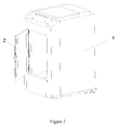
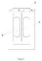
- Figure 4 is a front view of an entire structure of a tri-directional-sliding door double gyroscopic mixer of the present application (with doors being closed);
- Figure 5 is a front view of the entire structure of the tri-directional-sliding door double gyroscopic mixer of the present application (with doors being opened);
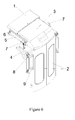
- Figure 6 is an isometric view of an assembly of a tri-directional-sliding door structure of the present application (with doors being closed);
- Figure 7 is an isometric view of the assembly of the tri-directional-sliding door structure of the present application (with doors being opened);
- Figure 8 is a top view of the assembly of the tri-directional-sliding door structure of the present application.
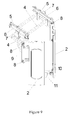
- Figure 9 is an isometric view showing the hinged connection of the tri-directional-sliding door structure of the present application.
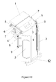
- Figure 10 is an isometric view showing the guiding-groove coupling structure of a left front door and a right front door of the present application (with doors being opened);
- Figure 11 is an isometric view showing the guiding-groove coupling structure of the left front door and the right front door of the present application (with doors being closed).
- Reference numerals in Figures 4 to 11 1 shell, 2 front door, 3 top cover, 4 door-moving bracket, 5 guiding rail fixing holder, 6 guiding rail, 7 slider, 8 rotating shaft, 9 doorframe, 10 door connecting rod, 11 fixing holder, 12 guiding groove.
- a tri-directional-sliding door structure suitable for a double gyroscopic paint mixer of the present application includes a top cover 3, left and right front doors 2 arranged symmetrically, a door-moving bracket 4, and left and right linear guiding rails 6.
- the top cover 3 is located at the top of a cabinet and is fixedly mounted on the door-moving bracket 4.
- the left and right front doors 2 are symmetrically arranged on a front side of the cabinet.
- the left and right linear guiding rails 6 are mounted on a cabinet shell 1 via guiding rail fixing holders 5, respectively.
- the left and right sides of the door-moving bracket 4 is symmetrically connected to sliders 7 arranged on and sliding along the left and right linear guiding rails 6 respectively.
- the left and right front doors are symmetrically hinged to two sides of the door-moving bracket 4 via doorframes 9, and the lower ends of the left and right front doors 2 are both interacted with a fixing holder 11 at the bottom of the cabinet through connecting parts.
- the lower ends of the front doors 2 may be connected to the fixing holder 11 at the bottom of the cabinet in two manners as follows: i) the lower ends of the left and right front doors 2 are both hinged to the fixing holder 11 at the bottom of the cabinet via door connecting rods 10 (referring to Figure 7 ); ii) the lower ends of the left and right front doors 2 are both interacted with an arc guiding groove 12 arranged in the fixing holder 11 via rotating wheels (referring to Figure 10 ).
- the top cover 3 on the cabinet has a left end connected to the left slider 7 and a right end connected to the right slider 7.
- the left and right linear guiding rails 6 are symmetrically fixed on the cabinet shell 1.
- the left and right sliders 7 are symmetrically fixed on the door-moving bracket 4.
- the left end of the left front door 2 is coupled to the left end of the door-moving bracket 4 via a door rotating shaft 8 in hinged way;
- the right end of the right front door 2 is coupled to the right end of the door-moving bracket 4 via another door rotating shaft 8 in hinged way;
- the lower end of the left front door 2 and the lower end of the right front door 2 are coupled symmetrically via connecting rods 10 and the rotating shaft to the fixing holder 11 fixed at the bottom of the cabinet in hinged way, respectively.
- the top cover 3 of the cabinet When it is required to open the thi-directional doors of the cabinet, the top cover 3 of the cabinet is pushed, and the door-moving bracket 4 coupled with the top cover 3 drives the left and right sliders 7 to slide inwardly on the left and right linear guiding rails 6 respectively.
- the right front end of the door-moving bracket 4 hingedly drives the right front door 2 to move inwardly.
- the lower end of the left front door 2 is rotated about a hinged bearing by the left door connecting rod 10
- the lower end of the right front door 2 is rotated about another hinged bearing by the right door connecting rod 10.
- the left and right front doors 2 perform a longitudinal movement and a rotation movement by means of the door-moving bracket 4 and the hinged structure.
- the top cover 3 of the cabinet When it is required to close the thi-directional doors of the cabinet, the top cover 3 of the cabinet is pulled, and the door-moving bracket 4 coupled with the top cover 3 drives the left and right sliders 7 to slide outwardly on the left and right linear guiding rails 6 respectively.
- the right front end of the door-moving bracket 4 hingedly drives the right front door 2 to move outwardly.
- the lower end of the left front door 2 is rotated about the hinged bearing by the left door connecting rod 10
- the lower end of the right front door 2 is rotated about the hinged bearing by the right door connecting rod 10.
- the left and right front doors 2 perform the longitudinal movement and the rotation movement by means of the door-moving bracket 4 and the hinged structure.
- the present application has a major advantage in that, by pushing and pulling the top cover 3, the left and right front doors 2 may be opened and closed by means of the hinged structure associated with the door-moving bracket 4, the left and right front doors 2, the bearing fixing holder 11 and the connecting rods 10.
- the transmission and direction changing may be achieved by taking full advantage of hinged joint, so as to implement the tri-directional interaction between the top cover 3 and the left and right front doors 2, resulting in a simple and convenient operation, sufficient utilization of the inner space of the cabinet, and a safe and reliable structure.
- the present application is described by examples of a tri-directional-sliding door structure suitable for a double gyroscopic paint mixer, but is not limited thereto.
- the present application is also applicable to vibrating mixers, other types of gyroscopic paint mixers and other types of paint mixers.
Landscapes
- Engineering & Computer Science (AREA)
- General Engineering & Computer Science (AREA)
- Mechanical Engineering (AREA)
- Chemical & Material Sciences (AREA)
- Chemical Kinetics & Catalysis (AREA)
- Civil Engineering (AREA)
- Structural Engineering (AREA)
- Paints Or Removers (AREA)
- Freezers Or Refrigerated Showcases (AREA)
- Processing And Handling Of Plastics And Other Materials For Molding In General (AREA)
- Hinges (AREA)
- Accessories For Mixers (AREA)
Applications Claiming Priority (2)
| Application Number | Priority Date | Filing Date | Title |
|---|---|---|---|
| CN2010206558771U CN201978695U (zh) | 2010-12-13 | 2010-12-13 | 适用于双回转式涂料混匀机的三向门结构 |
| PCT/CN2011/083833 WO2012079494A1 (fr) | 2010-12-13 | 2011-12-12 | Structure à trois portes adaptée à un malaxeur de solution de couchage du type à rotation autour de deux axes |
Publications (4)
| Publication Number | Publication Date |
|---|---|
| EP2610000A1 true EP2610000A1 (fr) | 2013-07-03 |
| EP2610000A4 EP2610000A4 (fr) | 2014-03-12 |
| EP2610000B1 EP2610000B1 (fr) | 2015-04-29 |
| EP2610000B8 EP2610000B8 (fr) | 2015-06-03 |
Family
ID=44606164
Family Applications (1)
| Application Number | Title | Priority Date | Filing Date |
|---|---|---|---|
| EP11847905.4A Active EP2610000B8 (fr) | 2010-12-13 | 2011-12-12 | Structure à trois portes adaptée à un malaxeur de solution de couchage du type à rotation autour de deux axes |
Country Status (6)
| Country | Link |
|---|---|
| US (1) | US9422764B2 (fr) |
| EP (1) | EP2610000B8 (fr) |
| CN (1) | CN201978695U (fr) |
| BR (1) | BR112013009812A2 (fr) |
| IN (1) | IN2013DN02543A (fr) |
| WO (1) | WO2012079494A1 (fr) |
Cited By (1)
| Publication number | Priority date | Publication date | Assignee | Title |
|---|---|---|---|---|
| CN116899515A (zh) * | 2023-09-12 | 2023-10-20 | 山东龙口三元铝材有限公司 | 涂料恒温分散式反应装置 |
Families Citing this family (8)
| Publication number | Priority date | Publication date | Assignee | Title |
|---|---|---|---|---|
| DE102010026478A1 (de) * | 2010-07-07 | 2012-01-12 | Tammo Bialas | System zum Anzeigen eines ärztlichen Diagnoseergebnisses |
| CN201978695U (zh) * | 2010-12-13 | 2011-09-21 | 沈如华 | 适用于双回转式涂料混匀机的三向门结构 |
| US9332842B2 (en) * | 2012-03-28 | 2016-05-10 | BIOMéRIEUX, INC. | Sliding hinges and related methods and devices suitable for apparatus for automated evaluation of microorganism growth in test samples |
| CN107701003A (zh) * | 2017-10-12 | 2018-02-16 | 中国航发南方工业有限公司 | 用于零件清洗舱的舱门及零件清洗舱 |
| USD919110S1 (en) * | 2019-08-09 | 2021-05-11 | Precision Nanosystems Inc. | Laboratory mixer |
| CN111603982A (zh) * | 2020-05-22 | 2020-09-01 | 王梦莲 | 一种医疗护理用药液摇匀装置 |
| CN112854963A (zh) * | 2021-01-06 | 2021-05-28 | 中国原子能科学研究院 | 一种联动开关门机构 |
| EP4160076B1 (fr) * | 2021-10-01 | 2024-03-13 | Nordischer Maschinenbau Rud. Baader Gmbh + Co Kg | Dispositif de traitement de produits |
Family Cites Families (12)
| Publication number | Priority date | Publication date | Assignee | Title |
|---|---|---|---|---|
| US4037827A (en) | 1975-12-15 | 1977-07-26 | F.P.E.C. Corporation | Food product mixer with an improved door mechanism |
| JPH05146319A (ja) | 1991-11-27 | 1993-06-15 | Sanyo Electric Co Ltd | 扉装置 |
| DE19611546C1 (de) * | 1996-03-23 | 1997-08-07 | Collomix Ruehr Mischgeraete | Biaxialmischer |
| US5711601A (en) * | 1996-06-21 | 1998-01-27 | Fluid Management, Inc. | Mixing apparatus for pulverulent materials |
| DE10020804A1 (de) * | 2000-04-28 | 2001-11-08 | Deckel Maho Geretsried Gmbh | Schutzabdeckung für eine Werkzeugmaschine |
| DE10023073B4 (de) | 2000-05-11 | 2008-06-19 | Volkswagen Ag | Schutzelement-Antrieb-System |
| US6850020B1 (en) * | 2003-09-26 | 2005-02-01 | Red Devil Equipment Company | Multizone clamping system for paint mixer |
| US7059763B2 (en) | 2003-10-22 | 2006-06-13 | Fast & Fluid Management, S.R.I. | Gyroscopic mixer |
| CN201119399Y (zh) | 2007-11-25 | 2008-09-24 | 江苏牧羊集团有限公司 | 一种混合机出料门控制机构 |
| US8157436B2 (en) * | 2008-02-15 | 2012-04-17 | Red Devil Equipment Company | Multi-size mixer |
| CN201978695U (zh) | 2010-12-13 | 2011-09-21 | 沈如华 | 适用于双回转式涂料混匀机的三向门结构 |
| CN201912909U (zh) | 2010-12-14 | 2011-08-03 | 沈如华 | 适用于振动式混匀机的三向门结构 |
-
2010
- 2010-12-13 CN CN2010206558771U patent/CN201978695U/zh not_active Expired - Lifetime
-
2011
- 2011-12-12 WO PCT/CN2011/083833 patent/WO2012079494A1/fr not_active Ceased
- 2011-12-12 IN IN2543DEN2013 patent/IN2013DN02543A/en unknown
- 2011-12-12 US US13/878,348 patent/US9422764B2/en active Active
- 2011-12-12 EP EP11847905.4A patent/EP2610000B8/fr active Active
- 2011-12-12 BR BR112013009812A patent/BR112013009812A2/pt not_active IP Right Cessation
Cited By (2)
| Publication number | Priority date | Publication date | Assignee | Title |
|---|---|---|---|---|
| CN116899515A (zh) * | 2023-09-12 | 2023-10-20 | 山东龙口三元铝材有限公司 | 涂料恒温分散式反应装置 |
| CN116899515B (zh) * | 2023-09-12 | 2023-11-14 | 山东龙口三元铝材有限公司 | 涂料恒温分散式反应装置 |
Also Published As
| Publication number | Publication date |
|---|---|
| WO2012079494A1 (fr) | 2012-06-21 |
| EP2610000B1 (fr) | 2015-04-29 |
| US9422764B2 (en) | 2016-08-23 |
| EP2610000A4 (fr) | 2014-03-12 |
| IN2013DN02543A (fr) | 2015-08-07 |
| EP2610000B8 (fr) | 2015-06-03 |
| BR112013009812A2 (pt) | 2016-07-26 |
| CN201978695U (zh) | 2011-09-21 |
| US20130265844A1 (en) | 2013-10-10 |
Similar Documents
| Publication | Publication Date | Title |
|---|---|---|
| US9422764B2 (en) | Three-door structure suitable for two-axis rotation type coating mixer | |
| CN207905577U (zh) | 一种烤箱开门结构 | |
| KR20130046611A (ko) | 전동식 폴딩 도어 시스템 | |
| CN108691471B (zh) | 用于多部件门的滑动和枢转组合式运动的家具配件和具有该家具配件的家具 | |
| CN103743078A (zh) | 空调器及其双开关门结构 | |
| CN110094131B (zh) | 一种烤箱开门结构 | |
| CN109209075A (zh) | 自动锁闭装置及门窗 | |
| CN107605306A (zh) | 一种新型无动力旋转对开门 | |
| CN110094133A (zh) | 一种烤箱开门结构 | |
| CN101728775B (zh) | 具有提升锁定功能的开关柜防爆门 | |
| CN220036439U (zh) | 一种双向自动折叠门的电控系统 | |
| CN110512996A (zh) | 一种室内智能平开门 | |
| CN110736137B (zh) | 空调器 | |
| DE202014005067U1 (de) | Vorrichtung zum Öffnen und zum Schließen eines schwenkbaren Teils eines Möbels mittels Funksteuerung sowie Möbel | |
| CN203810673U (zh) | 空调器及其双开关门结构 | |
| CN219864699U (zh) | 折叠门 | |
| CN112554699A (zh) | 一种加工设备箱门开启机构 | |
| CN109403797B (zh) | 一种单扇可左右开启的门窗 | |
| CN216534863U (zh) | 一种用于罗马杆窗帘自动开合器的调节装置 | |
| CN216240234U (zh) | 一种共面门的同步机构及柜体结构 | |
| CN215931918U (zh) | 开关门机构及样本输送保护装置 | |
| JPH10153040A (ja) | 窓及び窓開閉装置 | |
| CN219887828U (zh) | 一种可开合180°的不锈钢铰链 | |
| CN219119053U (zh) | 一种拼装文件柜门框与边框的连接结构 | |
| CN220415110U (zh) | 一种铰链 |
Legal Events
| Date | Code | Title | Description |
|---|---|---|---|
| PUAI | Public reference made under article 153(3) epc to a published international application that has entered the european phase |
Free format text: ORIGINAL CODE: 0009012 |
|
| 17P | Request for examination filed |
Effective date: 20130318 |
|
| AK | Designated contracting states |
Kind code of ref document: A1 Designated state(s): AL AT BE BG CH CY CZ DE DK EE ES FI FR GB GR HR HU IE IS IT LI LT LU LV MC MK MT NL NO PL PT RO RS SE SI SK SM TR |
|
| A4 | Supplementary search report drawn up and despatched |
Effective date: 20140206 |
|
| RIC1 | Information provided on ipc code assigned before grant |
Ipc: E05D 15/04 20060101ALI20140131BHEP Ipc: E05D 15/36 20060101ALI20140131BHEP Ipc: F16P 1/00 20060101ALI20140131BHEP Ipc: E05D 15/30 20060101ALI20140131BHEP Ipc: B01F 15/00 20060101ALI20140131BHEP Ipc: B01F 9/00 20060101AFI20140131BHEP |
|
| DAX | Request for extension of the european patent (deleted) | ||
| GRAP | Despatch of communication of intention to grant a patent |
Free format text: ORIGINAL CODE: EPIDOSNIGR1 |
|
| INTG | Intention to grant announced |
Effective date: 20141209 |
|
| GRAS | Grant fee paid |
Free format text: ORIGINAL CODE: EPIDOSNIGR3 |
|
| GRAA | (expected) grant |
Free format text: ORIGINAL CODE: 0009210 |
|
| RAP1 | Party data changed (applicant data changed or rights of an application transferred) |
Owner name: SHEN, RUHUA |
|
| RIN1 | Information on inventor provided before grant (corrected) |
Inventor name: YUAN, FUMING Inventor name: XUE, YAOBIN |
|
| AK | Designated contracting states |
Kind code of ref document: B1 Designated state(s): AL AT BE BG CH CY CZ DE DK EE ES FI FR GB GR HR HU IE IS IT LI LT LU LV MC MK MT NL NO PL PT RO RS SE SI SK SM TR |
|
| REG | Reference to a national code |
Ref country code: GB Ref legal event code: FG4D |
|
| REG | Reference to a national code |
Ref country code: CH Ref legal event code: EP |
|
| REG | Reference to a national code |
Ref country code: AT Ref legal event code: REF Ref document number: 724129 Country of ref document: AT Kind code of ref document: T Effective date: 20150515 |
|
| RAP2 | Party data changed (patent owner data changed or rights of a patent transferred) |
Owner name: SHEN, RUHUA |
|
| REG | Reference to a national code |
Ref country code: IE Ref legal event code: FG4D |
|
| REG | Reference to a national code |
Ref country code: DE Ref legal event code: R096 Ref document number: 602011016182 Country of ref document: DE Effective date: 20150611 |
|
| REG | Reference to a national code |
Ref country code: NL Ref legal event code: T3 |
|
| REG | Reference to a national code |
Ref country code: AT Ref legal event code: MK05 Ref document number: 724129 Country of ref document: AT Kind code of ref document: T Effective date: 20150429 |
|
| REG | Reference to a national code |
Ref country code: LT Ref legal event code: MG4D |
|
| PG25 | Lapsed in a contracting state [announced via postgrant information from national office to epo] |
Ref country code: PT Free format text: LAPSE BECAUSE OF FAILURE TO SUBMIT A TRANSLATION OF THE DESCRIPTION OR TO PAY THE FEE WITHIN THE PRESCRIBED TIME-LIMIT Effective date: 20150831 Ref country code: ES Free format text: LAPSE BECAUSE OF FAILURE TO SUBMIT A TRANSLATION OF THE DESCRIPTION OR TO PAY THE FEE WITHIN THE PRESCRIBED TIME-LIMIT Effective date: 20150429 Ref country code: NO Free format text: LAPSE BECAUSE OF FAILURE TO SUBMIT A TRANSLATION OF THE DESCRIPTION OR TO PAY THE FEE WITHIN THE PRESCRIBED TIME-LIMIT Effective date: 20150729 Ref country code: LT Free format text: LAPSE BECAUSE OF FAILURE TO SUBMIT A TRANSLATION OF THE DESCRIPTION OR TO PAY THE FEE WITHIN THE PRESCRIBED TIME-LIMIT Effective date: 20150429 Ref country code: FI Free format text: LAPSE BECAUSE OF FAILURE TO SUBMIT A TRANSLATION OF THE DESCRIPTION OR TO PAY THE FEE WITHIN THE PRESCRIBED TIME-LIMIT Effective date: 20150429 Ref country code: HR Free format text: LAPSE BECAUSE OF FAILURE TO SUBMIT A TRANSLATION OF THE DESCRIPTION OR TO PAY THE FEE WITHIN THE PRESCRIBED TIME-LIMIT Effective date: 20150429 |
|
| PG25 | Lapsed in a contracting state [announced via postgrant information from national office to epo] |
Ref country code: GR Free format text: LAPSE BECAUSE OF FAILURE TO SUBMIT A TRANSLATION OF THE DESCRIPTION OR TO PAY THE FEE WITHIN THE PRESCRIBED TIME-LIMIT Effective date: 20150730 Ref country code: AT Free format text: LAPSE BECAUSE OF FAILURE TO SUBMIT A TRANSLATION OF THE DESCRIPTION OR TO PAY THE FEE WITHIN THE PRESCRIBED TIME-LIMIT Effective date: 20150429 Ref country code: LV Free format text: LAPSE BECAUSE OF FAILURE TO SUBMIT A TRANSLATION OF THE DESCRIPTION OR TO PAY THE FEE WITHIN THE PRESCRIBED TIME-LIMIT Effective date: 20150429 Ref country code: RS Free format text: LAPSE BECAUSE OF FAILURE TO SUBMIT A TRANSLATION OF THE DESCRIPTION OR TO PAY THE FEE WITHIN THE PRESCRIBED TIME-LIMIT Effective date: 20150429 Ref country code: IS Free format text: LAPSE BECAUSE OF FAILURE TO SUBMIT A TRANSLATION OF THE DESCRIPTION OR TO PAY THE FEE WITHIN THE PRESCRIBED TIME-LIMIT Effective date: 20150829 |
|
| PG25 | Lapsed in a contracting state [announced via postgrant information from national office to epo] |
Ref country code: DK Free format text: LAPSE BECAUSE OF FAILURE TO SUBMIT A TRANSLATION OF THE DESCRIPTION OR TO PAY THE FEE WITHIN THE PRESCRIBED TIME-LIMIT Effective date: 20150429 Ref country code: EE Free format text: LAPSE BECAUSE OF FAILURE TO SUBMIT A TRANSLATION OF THE DESCRIPTION OR TO PAY THE FEE WITHIN THE PRESCRIBED TIME-LIMIT Effective date: 20150429 |
|
| REG | Reference to a national code |
Ref country code: DE Ref legal event code: R097 Ref document number: 602011016182 Country of ref document: DE |
|
| PG25 | Lapsed in a contracting state [announced via postgrant information from national office to epo] |
Ref country code: PL Free format text: LAPSE BECAUSE OF FAILURE TO SUBMIT A TRANSLATION OF THE DESCRIPTION OR TO PAY THE FEE WITHIN THE PRESCRIBED TIME-LIMIT Effective date: 20150429 Ref country code: RO Free format text: LAPSE BECAUSE OF NON-PAYMENT OF DUE FEES Effective date: 20150429 Ref country code: CZ Free format text: LAPSE BECAUSE OF FAILURE TO SUBMIT A TRANSLATION OF THE DESCRIPTION OR TO PAY THE FEE WITHIN THE PRESCRIBED TIME-LIMIT Effective date: 20150429 Ref country code: SK Free format text: LAPSE BECAUSE OF FAILURE TO SUBMIT A TRANSLATION OF THE DESCRIPTION OR TO PAY THE FEE WITHIN THE PRESCRIBED TIME-LIMIT Effective date: 20150429 |
|
| PLBE | No opposition filed within time limit |
Free format text: ORIGINAL CODE: 0009261 |
|
| STAA | Information on the status of an ep patent application or granted ep patent |
Free format text: STATUS: NO OPPOSITION FILED WITHIN TIME LIMIT |
|
| 26N | No opposition filed |
Effective date: 20160201 |
|
| PG25 | Lapsed in a contracting state [announced via postgrant information from national office to epo] |
Ref country code: SI Free format text: LAPSE BECAUSE OF FAILURE TO SUBMIT A TRANSLATION OF THE DESCRIPTION OR TO PAY THE FEE WITHIN THE PRESCRIBED TIME-LIMIT Effective date: 20150429 Ref country code: BE Free format text: LAPSE BECAUSE OF NON-PAYMENT OF DUE FEES Effective date: 20151231 |
|
| PG25 | Lapsed in a contracting state [announced via postgrant information from national office to epo] |
Ref country code: MC Free format text: LAPSE BECAUSE OF FAILURE TO SUBMIT A TRANSLATION OF THE DESCRIPTION OR TO PAY THE FEE WITHIN THE PRESCRIBED TIME-LIMIT Effective date: 20150429 Ref country code: LU Free format text: LAPSE BECAUSE OF FAILURE TO SUBMIT A TRANSLATION OF THE DESCRIPTION OR TO PAY THE FEE WITHIN THE PRESCRIBED TIME-LIMIT Effective date: 20151212 |
|
| REG | Reference to a national code |
Ref country code: CH Ref legal event code: PL |
|
| GBPC | Gb: european patent ceased through non-payment of renewal fee |
Effective date: 20151212 |
|
| PG25 | Lapsed in a contracting state [announced via postgrant information from national office to epo] |
Ref country code: BE Free format text: LAPSE BECAUSE OF FAILURE TO SUBMIT A TRANSLATION OF THE DESCRIPTION OR TO PAY THE FEE WITHIN THE PRESCRIBED TIME-LIMIT Effective date: 20150429 |
|
| REG | Reference to a national code |
Ref country code: IE Ref legal event code: MM4A |
|
| REG | Reference to a national code |
Ref country code: FR Ref legal event code: ST Effective date: 20160831 |
|
| PG25 | Lapsed in a contracting state [announced via postgrant information from national office to epo] |
Ref country code: LI Free format text: LAPSE BECAUSE OF NON-PAYMENT OF DUE FEES Effective date: 20151231 Ref country code: CH Free format text: LAPSE BECAUSE OF NON-PAYMENT OF DUE FEES Effective date: 20151231 Ref country code: IE Free format text: LAPSE BECAUSE OF NON-PAYMENT OF DUE FEES Effective date: 20151212 Ref country code: GB Free format text: LAPSE BECAUSE OF NON-PAYMENT OF DUE FEES Effective date: 20151212 |
|
| PG25 | Lapsed in a contracting state [announced via postgrant information from national office to epo] |
Ref country code: FR Free format text: LAPSE BECAUSE OF NON-PAYMENT OF DUE FEES Effective date: 20151231 |
|
| PG25 | Lapsed in a contracting state [announced via postgrant information from national office to epo] |
Ref country code: BG Free format text: LAPSE BECAUSE OF FAILURE TO SUBMIT A TRANSLATION OF THE DESCRIPTION OR TO PAY THE FEE WITHIN THE PRESCRIBED TIME-LIMIT Effective date: 20150429 Ref country code: HU Free format text: LAPSE BECAUSE OF FAILURE TO SUBMIT A TRANSLATION OF THE DESCRIPTION OR TO PAY THE FEE WITHIN THE PRESCRIBED TIME-LIMIT; INVALID AB INITIO Effective date: 20111212 Ref country code: SM Free format text: LAPSE BECAUSE OF FAILURE TO SUBMIT A TRANSLATION OF THE DESCRIPTION OR TO PAY THE FEE WITHIN THE PRESCRIBED TIME-LIMIT Effective date: 20150429 |
|
| PG25 | Lapsed in a contracting state [announced via postgrant information from national office to epo] |
Ref country code: SE Free format text: LAPSE BECAUSE OF FAILURE TO SUBMIT A TRANSLATION OF THE DESCRIPTION OR TO PAY THE FEE WITHIN THE PRESCRIBED TIME-LIMIT Effective date: 20150429 Ref country code: CY Free format text: LAPSE BECAUSE OF FAILURE TO SUBMIT A TRANSLATION OF THE DESCRIPTION OR TO PAY THE FEE WITHIN THE PRESCRIBED TIME-LIMIT Effective date: 20150429 |
|
| PG25 | Lapsed in a contracting state [announced via postgrant information from national office to epo] |
Ref country code: MT Free format text: LAPSE BECAUSE OF FAILURE TO SUBMIT A TRANSLATION OF THE DESCRIPTION OR TO PAY THE FEE WITHIN THE PRESCRIBED TIME-LIMIT Effective date: 20150429 |
|
| PG25 | Lapsed in a contracting state [announced via postgrant information from national office to epo] |
Ref country code: TR Free format text: LAPSE BECAUSE OF FAILURE TO SUBMIT A TRANSLATION OF THE DESCRIPTION OR TO PAY THE FEE WITHIN THE PRESCRIBED TIME-LIMIT Effective date: 20150429 Ref country code: MK Free format text: LAPSE BECAUSE OF FAILURE TO SUBMIT A TRANSLATION OF THE DESCRIPTION OR TO PAY THE FEE WITHIN THE PRESCRIBED TIME-LIMIT Effective date: 20150429 |
|
| PG25 | Lapsed in a contracting state [announced via postgrant information from national office to epo] |
Ref country code: AL Free format text: LAPSE BECAUSE OF FAILURE TO SUBMIT A TRANSLATION OF THE DESCRIPTION OR TO PAY THE FEE WITHIN THE PRESCRIBED TIME-LIMIT Effective date: 20150429 |
|
| REG | Reference to a national code |
Ref country code: DE Ref legal event code: R079 Ref document number: 602011016182 Country of ref document: DE Free format text: PREVIOUS MAIN CLASS: B01F0009000000 Ipc: B01F0029000000 |
|
| PGFP | Annual fee paid to national office [announced via postgrant information from national office to epo] |
Ref country code: IT Payment date: 20251219 Year of fee payment: 15 |
|
| PGFP | Annual fee paid to national office [announced via postgrant information from national office to epo] |
Ref country code: NL Payment date: 20251229 Year of fee payment: 15 |
|
| PGFP | Annual fee paid to national office [announced via postgrant information from national office to epo] |
Ref country code: DE Payment date: 20260114 Year of fee payment: 15 |