EP2610026B1 - Procédé de coupe à fil - Google Patents
Procédé de coupe à fil Download PDFInfo
- Publication number
- EP2610026B1 EP2610026B1 EP12197230.1A EP12197230A EP2610026B1 EP 2610026 B1 EP2610026 B1 EP 2610026B1 EP 12197230 A EP12197230 A EP 12197230A EP 2610026 B1 EP2610026 B1 EP 2610026B1
- Authority
- EP
- European Patent Office
- Prior art keywords
- wire
- workpiece
- cutting
- angular position
- cutting direction
- Prior art date
- Legal status (The legal status is an assumption and is not a legal conclusion. Google has not performed a legal analysis and makes no representation as to the accuracy of the status listed.)
- Active
Links
Images



Classifications
-
- B—PERFORMING OPERATIONS; TRANSPORTING
- B23—MACHINE TOOLS; METAL-WORKING NOT OTHERWISE PROVIDED FOR
- B23Q—DETAILS, COMPONENTS, OR ACCESSORIES FOR MACHINE TOOLS, e.g. ARRANGEMENTS FOR COPYING OR CONTROLLING; MACHINE TOOLS IN GENERAL CHARACTERISED BY THE CONSTRUCTION OF PARTICULAR DETAILS OR COMPONENTS; COMBINATIONS OR ASSOCIATIONS OF METAL-WORKING MACHINES, NOT DIRECTED TO A PARTICULAR RESULT
- B23Q5/00—Driving or feeding mechanisms; Control arrangements therefor
- B23Q5/22—Feeding members carrying tools or work
-
- B—PERFORMING OPERATIONS; TRANSPORTING
- B23—MACHINE TOOLS; METAL-WORKING NOT OTHERWISE PROVIDED FOR
- B23H—WORKING OF METAL BY THE ACTION OF A HIGH CONCENTRATION OF ELECTRIC CURRENT ON A WORKPIECE USING AN ELECTRODE WHICH TAKES THE PLACE OF A TOOL; SUCH WORKING COMBINED WITH OTHER FORMS OF WORKING OF METAL
- B23H1/00—Electrical discharge machining, i.e. removing metal with a series of rapidly recurring electrical discharges between an electrode and a workpiece in the presence of a fluid dielectric
- B23H1/02—Electric circuits specially adapted therefor, e.g. power supply, control, preventing short circuits or other abnormal discharges
-
- B—PERFORMING OPERATIONS; TRANSPORTING
- B23—MACHINE TOOLS; METAL-WORKING NOT OTHERWISE PROVIDED FOR
- B23H—WORKING OF METAL BY THE ACTION OF A HIGH CONCENTRATION OF ELECTRIC CURRENT ON A WORKPIECE USING AN ELECTRODE WHICH TAKES THE PLACE OF A TOOL; SUCH WORKING COMBINED WITH OTHER FORMS OF WORKING OF METAL
- B23H7/00—Processes or apparatus applicable to both electrical discharge machining and electrochemical machining
- B23H7/02—Wire-cutting
- B23H7/06—Control of the travel curve of the relative movement between electrode and workpiece
- B23H7/065—Electric circuits specially adapted therefor
-
- B—PERFORMING OPERATIONS; TRANSPORTING
- B24—GRINDING; POLISHING
- B24B—MACHINES, DEVICES, OR PROCESSES FOR GRINDING OR POLISHING; DRESSING OR CONDITIONING OF ABRADING SURFACES; FEEDING OF GRINDING, POLISHING, OR LAPPING AGENTS
- B24B1/00—Processes of grinding or polishing; Use of auxiliary equipment in connection with such processes
-
- B—PERFORMING OPERATIONS; TRANSPORTING
- B26—HAND CUTTING TOOLS; CUTTING; SEVERING
- B26D—CUTTING; DETAILS COMMON TO MACHINES FOR PERFORATING, PUNCHING, CUTTING-OUT, STAMPING-OUT OR SEVERING
- B26D1/00—Cutting through work characterised by the nature or movement of the cutting member or particular materials not otherwise provided for; Apparatus or machines therefor; Cutting members therefor
- B26D1/01—Cutting through work characterised by the nature or movement of the cutting member or particular materials not otherwise provided for; Apparatus or machines therefor; Cutting members therefor involving a cutting member which does not travel with the work
- B26D1/547—Cutting through work characterised by the nature or movement of the cutting member or particular materials not otherwise provided for; Apparatus or machines therefor; Cutting members therefor involving a cutting member which does not travel with the work having a wire-like cutting member
-
- B—PERFORMING OPERATIONS; TRANSPORTING
- B26—HAND CUTTING TOOLS; CUTTING; SEVERING
- B26D—CUTTING; DETAILS COMMON TO MACHINES FOR PERFORATING, PUNCHING, CUTTING-OUT, STAMPING-OUT OR SEVERING
- B26D1/00—Cutting through work characterised by the nature or movement of the cutting member or particular materials not otherwise provided for; Apparatus or machines therefor; Cutting members therefor
- B26D1/01—Cutting through work characterised by the nature or movement of the cutting member or particular materials not otherwise provided for; Apparatus or machines therefor; Cutting members therefor involving a cutting member which does not travel with the work
- B26D1/547—Cutting through work characterised by the nature or movement of the cutting member or particular materials not otherwise provided for; Apparatus or machines therefor; Cutting members therefor involving a cutting member which does not travel with the work having a wire-like cutting member
- B26D1/553—Cutting through work characterised by the nature or movement of the cutting member or particular materials not otherwise provided for; Apparatus or machines therefor; Cutting members therefor involving a cutting member which does not travel with the work having a wire-like cutting member with a plurality of wire-like cutting members
-
- C—CHEMISTRY; METALLURGY
- C25—ELECTROLYTIC OR ELECTROPHORETIC PROCESSES; APPARATUS THEREFOR
- C25F—PROCESSES FOR THE ELECTROLYTIC REMOVAL OF MATERIALS FROM OBJECTS; APPARATUS THEREFOR
- C25F7/00—Constructional parts, or assemblies thereof, of cells for electrolytic removal of material from objects; Servicing or operating
-
- B—PERFORMING OPERATIONS; TRANSPORTING
- B23—MACHINE TOOLS; METAL-WORKING NOT OTHERWISE PROVIDED FOR
- B23H—WORKING OF METAL BY THE ACTION OF A HIGH CONCENTRATION OF ELECTRIC CURRENT ON A WORKPIECE USING AN ELECTRODE WHICH TAKES THE PLACE OF A TOOL; SUCH WORKING COMBINED WITH OTHER FORMS OF WORKING OF METAL
- B23H7/00—Processes or apparatus applicable to both electrical discharge machining and electrochemical machining
- B23H7/02—Wire-cutting
-
- Y—GENERAL TAGGING OF NEW TECHNOLOGICAL DEVELOPMENTS; GENERAL TAGGING OF CROSS-SECTIONAL TECHNOLOGIES SPANNING OVER SEVERAL SECTIONS OF THE IPC; TECHNICAL SUBJECTS COVERED BY FORMER USPC CROSS-REFERENCE ART COLLECTIONS [XRACs] AND DIGESTS
- Y10—TECHNICAL SUBJECTS COVERED BY FORMER USPC
- Y10T—TECHNICAL SUBJECTS COVERED BY FORMER US CLASSIFICATION
- Y10T83/00—Cutting
- Y10T83/04—Processes
- Y10T83/05—With reorientation of tool between cuts
Definitions
- the present invention relates to a method of cutting with a draining wire.
- Wire erosion machines are used to produce cutting dies, punches, electrodes, extrusion tools, but also for the production of small to medium series and often in prototype construction.
- the dielectric for discharging the abraded particles is injected at high pressure into the kerf, optionally via the lower wire guide head, the upper wire guide head, or both.
- the width of the kerf corresponds to the wire diameter plus twice the spark gap width plus wire vibration, ie about 0.05 to 0.5mm.
- the rinsing fluid is led directly into the kerf, but with a larger workpiece height the pressure loss is felt. The higher the workpiece, the more difficult the rinsing conditions.
- the present invention seeks to remedy this situation.
- the object is achieved according to the invention in that the wire electrode is inclined in the cutting direction, so that the workpiece height is divided into at least two subregions.
- the invention relates to a method and a device for cutting by means of one or more running wires, in particular the spark erosive, electrochemical, or abrasive cutting or a mixing process in which the one or more wires alternately inclined in at least two different specific angular positions in the cutting direction whereby the effective cutting height at the workpiece becomes smaller than the entire workpiece height.
- the EP2213400 describes a method for spark erosion cutting (WEDM) in which the wire electrode is inclined in the cutting direction as a function of the respective contour curvature, in order to counteract the formation of grooves and to produce a finer surface. The wire electrode is thereby inclined slowly and progressively until the allowable inclination is reached, and then slowly set straight again to avoid discontinuities. The aim of this document is therefore to improve the work result.
- JP6-143037 describes a method for spark erosive cutting (WEDM), in which the wire electrode is inclined at the gate in the cutting direction to form a kerf as quickly as possible and thus to suppress a wire electrode oscillation. The wire electrode is slowly and progressively straightened in the kerf to prevent discontinuities. The aim of this document is therefore the stabilization of the process in the bleed phase.
- the EP 2 295 180 A2 which may be considered as the closest prior art, also discloses a method in which the wire is inclined in the cutting direction to oppose geometry errors or groove formation. In this case, the distance between the wire electrode and the workpiece is changed, for example, by 0.1 mm.
- the primary objective of the present invention is to achieve a higher cut rate and thus higher plant productivity.
- the invention relates to a method for cutting by means of at least one outgoing wire 1 which is alternately inclined in at least two different specific angular positions in the cutting direction r.
- the effective cutting height s is thus smaller than the total workpiece height h, or less than the cutting height which exists when cutting with a single specific angular position of the wire (i.e., without periodically setting a second angular position in the cutting direction).
- Said cutting method is a spark erosive, electrochemical or abrasive cutting method or a hybrid cutting method.
- the diagram in FIG. 1 shows the cutting rate in function of the workpiece height in a wire EDM according to the current state of the art in a qualitative representation, as you can be seen for example from the above-mentioned company publication "Experience”.
- the cut rate reaches the maximum at a height of about 60mm, at 150mm this is already about 20% below the maximum and then falls very strong. Workpieces with very high electrical resistance are difficult to machine at higher altitudes.
- the invention thus provides a solution for increasing the cutting rate for high workpieces, but also a method for cutting materials with high electrical resistance.
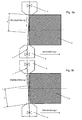
- the expiring wire 1 is - see FIGS. 3a, 3b - As said alternately inclined in at least two different specific angular positions in the cutting direction r. This is preferably done by relative displacement of the upper wire guide 4 relative to the lower wire guide 3.
- a wire electric discharge machine has X / Y axes, U / V axes, and a Z axis which adjusts the upper wire guide 4 from the lower one Wire guide 3 allow.
- the upper wire guide 4 is offset during a first period in the cutting direction relative to the lower wire guide 3 to the front, whereby the wire 1 is placed in a first specific angular position; During a second period of time, the upper wire guide 4 is set back relative to the lower wire guide 3, whereby the wire 1 is placed in a second specific angular position.
- Each particular angular position is adjusted during a certain period of time, so that the workpiece 2 can be processed in the respective angular position. This procedure is repeated as desired, the two different angular positions being set alternately.
- the X and / or Y axis may also be involved.
- the relative angular position between the wire and the workpiece must be changeable.
- the adjustment of the at least two different angular positions takes place on the workpiece, wherein the workpiece is pivoted about an axis normal to the plane defined by wire running direction and cutting direction.
- the workpiece is clamped for example on a commercial rotation axis, and is alternately brought into at least two different specific angular positions relative to the at least one wire.
- the embodiment described here with a rotation axis is particularly suitable for the pivoting of the workpiece in a single direction of rotation.
- the device for pivoting the workpiece is preferably adapted to the specific processing tasks.
- the device for pivoting the workpiece may also be specially designed, for example as a two-sided mounted nacelle for small pivoting angles.
- a pivotable work table for example, a work table with parallel kinematic according to "Design of hybrid-kinematic mechanism for machine tool” according to Patric Pham, thesis EPFL 4314, page 130 (http: // dx.doi.org/10.5075/epfl-thesis-4314).
- relatively small angular positions are set, for example, of +/- 2 °, so that otherwise cutting conditions similar to the so-called.
- Cylindrical section ie with vertically continuous wire.
- the process for changing over the angular position is interrupted for a short time, e.g. by generator shutdown, or at least the process parameters are reduced for a short time.
- this interruption or reduction is limited to a few 100ms.
- FW machines are particularly widespread in Asia, as the acquisition and maintenance costs are very low. In the traditional industrialized countries, FW machines have so far had almost no sales, mainly because the level of automation is very low and because they can not compete with those of the much more expensive WEDM machines in terms of performance.
- the following description refers essentially to WEDM and FW, but this is not meant to be limiting.
- the invention can be used particularly advantageously in connection with FW machines. Since in FW machines anyway a period of intermittent process to reverse the wire running direction is required, the relative angular position of the wire is preferably changed to the workpiece in the cutting direction at the same time.
- the FW machine typically has a wire supply of about 600m.
- the wire speed is about 10m / s, so that the wire direction reverses after about 60s. With a workpiece height of 100mm and a typical cut rate of 100mm 2 / min, the cutting speed is about 1mm / min. Thus, in each direction of wire running in each case about 1 mm of the 100mm high workpiece is cut.
- the FW wire running direction and angular position of the wire in the cutting direction are coordinated so that the wire when entering the kerf meets directly on the part height of the workpiece to be machined.
- the wire running direction I should be set so that the wire 1 from above to the workpiece 2 runs.
- the wire running direction I should be set so that the wire 1 from below to the workpiece 2 runs.
- the clean rinsing liquid succeeds rather at the site of action in the kerf.
- This measure can also be used in other wire cutting methods with reversing wire erection, for example, an abrasive cutting process with loose abrasive grain (slurry).
- the wire can be alternately inclined in at least two different angular positions.
- the pivoting devices described above can also be used.
- a device for adjusting a wire guide by a fixed amount is sufficient in the simplest form.
- the at least two different specific angular positions can already be set, namely, on the one hand, the vertical wire running direction (first angular position) and, on the other hand, a second angular position resulting from displacement of a wire guide.
- the invention is preferably used in straight contour sections because the wire pitch in the cutting direction in curved contour sections (radii and corners) is known to result in a contour error.
- the contour error depends on the current contour curvature, the angle of the wire and the height of the workpiece. The same relationships and constraints apply to the prior art mentioned in the introduction ( EP2223400 ) are extensively explained. If a certain contour error is tolerated, the method according to the invention can therefore also be used in the region of slightly curved contours.
- a process break is introduced. During this process break no material removal takes place. The changeover between the specific angular positions should therefore take place quickly.
- the periodic switching from one angular position to the other is preferably carried out with the maximum positioning speed; however, the wire should reach the respective target position without overshooting. Therefore, after a pause for switching the relative angular position of the wire to the workpiece, the wire is preferably not moved directly to the target position for resuming machining, but rather to a starting position which is, for example, 5 to 500 ⁇ m, typically 50 ⁇ m, before the target position.
- the end position ie, the position of the workpiece and / or the wire before a break to reverse the relative angular position of the wire to the workpiece, is stored at the same relative angular position in view of the following processing.
- the target position for resuming the machining corresponds to the end position of the wire at the end of the preceding cutting period at the same angular position.
- the new target position of the workpiece and / or the wire to resume processing after a break to change the relative angular position of the wire to the workpiece is determined by the stored end position of Workpiece and / or the wire in a previous processing phase at the same relative angular position determined. From the starting position, the wire preferably travels at a reduced speed to the destination position; in the case of wire-cutting, preferably with the maximum process-controlled speed.
- the wire is preferably inclined in two different angular positions in the cutting direction;
- the method according to the invention can also be realized with three or more different specific angular positions. In this way, the average effective cutting height of the number of different angular positions can be divided accordingly.
- the wire or the workpiece is alternately inclined in two different specific angular positions in the cutting direction, wherein the amount of the angle of inclination of the two angular positions relative to the workpiece or the vertical wire running direction is equal and the inclination directions are opposite.
- the wire or workpiece is tilted once forward in the cutting direction and once backwards in the cutting direction, for example by the same amount.
- FIGS. 4a to 4c show a non-exhaustive selection of possible wire pitch sequences.
- the cutting process begins and / or ends in the vertical wire running direction, wherein alternately the at least two different specific angular positions are set between the beginning and the end.
- FIG. 4a shows a wire pitch sequence in which the wire is initially in the vertical starting position A 0 ; then alternately a first angular position A 1 in the cutting direction and a second angular position A 2 is set in the cutting direction; the angular positions A 1 and A 2 are set alternately until the end of the machining or the contour section.
- FIG. 4b shows a wire pitch sequence with two specific angular positions, in which the wire is initially in the vertical position; the vertical wire running direction A 0 is here one of the two angular positions to be set; It is alternately set the first predetermined angular position A 0 in the cutting direction and a second predetermined angular position A 1 in the cutting direction.
- Figure 4c shows a further wire pitch sequence in which alternately three different specific angular positions are set in the cutting direction.
- FIGS. 5a to 5c show the course of the angular position to the vertical wire direction or the angle of inclination of the wire with respect to the vertical wire running direction ⁇ 0 as a function of time when setting a wire pitch sequence according to FIGS. 4a to 4c
- FIG. 5a as already related to FIG. 4a mentions a wire pitch sequence in which during the processing of a contour section alternately two different specific angular positions A 1 and A 2 are set.
- Each particular angular position is adjusted during a certain associated time period (t 1 , t 2 ) and the workpiece is machined in the respective predetermined angular position.
- the angular position A 1 is set with the inclination angle ⁇ 1 (here negative) during a time period t 1 .
- the wire is brought from an inclination angle ⁇ 1 to an inclination angle ⁇ 2 .
- the second angular position A 2 is held during a time t 2 . Subsequently, the process is repeated by the angular position A 1 is set again, etc.
- the length of time a certain angular position is set depends on several factors. In FW machines, the length of the wire supply is limited and the wire speed is relatively high. In reversing wire direction FW machines, the amount of time that a particular angular position is adjusted is preferably equal to the length of time between two turns of the wire-running direction. For machines with a very large supply of wire (e.g., several kilometers), the period of time during which a particular angular position is adjusted is preferably predetermined or calculated from the rate of cut.
- each time period (t 1 , t 2 , t 3 , ...) is optimized for each angular position with respect to a maximum cutting performance.
- at least the process break for the conversion of the angular position and the respective cutting power at each specific angular position are preferably taken into account.
- each time duration (t 1 , t 2 , t 3 ,...) is the same length, so that the machining proportion and the average effective cutting height at each angular position are substantially equal.
- the proportions of the machining in the at least two different specific angular positions need not necessarily be the same.
- the wire may be slanted over 3/5 of the time in a first predetermined angular position in the cutting direction, and inclined over 2/5 of the time in a second predetermined angular position in the cutting direction. This can i.a. be advantageous where the cutting performance at the two different specific angular positions is different, for example, if there are inhomogeneous cutting conditions on the workpiece height.
- FIGS. 6a to 6c each show an illustration of the sectional plane of a workpiece in the adjustment of the angular position of the wire according to the FIGS. 4a to 4c ,
- the recognizable pattern shows the areas over which a certain angular position has been set.
- FIG. 6c shows three different angular positions and two transition areas.
- FIGS. 6a to 6c is also the over the period (t 1 , t 2 , t 3 , ...) changing engagement height on the workpiece recognizable, ie the effective cutting height on the workpiece at the respective angular position.
- FIG. 6d shows an enlargement of a window FIG. 6a .
- the effective cutting height is smallest at the beginning of a sub-period (h 1a , h 2a ) and increases steadily until the end of the sub-period (h 1b , h 2b ).
- the average effective cutting height at the workpiece is equal to half the sum of h 1b and h 2b .
- the difference ⁇ h between the minimum and the maximum engagement height on the workpiece is given by the time during which a certain angular position is set, by the amount and direction of the angular positions and by the cutting rate.
- ⁇ h should not be too large for the machining conditions to change much over a period of time during which a particular angular position is adjusted.
- a suitable angular position can thus be derived and set, for example, on the basis of the expected cutting rate and a permissible difference ⁇ h .
- FIG. 7b shows the course of the wire speed over time in a machine with reversing wire direction, for example, a FW machine.
- the wire speed is zero at the beginning; then the wire speed v 1 is set and held for a first period of time; Subsequently, the wire running direction is switched and it is set during a second period of wire speed v 2 .
- the two wire running directions are set alternately.
- FIG. 7c shows the connection of a pulse generator as a function of time, or the shutdown during a process break.
- the Figure 7a shows a graphical representation of the angular position or the inclination angle as a function of time; Figure 7a corresponds to the one described above FIG. 5a ,
- the change of the angular position is preferably carried out simultaneously with the switching of the wire running direction, since the processing is stopped during the switching anyway.
- the control program can preferably determine automatically whether the inventive wire cutting method is advantageously applicable.
- the expected cutting rates when used for the cutting method according to the invention are compared with the cutting rates for traditional cutting methods.
- the expected cutting rates are stored, for example in function of the material and / or the workpiece height, for example in the form of tables in a memory of the machine control.
- other comparison criteria for example target parameters such as surface quality, contour accuracy, etc. are also stored.
- the inventive wire cutting method is combined with a multi-wire system, for example with a multi-wire system in which a wire is deflected and guided multiple times, such that two or more wire sections of the same wire are brought parallel to the workpiece and that the workpiece is processed simultaneously in several places, or in another example, with a multiwire system in which multiple independent wires are brought in parallel to the workpiece and that the workpiece is simultaneously processed at multiple locations.
- the invention is preferably suitable for the so-called full section (also main section). Particularly suitable is the method for easy separation with a particular cutting direction.
- the invention can be used advantageously in particular for large workpiece height; At WEDM, an interesting increase in the cutting rate can be expected, especially from around 150mm. For special materials with poor conductivity (semiconductors, quartz, ceramics, etc.) an increase in the cutting rate is possible even with a smaller workpiece height.
Landscapes
- Engineering & Computer Science (AREA)
- Mechanical Engineering (AREA)
- Chemical & Material Sciences (AREA)
- Life Sciences & Earth Sciences (AREA)
- Forests & Forestry (AREA)
- Chemical Kinetics & Catalysis (AREA)
- Electrochemistry (AREA)
- Materials Engineering (AREA)
- Metallurgy (AREA)
- Organic Chemistry (AREA)
- Electrical Discharge Machining, Electrochemical Machining, And Combined Machining (AREA)
- Processing Of Stones Or Stones Resemblance Materials (AREA)
Claims (16)
- Procédé pour couper une pièce (2) au moyen d'un fil en défilement (1), dans lequel le fil (1) et/ou la pièce (2) sont inclinés l'un par rapport à l'autre alternativement dans au moins deux positions angulaires déterminées différentes dans la direction de coupe (r), caractérisé en ce qu'en raison des positions angulaires déterminées différentes la hauteur de coupe effective (s) sur la pièce (2) est plus petite que la hauteur totale (h) de la pièce, dans lequel on introduit une pause du processus, pendant laquelle il ne se produit aucun enlèvement de matière, pour l'inversion des positions angulaires déterminées.
- Procédé selon la revendication 1, caractérisé en ce que chaque position angulaire déterminée est réglée dans la direction de coupe (r) pendant une durée associée déterminée (t1, t2, t3), et en ce que la pièce (2) est usinée dans la position angulaire respective.
- Procédé selon la revendication 2, caractérisé en ce que la durée pour chaque position angulaire déterminée dans la direction de coupe (r) est optimisée dans l'optique d'une puissance de coupe maximale.
- Procédé selon l'une quelconque des revendications précédentes, caractérisé en ce que, pour le réglage des au moins deux positions angulaires déterminées différentes dans la direction de coupe (r), un guide-fil inférieur (3) et/ou un guide-fil supérieur (4) est/sont déplacé(s) l'un par rapport à l'autre dans la direction de coupe.
- Procédé selon l'une quelconque des revendications précédentes, caractérisé en ce que, pour le réglage des au moins deux positions angulaires déterminées différentes dans la direction de coupe (r), la pièce (2) est basculée autour d'un axe normal au plan défini par la direction de défilement du fil et la direction de coupe.
- Procédé selon l'une quelconque des revendications précédentes, caractérisé en ce qu'une première des au moins deux positions angulaires déterminées différentes dans la direction de coupe (r) est la direction verticale de défilement du fil.
- Procédé selon l'une quelconque des revendications précédentes, caractérisé en ce que le fil (1) et/ou la pièce (2) sont inclinés l'un par rapport à l'autre dans la direction de coupe (r) alternativement dans deux positions angulaires déterminées différentes, dans lequel la valeur de l'angle d'inclinaison des deux positions angulaires déterminées est égal et les directions d'inclinaison sont opposées.
- Procédé selon l'une quelconque des revendications précédentes, caractérisé en ce que la direction de défilement du fil (1) du fil est inversée en alternance et en ce que la position angulaire relative du fil par rapport à la pièce est modifiée pendant l'inversion de la direction de défilement du fil (1).
- Procédé selon l'une quelconque des revendications précédentes, caractérisé en ce que la direction de défilement du fil (1) et la position angulaire relative du fil dans la direction de coupe (r) sont accordées l'une à l'autre, de telle manière que, lors de son entrée dans la fente de coupe, le fil arrive directement sur la région de coupe à usiner de la pièce.
- Procédé selon l'une quelconque des revendications précédentes, caractérisé en ce qu'une position d'extrémité de la pièce (2) et/ou du fil (1) avant une pause pour l'inversion de la position angulaire relative du fil (1) par rapport à la pièce (2) est mémorisée dans l'optique de l'usinage suivant dans la même position angulaire relative.
- Procédé selon la revendication 10, caractérisé en ce que l'on détermine une position cible de la pièce (2) et/ou du fil (1) pour la reprise de l'usinage après une pause pour l'inversion de la position angulaire relative du fil (1) par rapport à la pièce (2) par la position d'extrémité mémorisée de la pièce et/ou du fil (1) dans une phase d'usinage antérieure dans la même position angulaire relative.
- Procédé selon la revendication 11, caractérisé en ce que l'on détermine une position de départ, qui est reculée dans la direction de coupe (r) d'une valeur déterminée, en particulier de 5 à 500 µm, par rapport à la position cible pour la reprise de l'usinage.
- Procédé selon la revendication 12, caractérisé en ce que l'inversion de la position angulaire relative du fil (1) par rapport à la pièce (2) jusqu'à la position de départ est effectuée avec une vitesse de positionnement maximale et en ce que la position pour la reprise de l'usinage est effectuée avec une vitesse commandée par le processus.
- Procédé selon l'une quelconque des revendications précédentes, caractérisé en ce que le fil (1) est dévié et guidé plusieurs fois, de telle manière que deux ou plus de deux tronçons de fil soient amenés à la pièce (2) parallèlement l'un à l'autre et en ce que la pièce (2) est usinée simultanément en plusieurs endroits.
- Procédé selon l'une quelconque des revendications précédentes, caractérisé en ce que plusieurs fils sont amenés à la pièce (2) parallèlement l'un à l'autre et en ce que la pièce (2) est usinée simultanément en plusieurs endroits.
- Procédé selon l'une quelconque des revendications précédentes, caractérisé en ce que l'enlèvement de matière est effectué par usinage électroérosif, électrochimique et/ou abrasif.
Applications Claiming Priority (1)
| Application Number | Priority Date | Filing Date | Title |
|---|---|---|---|
| CH20612011 | 2011-12-30 |
Publications (2)
| Publication Number | Publication Date |
|---|---|
| EP2610026A1 EP2610026A1 (fr) | 2013-07-03 |
| EP2610026B1 true EP2610026B1 (fr) | 2015-11-18 |
Family
ID=47323995
Family Applications (1)
| Application Number | Title | Priority Date | Filing Date |
|---|---|---|---|
| EP12197230.1A Active EP2610026B1 (fr) | 2011-12-30 | 2012-12-14 | Procédé de coupe à fil |
Country Status (4)
| Country | Link |
|---|---|
| US (1) | US9193020B2 (fr) |
| EP (1) | EP2610026B1 (fr) |
| CN (1) | CN103182575B (fr) |
| ES (1) | ES2560631T3 (fr) |
Cited By (1)
| Publication number | Priority date | Publication date | Assignee | Title |
|---|---|---|---|---|
| CN110142471A (zh) * | 2019-07-02 | 2019-08-20 | 哈尔滨工业大学 | 绝缘陶瓷涂层-金属电火花加工的异常放电状态检测装置和方法 |
Families Citing this family (10)
| Publication number | Priority date | Publication date | Assignee | Title |
|---|---|---|---|---|
| JP5369205B2 (ja) * | 2012-02-27 | 2013-12-18 | ファナック株式会社 | 切込み加工時、逃げ加工時の加工傷を低減するワイヤ放電加工機およびワイヤ放電加工方法 |
| KR101508840B1 (ko) * | 2013-08-14 | 2015-04-06 | 삼성전기주식회사 | 재단 소결 세라믹 시트 및 그 제조방법 |
| US9573284B2 (en) * | 2014-01-15 | 2017-02-21 | Southwest Research Institute | Method and apparatus to propagate crack growth in a workpiece |
| WO2015145529A1 (fr) | 2014-03-24 | 2015-10-01 | 三菱電機株式会社 | Appareil d'usinage et procédé d'usinage par décharge électrique à fil |
| CN104325489B (zh) * | 2014-10-15 | 2017-01-11 | 成都东方凯特瑞环保催化剂有限责任公司 | 一种软态坯料切割方法及其切割装置 |
| JP6374451B2 (ja) * | 2016-07-27 | 2018-08-15 | ファナック株式会社 | ワイヤ放電加工機及びワイヤ放電加工方法 |
| EP3360636B1 (fr) * | 2017-02-14 | 2024-06-12 | Agie Charmilles SA | Appareil de découpe de fil et procédé pour séparer des parties d'une plaque de base au moyen d'un appareil de découpe de fil |
| US10987745B2 (en) | 2019-01-25 | 2021-04-27 | Snap-On Incorporated | Method of manufacturing socket punches |
| CN116572403A (zh) * | 2023-06-12 | 2023-08-11 | 泉州市大鲨鱼机械科技有限公司 | 一种绳锯切割方法 |
| CN116572402A (zh) * | 2023-06-12 | 2023-08-11 | 泉州市大鲨鱼机械科技有限公司 | 一种绳锯机装置 |
Family Cites Families (12)
| Publication number | Priority date | Publication date | Assignee | Title |
|---|---|---|---|---|
| JPS62114828A (ja) | 1985-11-14 | 1987-05-26 | Fanuc Ltd | ワイヤカツト放電加工方法及び装置 |
| JPH0635107B2 (ja) * | 1987-12-26 | 1994-05-11 | 株式会社タカトリハイテック | ワイヤソー |
| JP3057906B2 (ja) | 1992-05-22 | 2000-07-04 | 株式会社ソディック | ワイヤ放電加工方法 |
| DE19932645C5 (de) * | 1999-07-13 | 2007-01-11 | Agie S.A., Losone | Funkenerosionsmaschine und Modulsatz für den Zusammenbau von Werkzeugmaschinen, insbesondere Funkenerosionsmaschinen |
| CH697024A5 (fr) * | 2000-09-28 | 2008-03-31 | Hct Shaping Systems Sa | Dispositif de sciage par fil. |
| JP4629393B2 (ja) * | 2004-09-10 | 2011-02-09 | 三菱電機株式会社 | ワイヤ放電加工装置 |
| GB0724286D0 (en) | 2007-12-12 | 2008-01-30 | Aker Kvaerner Subsea Ltd | Subsea containment vessel and heat sink assembly |
| JP2009226504A (ja) * | 2008-03-19 | 2009-10-08 | Mitsubishi Electric Corp | ワイヤ放電加工装置 |
| ES2427014T3 (es) | 2009-01-29 | 2013-10-28 | Agie Charmilles Sa | Método y aparato de mecanizado por descarga eléctrica por hilo metálico |
| JP4712887B2 (ja) * | 2009-09-11 | 2011-06-29 | ファナック株式会社 | ワイヤカット放電加工方法、およびその装置、並びに、ワイヤカット放電加工用プログラム作成装置、および、ワイヤカット放電加工用プログラムを作成するプログラムを記録したコンピュータ読み取り可能な記録媒体 |
| CN101780571A (zh) * | 2010-03-16 | 2010-07-21 | 赵红九 | 线切割环形电极丝的储存运行装置和单向走丝线切割机 |
| CN102069250B (zh) * | 2011-01-21 | 2012-11-14 | 华东交通大学 | 电火花线切割机床组合穿孔装置及穿孔工艺 |
-
2012
- 2012-12-14 EP EP12197230.1A patent/EP2610026B1/fr active Active
- 2012-12-14 ES ES12197230.1T patent/ES2560631T3/es active Active
- 2012-12-26 US US13/727,169 patent/US9193020B2/en not_active Expired - Fee Related
- 2012-12-28 CN CN201210592144.1A patent/CN103182575B/zh active Active
Cited By (1)
| Publication number | Priority date | Publication date | Assignee | Title |
|---|---|---|---|---|
| CN110142471A (zh) * | 2019-07-02 | 2019-08-20 | 哈尔滨工业大学 | 绝缘陶瓷涂层-金属电火花加工的异常放电状态检测装置和方法 |
Also Published As
| Publication number | Publication date |
|---|---|
| EP2610026A1 (fr) | 2013-07-03 |
| US20130180866A1 (en) | 2013-07-18 |
| ES2560631T3 (es) | 2016-02-22 |
| US9193020B2 (en) | 2015-11-24 |
| CN103182575B (zh) | 2017-04-12 |
| CN103182575A (zh) | 2013-07-03 |
Similar Documents
| Publication | Publication Date | Title |
|---|---|---|
| EP2610026B1 (fr) | Procédé de coupe à fil | |
| DE112011103905B4 (de) | Drahtschneideelektroerodierverfahren und Halbleiterwaferherstellungsverfahren | |
| EP2374569B1 (fr) | Dispositif de traitement au laser et procédé de fabrication d'un outil à rotation symétrique | |
| EP3027345B2 (fr) | Procédé d'usinage des arêtes de dents et station d'usinage pour mettre en oeuvre ledit procédé | |
| DE2408715C2 (de) | Spülvorrichtung für die elektroerosive Bearbeitung elektrisch leitender Werkstoffe | |
| DE112014006901T5 (de) | Elektrische Drahterodiervorrichtung und Verfahren zur Herstellung eines Halbleiterwafers | |
| DE2828168A1 (de) | Numerisch steuerbare schleifmaschine | |
| EP2308638A1 (fr) | Machine de traitement dur et fin pour le traitement dur et fin d'une pièce usinée | |
| DE112016006887B4 (de) | Drahterodiermaschine, Führungsbaugruppe und Drahterodierverfahren | |
| DE19710458B4 (de) | Verfahren zum funkenerosiven Bearbeiten | |
| EP2839917B1 (fr) | Machine d'électro-érosion ayant un dispositif pour l'enfilage du fil-électrode | |
| DE3405424C2 (fr) | ||
| DE3203605A1 (de) | Verfahren und vorrichtung zum elektroerosiven bearbeiten eines profils in einem werkstueck | |
| EP0585715B1 (fr) | Procédé, dispositif et fil pour le découpage par électroérosion | |
| EP3290142A1 (fr) | Procédé et dispositif de détermination de l'usure d'electrodes lors de l'electro-érosion | |
| EP1093878A1 (fr) | Optimisation des paramètres d'usinage pour machine d'usinage par électroérosion | |
| DE2131633A1 (de) | Suspensionssieb und Verfahren zu seiner Herstellung | |
| EP1518631B1 (fr) | Méthode pour le reformage et/ou l'enlèvement de dépôts, en particulier pour les électrodes de soudage par résistance. | |
| EP3291939B1 (fr) | Érosion de la denture intérieure sur des extrudeuses planétaires | |
| DE3814675A1 (de) | Bearbeitungsverfahren zum planetaererodieren | |
| DE3340388A1 (de) | Funkenerosionsverfahren und -einrichtung mit bewegter drahtelektrode | |
| EP0503509B1 (fr) | Méthode de coupe par fil électro-érosif | |
| DE19654964B4 (de) | Vorrichtung und Verfahren zur Funkenerosionsbearbeitung | |
| WO2025172279A1 (fr) | Procédé et machine-outil destinés à la fabrication d'un outil de dressage ainsi qu'outil de dressage | |
| EP1419840A1 (fr) | Dispositif d'usinage, notamment de rabotage, des bords d'un matériel en forme de bande et procédé de soudage de laser |
Legal Events
| Date | Code | Title | Description |
|---|---|---|---|
| PUAI | Public reference made under article 153(3) epc to a published international application that has entered the european phase |
Free format text: ORIGINAL CODE: 0009012 |
|
| AK | Designated contracting states |
Kind code of ref document: A1 Designated state(s): AL AT BE BG CH CY CZ DE DK EE ES FI FR GB GR HR HU IE IS IT LI LT LU LV MC MK MT NL NO PL PT RO RS SE SI SK SM TR |
|
| AX | Request for extension of the european patent |
Extension state: BA ME |
|
| 17P | Request for examination filed |
Effective date: 20131127 |
|
| RBV | Designated contracting states (corrected) |
Designated state(s): AL AT BE BG CH CY CZ DE DK EE ES FI FR GB GR HR HU IE IS IT LI LT LU LV MC MK MT NL NO PL PT RO RS SE SI SK SM TR |
|
| GRAP | Despatch of communication of intention to grant a patent |
Free format text: ORIGINAL CODE: EPIDOSNIGR1 |
|
| INTG | Intention to grant announced |
Effective date: 20150722 |
|
| GRAS | Grant fee paid |
Free format text: ORIGINAL CODE: EPIDOSNIGR3 |
|
| GRAA | (expected) grant |
Free format text: ORIGINAL CODE: 0009210 |
|
| AK | Designated contracting states |
Kind code of ref document: B1 Designated state(s): AL AT BE BG CH CY CZ DE DK EE ES FI FR GB GR HR HU IE IS IT LI LT LU LV MC MK MT NL NO PL PT RO RS SE SI SK SM TR |
|
| REG | Reference to a national code |
Ref country code: GB Ref legal event code: FG4D Free format text: NOT ENGLISH |
|
| REG | Reference to a national code |
Ref country code: CH Ref legal event code: NV Representative=s name: GEORG FISCHER AG, CH Ref country code: CH Ref legal event code: EP |
|
| REG | Reference to a national code |
Ref country code: AT Ref legal event code: REF Ref document number: 761268 Country of ref document: AT Kind code of ref document: T Effective date: 20151215 |
|
| REG | Reference to a national code |
Ref country code: IE Ref legal event code: FG4D Free format text: LANGUAGE OF EP DOCUMENT: GERMAN |
|
| REG | Reference to a national code |
Ref country code: FR Ref legal event code: PLFP Year of fee payment: 4 |
|
| REG | Reference to a national code |
Ref country code: DE Ref legal event code: R096 Ref document number: 502012005239 Country of ref document: DE |
|
| REG | Reference to a national code |
Ref country code: ES Ref legal event code: FG2A Ref document number: 2560631 Country of ref document: ES Kind code of ref document: T3 Effective date: 20160222 |
|
| REG | Reference to a national code |
Ref country code: NL Ref legal event code: MP Effective date: 20160218 |
|
| REG | Reference to a national code |
Ref country code: LT Ref legal event code: MG4D |
|
| PG25 | Lapsed in a contracting state [announced via postgrant information from national office to epo] |
Ref country code: LT Free format text: LAPSE BECAUSE OF FAILURE TO SUBMIT A TRANSLATION OF THE DESCRIPTION OR TO PAY THE FEE WITHIN THE PRESCRIBED TIME-LIMIT Effective date: 20151118 Ref country code: IS Free format text: LAPSE BECAUSE OF FAILURE TO SUBMIT A TRANSLATION OF THE DESCRIPTION OR TO PAY THE FEE WITHIN THE PRESCRIBED TIME-LIMIT Effective date: 20160318 Ref country code: NO Free format text: LAPSE BECAUSE OF FAILURE TO SUBMIT A TRANSLATION OF THE DESCRIPTION OR TO PAY THE FEE WITHIN THE PRESCRIBED TIME-LIMIT Effective date: 20160218 Ref country code: HR Free format text: LAPSE BECAUSE OF FAILURE TO SUBMIT A TRANSLATION OF THE DESCRIPTION OR TO PAY THE FEE WITHIN THE PRESCRIBED TIME-LIMIT Effective date: 20151118 Ref country code: NL Free format text: LAPSE BECAUSE OF FAILURE TO SUBMIT A TRANSLATION OF THE DESCRIPTION OR TO PAY THE FEE WITHIN THE PRESCRIBED TIME-LIMIT Effective date: 20151118 |
|
| PG25 | Lapsed in a contracting state [announced via postgrant information from national office to epo] |
Ref country code: GR Free format text: LAPSE BECAUSE OF FAILURE TO SUBMIT A TRANSLATION OF THE DESCRIPTION OR TO PAY THE FEE WITHIN THE PRESCRIBED TIME-LIMIT Effective date: 20160219 Ref country code: PT Free format text: LAPSE BECAUSE OF FAILURE TO SUBMIT A TRANSLATION OF THE DESCRIPTION OR TO PAY THE FEE WITHIN THE PRESCRIBED TIME-LIMIT Effective date: 20160318 Ref country code: PL Free format text: LAPSE BECAUSE OF FAILURE TO SUBMIT A TRANSLATION OF THE DESCRIPTION OR TO PAY THE FEE WITHIN THE PRESCRIBED TIME-LIMIT Effective date: 20151118 Ref country code: SE Free format text: LAPSE BECAUSE OF FAILURE TO SUBMIT A TRANSLATION OF THE DESCRIPTION OR TO PAY THE FEE WITHIN THE PRESCRIBED TIME-LIMIT Effective date: 20151118 Ref country code: BE Free format text: LAPSE BECAUSE OF NON-PAYMENT OF DUE FEES Effective date: 20151231 Ref country code: LV Free format text: LAPSE BECAUSE OF FAILURE TO SUBMIT A TRANSLATION OF THE DESCRIPTION OR TO PAY THE FEE WITHIN THE PRESCRIBED TIME-LIMIT Effective date: 20151118 Ref country code: RS Free format text: LAPSE BECAUSE OF FAILURE TO SUBMIT A TRANSLATION OF THE DESCRIPTION OR TO PAY THE FEE WITHIN THE PRESCRIBED TIME-LIMIT Effective date: 20151118 Ref country code: FI Free format text: LAPSE BECAUSE OF FAILURE TO SUBMIT A TRANSLATION OF THE DESCRIPTION OR TO PAY THE FEE WITHIN THE PRESCRIBED TIME-LIMIT Effective date: 20151118 |
|
| PG25 | Lapsed in a contracting state [announced via postgrant information from national office to epo] |
Ref country code: CZ Free format text: LAPSE BECAUSE OF FAILURE TO SUBMIT A TRANSLATION OF THE DESCRIPTION OR TO PAY THE FEE WITHIN THE PRESCRIBED TIME-LIMIT Effective date: 20151118 |
|
| REG | Reference to a national code |
Ref country code: DE Ref legal event code: R097 Ref document number: 502012005239 Country of ref document: DE |
|
| PG25 | Lapsed in a contracting state [announced via postgrant information from national office to epo] |
Ref country code: RO Free format text: LAPSE BECAUSE OF FAILURE TO SUBMIT A TRANSLATION OF THE DESCRIPTION OR TO PAY THE FEE WITHIN THE PRESCRIBED TIME-LIMIT Effective date: 20151118 Ref country code: EE Free format text: LAPSE BECAUSE OF FAILURE TO SUBMIT A TRANSLATION OF THE DESCRIPTION OR TO PAY THE FEE WITHIN THE PRESCRIBED TIME-LIMIT Effective date: 20151118 Ref country code: DK Free format text: LAPSE BECAUSE OF FAILURE TO SUBMIT A TRANSLATION OF THE DESCRIPTION OR TO PAY THE FEE WITHIN THE PRESCRIBED TIME-LIMIT Effective date: 20151118 Ref country code: SM Free format text: LAPSE BECAUSE OF FAILURE TO SUBMIT A TRANSLATION OF THE DESCRIPTION OR TO PAY THE FEE WITHIN THE PRESCRIBED TIME-LIMIT Effective date: 20151118 Ref country code: SK Free format text: LAPSE BECAUSE OF FAILURE TO SUBMIT A TRANSLATION OF THE DESCRIPTION OR TO PAY THE FEE WITHIN THE PRESCRIBED TIME-LIMIT Effective date: 20151118 |
|
| REG | Reference to a national code |
Ref country code: IE Ref legal event code: MM4A |
|
| PLBE | No opposition filed within time limit |
Free format text: ORIGINAL CODE: 0009261 |
|
| STAA | Information on the status of an ep patent application or granted ep patent |
Free format text: STATUS: NO OPPOSITION FILED WITHIN TIME LIMIT |
|
| PG25 | Lapsed in a contracting state [announced via postgrant information from national office to epo] |
Ref country code: MC Free format text: LAPSE BECAUSE OF FAILURE TO SUBMIT A TRANSLATION OF THE DESCRIPTION OR TO PAY THE FEE WITHIN THE PRESCRIBED TIME-LIMIT Effective date: 20151118 |
|
| 26N | No opposition filed |
Effective date: 20160819 |
|
| PG25 | Lapsed in a contracting state [announced via postgrant information from national office to epo] |
Ref country code: IE Free format text: LAPSE BECAUSE OF NON-PAYMENT OF DUE FEES Effective date: 20151214 |
|
| PG25 | Lapsed in a contracting state [announced via postgrant information from national office to epo] |
Ref country code: SI Free format text: LAPSE BECAUSE OF FAILURE TO SUBMIT A TRANSLATION OF THE DESCRIPTION OR TO PAY THE FEE WITHIN THE PRESCRIBED TIME-LIMIT Effective date: 20151118 |
|
| REG | Reference to a national code |
Ref country code: FR Ref legal event code: PLFP Year of fee payment: 5 |
|
| PG25 | Lapsed in a contracting state [announced via postgrant information from national office to epo] |
Ref country code: BG Free format text: LAPSE BECAUSE OF FAILURE TO SUBMIT A TRANSLATION OF THE DESCRIPTION OR TO PAY THE FEE WITHIN THE PRESCRIBED TIME-LIMIT Effective date: 20151118 Ref country code: HU Free format text: LAPSE BECAUSE OF FAILURE TO SUBMIT A TRANSLATION OF THE DESCRIPTION OR TO PAY THE FEE WITHIN THE PRESCRIBED TIME-LIMIT; INVALID AB INITIO Effective date: 20121214 |
|
| PG25 | Lapsed in a contracting state [announced via postgrant information from national office to epo] |
Ref country code: CY Free format text: LAPSE BECAUSE OF FAILURE TO SUBMIT A TRANSLATION OF THE DESCRIPTION OR TO PAY THE FEE WITHIN THE PRESCRIBED TIME-LIMIT Effective date: 20151118 |
|
| PG25 | Lapsed in a contracting state [announced via postgrant information from national office to epo] |
Ref country code: MT Free format text: LAPSE BECAUSE OF FAILURE TO SUBMIT A TRANSLATION OF THE DESCRIPTION OR TO PAY THE FEE WITHIN THE PRESCRIBED TIME-LIMIT Effective date: 20151118 |
|
| PG25 | Lapsed in a contracting state [announced via postgrant information from national office to epo] |
Ref country code: LU Free format text: LAPSE BECAUSE OF NON-PAYMENT OF DUE FEES Effective date: 20151214 |
|
| REG | Reference to a national code |
Ref country code: FR Ref legal event code: PLFP Year of fee payment: 6 |
|
| PG25 | Lapsed in a contracting state [announced via postgrant information from national office to epo] |
Ref country code: TR Free format text: LAPSE BECAUSE OF FAILURE TO SUBMIT A TRANSLATION OF THE DESCRIPTION OR TO PAY THE FEE WITHIN THE PRESCRIBED TIME-LIMIT Effective date: 20151118 Ref country code: MK Free format text: LAPSE BECAUSE OF FAILURE TO SUBMIT A TRANSLATION OF THE DESCRIPTION OR TO PAY THE FEE WITHIN THE PRESCRIBED TIME-LIMIT Effective date: 20151118 |
|
| PG25 | Lapsed in a contracting state [announced via postgrant information from national office to epo] |
Ref country code: AL Free format text: LAPSE BECAUSE OF FAILURE TO SUBMIT A TRANSLATION OF THE DESCRIPTION OR TO PAY THE FEE WITHIN THE PRESCRIBED TIME-LIMIT Effective date: 20151118 |
|
| REG | Reference to a national code |
Ref country code: AT Ref legal event code: MM01 Ref document number: 761268 Country of ref document: AT Kind code of ref document: T Effective date: 20171214 |
|
| PG25 | Lapsed in a contracting state [announced via postgrant information from national office to epo] |
Ref country code: AT Free format text: LAPSE BECAUSE OF NON-PAYMENT OF DUE FEES Effective date: 20171214 |
|
| PGFP | Annual fee paid to national office [announced via postgrant information from national office to epo] |
Ref country code: IT Payment date: 20191230 Year of fee payment: 8 Ref country code: FR Payment date: 20191220 Year of fee payment: 8 |
|
| PGFP | Annual fee paid to national office [announced via postgrant information from national office to epo] |
Ref country code: ES Payment date: 20200121 Year of fee payment: 8 Ref country code: GB Payment date: 20191220 Year of fee payment: 8 |
|
| GBPC | Gb: european patent ceased through non-payment of renewal fee |
Effective date: 20201214 |
|
| PG25 | Lapsed in a contracting state [announced via postgrant information from national office to epo] |
Ref country code: FR Free format text: LAPSE BECAUSE OF NON-PAYMENT OF DUE FEES Effective date: 20201231 Ref country code: IT Free format text: LAPSE BECAUSE OF NON-PAYMENT OF DUE FEES Effective date: 20201214 |
|
| PG25 | Lapsed in a contracting state [announced via postgrant information from national office to epo] |
Ref country code: GB Free format text: LAPSE BECAUSE OF NON-PAYMENT OF DUE FEES Effective date: 20201214 |
|
| REG | Reference to a national code |
Ref country code: ES Ref legal event code: FD2A Effective date: 20220412 |
|
| PG25 | Lapsed in a contracting state [announced via postgrant information from national office to epo] |
Ref country code: ES Free format text: LAPSE BECAUSE OF NON-PAYMENT OF DUE FEES Effective date: 20201215 |
|
| P01 | Opt-out of the competence of the unified patent court (upc) registered |
Effective date: 20230529 |
|
| REG | Reference to a national code |
Ref country code: CH Ref legal event code: U11 Free format text: ST27 STATUS EVENT CODE: U-0-0-U10-U11 (AS PROVIDED BY THE NATIONAL OFFICE) Effective date: 20260101 |
|
| PGFP | Annual fee paid to national office [announced via postgrant information from national office to epo] |
Ref country code: DE Payment date: 20251211 Year of fee payment: 14 |
|
| PGFP | Annual fee paid to national office [announced via postgrant information from national office to epo] |
Ref country code: CH Payment date: 20260101 Year of fee payment: 14 |