EP2610040A1 - Mischvorrichtung und -verfahren für die Herstellung von Verbundstoffmaterial - Google Patents
Mischvorrichtung und -verfahren für die Herstellung von Verbundstoffmaterial Download PDFInfo
- Publication number
- EP2610040A1 EP2610040A1 EP13150053.0A EP13150053A EP2610040A1 EP 2610040 A1 EP2610040 A1 EP 2610040A1 EP 13150053 A EP13150053 A EP 13150053A EP 2610040 A1 EP2610040 A1 EP 2610040A1
- Authority
- EP
- European Patent Office
- Prior art keywords
- mixing chamber
- lining
- mixing
- rotor
- curing
- Prior art date
- Legal status (The legal status is an assumption and is not a legal conclusion. Google has not performed a legal analysis and makes no representation as to the accuracy of the status listed.)
- Withdrawn
Links
- 238000002156 mixing Methods 0.000 title claims abstract description 207
- 238000000034 method Methods 0.000 title claims abstract description 37
- 239000002131 composite material Substances 0.000 title claims abstract description 33
- 238000004519 manufacturing process Methods 0.000 title abstract description 8
- 239000004814 polyurethane Substances 0.000 claims abstract description 56
- 229920002635 polyurethane Polymers 0.000 claims abstract description 52
- 239000000203 mixture Substances 0.000 claims abstract description 37
- 241001669679 Eleotris Species 0.000 claims abstract description 25
- 239000004615 ingredient Substances 0.000 claims abstract description 24
- 229920003023 plastic Polymers 0.000 claims abstract description 23
- 239000004033 plastic Substances 0.000 claims abstract description 23
- 239000011343 solid material Substances 0.000 claims abstract description 19
- 239000008187 granular material Substances 0.000 claims abstract description 17
- 239000008240 homogeneous mixture Substances 0.000 claims description 29
- 150000003077 polyols Chemical class 0.000 claims description 27
- 239000000463 material Substances 0.000 claims description 24
- 229920005862 polyol Polymers 0.000 claims description 24
- 229910052751 metal Inorganic materials 0.000 claims description 14
- 239000002184 metal Substances 0.000 claims description 14
- 229920001228 polyisocyanate Polymers 0.000 claims description 14
- 239000005056 polyisocyanate Substances 0.000 claims description 14
- -1 polyethylene Polymers 0.000 claims description 9
- 239000004743 Polypropylene Substances 0.000 claims description 5
- 238000000227 grinding Methods 0.000 claims description 5
- 229920001155 polypropylene Polymers 0.000 claims description 5
- 238000004873 anchoring Methods 0.000 claims description 4
- 229920001343 polytetrafluoroethylene Polymers 0.000 claims description 4
- 239000004810 polytetrafluoroethylene Substances 0.000 claims description 4
- 239000002699 waste material Substances 0.000 claims description 4
- 241000283690 Bos taurus Species 0.000 claims description 2
- 239000004698 Polyethylene Substances 0.000 claims description 2
- 229920000573 polyethylene Polymers 0.000 claims description 2
- 229920001296 polysiloxane Polymers 0.000 claims description 2
- 238000007493 shaping process Methods 0.000 claims description 2
- 239000002245 particle Substances 0.000 description 19
- 230000008901 benefit Effects 0.000 description 15
- 239000012948 isocyanate Substances 0.000 description 12
- 150000002513 isocyanates Chemical class 0.000 description 12
- 239000004567 concrete Substances 0.000 description 10
- 239000000314 lubricant Substances 0.000 description 9
- 239000002023 wood Substances 0.000 description 8
- 238000004140 cleaning Methods 0.000 description 7
- 229920001187 thermosetting polymer Polymers 0.000 description 6
- 239000011230 binding agent Substances 0.000 description 5
- 238000001035 drying Methods 0.000 description 5
- 239000000835 fiber Substances 0.000 description 5
- 239000007787 solid Substances 0.000 description 5
- 238000009434 installation Methods 0.000 description 4
- 239000003921 oil Substances 0.000 description 4
- 239000000047 product Substances 0.000 description 4
- 238000011282 treatment Methods 0.000 description 4
- 229910000831 Steel Inorganic materials 0.000 description 3
- 230000009471 action Effects 0.000 description 3
- 238000006243 chemical reaction Methods 0.000 description 3
- 238000013461 design Methods 0.000 description 3
- 230000000694 effects Effects 0.000 description 3
- 239000004570 mortar (masonry) Substances 0.000 description 3
- 238000004064 recycling Methods 0.000 description 3
- 239000010959 steel Substances 0.000 description 3
- 239000000126 substance Substances 0.000 description 3
- 230000006978 adaptation Effects 0.000 description 2
- 230000005540 biological transmission Effects 0.000 description 2
- 229910052799 carbon Inorganic materials 0.000 description 2
- 239000000919 ceramic Substances 0.000 description 2
- 239000013043 chemical agent Substances 0.000 description 2
- 150000001875 compounds Chemical class 0.000 description 2
- 238000005260 corrosion Methods 0.000 description 2
- 230000007797 corrosion Effects 0.000 description 2
- 238000000354 decomposition reaction Methods 0.000 description 2
- 238000011049 filling Methods 0.000 description 2
- 239000003365 glass fiber Substances 0.000 description 2
- 239000004519 grease Substances 0.000 description 2
- 239000011121 hardwood Substances 0.000 description 2
- 239000007788 liquid Substances 0.000 description 2
- 238000012545 processing Methods 0.000 description 2
- 230000009467 reduction Effects 0.000 description 2
- 230000001105 regulatory effect Effects 0.000 description 2
- WHRZCXAVMTUTDD-UHFFFAOYSA-N 1h-furo[2,3-d]pyrimidin-2-one Chemical compound N1C(=O)N=C2OC=CC2=C1 WHRZCXAVMTUTDD-UHFFFAOYSA-N 0.000 description 1
- OKTJSMMVPCPJKN-UHFFFAOYSA-N Carbon Chemical compound [C] OKTJSMMVPCPJKN-UHFFFAOYSA-N 0.000 description 1
- 235000006173 Larrea tridentata Nutrition 0.000 description 1
- 244000073231 Larrea tridentata Species 0.000 description 1
- 229910052581 Si3N4 Inorganic materials 0.000 description 1
- 239000000654 additive Substances 0.000 description 1
- 239000000853 adhesive Substances 0.000 description 1
- 230000001070 adhesive effect Effects 0.000 description 1
- 239000003054 catalyst Substances 0.000 description 1
- 239000004568 cement Substances 0.000 description 1
- 239000007795 chemical reaction product Substances 0.000 description 1
- 231100000481 chemical toxicant Toxicity 0.000 description 1
- 239000004035 construction material Substances 0.000 description 1
- 238000001816 cooling Methods 0.000 description 1
- 229960002126 creosote Drugs 0.000 description 1
- 230000001419 dependent effect Effects 0.000 description 1
- 230000008021 deposition Effects 0.000 description 1
- 238000010586 diagram Methods 0.000 description 1
- 238000010790 dilution Methods 0.000 description 1
- 239000012895 dilution Substances 0.000 description 1
- 229920001971 elastomer Polymers 0.000 description 1
- 238000001125 extrusion Methods 0.000 description 1
- 230000002349 favourable effect Effects 0.000 description 1
- 239000002657 fibrous material Substances 0.000 description 1
- 230000005484 gravity Effects 0.000 description 1
- 238000010438 heat treatment Methods 0.000 description 1
- 229930195733 hydrocarbon Natural products 0.000 description 1
- 150000002430 hydrocarbons Chemical class 0.000 description 1
- 239000003112 inhibitor Substances 0.000 description 1
- 238000003780 insertion Methods 0.000 description 1
- 230000037431 insertion Effects 0.000 description 1
- 238000012423 maintenance Methods 0.000 description 1
- RVTZCBVAJQQJTK-UHFFFAOYSA-N oxygen(2-);zirconium(4+) Chemical compound [O-2].[O-2].[Zr+4] RVTZCBVAJQQJTK-UHFFFAOYSA-N 0.000 description 1
- 238000010951 particle size reduction Methods 0.000 description 1
- 238000003825 pressing Methods 0.000 description 1
- 230000008569 process Effects 0.000 description 1
- 239000002994 raw material Substances 0.000 description 1
- 238000005096 rolling process Methods 0.000 description 1
- 150000003839 salts Chemical class 0.000 description 1
- HQVNEWCFYHHQES-UHFFFAOYSA-N silicon nitride Chemical compound N12[Si]34N5[Si]62N3[Si]51N64 HQVNEWCFYHHQES-UHFFFAOYSA-N 0.000 description 1
- 239000002002 slurry Substances 0.000 description 1
- 239000002910 solid waste Substances 0.000 description 1
- 239000007921 spray Substances 0.000 description 1
- 239000000725 suspension Substances 0.000 description 1
- 229920001169 thermoplastic Polymers 0.000 description 1
- 239000004416 thermosoftening plastic Substances 0.000 description 1
- 239000003440 toxic substance Substances 0.000 description 1
- 239000010891 toxic waste Substances 0.000 description 1
- 230000007704 transition Effects 0.000 description 1
- XLYOFNOQVPJJNP-UHFFFAOYSA-N water Substances O XLYOFNOQVPJJNP-UHFFFAOYSA-N 0.000 description 1
- 229910001928 zirconium oxide Inorganic materials 0.000 description 1
Images

Classifications
-
- B—PERFORMING OPERATIONS; TRANSPORTING
- B01—PHYSICAL OR CHEMICAL PROCESSES OR APPARATUS IN GENERAL
- B01F—MIXING, e.g. DISSOLVING, EMULSIFYING OR DISPERSING
- B01F35/00—Accessories for mixers; Auxiliary operations or auxiliary devices; Parts or details of general application
- B01F35/165—Making mixers or parts thereof
-
- B—PERFORMING OPERATIONS; TRANSPORTING
- B01—PHYSICAL OR CHEMICAL PROCESSES OR APPARATUS IN GENERAL
- B01F—MIXING, e.g. DISSOLVING, EMULSIFYING OR DISPERSING
- B01F27/00—Mixers with rotary stirring devices in fixed receptacles; Kneaders
- B01F27/05—Stirrers
- B01F27/051—Stirrers characterised by their elements, materials or mechanical properties
- B01F27/053—Stirrers characterised by their elements, materials or mechanical properties characterised by their materials
-
- B—PERFORMING OPERATIONS; TRANSPORTING
- B01—PHYSICAL OR CHEMICAL PROCESSES OR APPARATUS IN GENERAL
- B01F—MIXING, e.g. DISSOLVING, EMULSIFYING OR DISPERSING
- B01F27/00—Mixers with rotary stirring devices in fixed receptacles; Kneaders
- B01F27/21—Mixers with rotary stirring devices in fixed receptacles; Kneaders characterised by their rotating shafts
- B01F27/2123—Shafts with both stirring means and feeding or discharging means
-
- B—PERFORMING OPERATIONS; TRANSPORTING
- B01—PHYSICAL OR CHEMICAL PROCESSES OR APPARATUS IN GENERAL
- B01F—MIXING, e.g. DISSOLVING, EMULSIFYING OR DISPERSING
- B01F35/00—Accessories for mixers; Auxiliary operations or auxiliary devices; Parts or details of general application
- B01F35/10—Maintenance of mixers
-
- B—PERFORMING OPERATIONS; TRANSPORTING
- B01—PHYSICAL OR CHEMICAL PROCESSES OR APPARATUS IN GENERAL
- B01F—MIXING, e.g. DISSOLVING, EMULSIFYING OR DISPERSING
- B01F35/00—Accessories for mixers; Auxiliary operations or auxiliary devices; Parts or details of general application
- B01F35/10—Maintenance of mixers
- B01F35/13—Maintenance of mixers using one or more of the components of the mixture to wash-out the mixer
-
- B—PERFORMING OPERATIONS; TRANSPORTING
- B01—PHYSICAL OR CHEMICAL PROCESSES OR APPARATUS IN GENERAL
- B01F—MIXING, e.g. DISSOLVING, EMULSIFYING OR DISPERSING
- B01F35/00—Accessories for mixers; Auxiliary operations or auxiliary devices; Parts or details of general application
- B01F35/50—Mixing receptacles
- B01F35/511—Mixing receptacles provided with liners, e.g. wear resistant or flexible liners
-
- B—PERFORMING OPERATIONS; TRANSPORTING
- B01—PHYSICAL OR CHEMICAL PROCESSES OR APPARATUS IN GENERAL
- B01J—CHEMICAL OR PHYSICAL PROCESSES, e.g. CATALYSIS OR COLLOID CHEMISTRY; THEIR RELEVANT APPARATUS
- B01J8/00—Chemical or physical processes in general, conducted in the presence of fluids and solid particles; Apparatus for such processes
- B01J8/08—Chemical or physical processes in general, conducted in the presence of fluids and solid particles; Apparatus for such processes with moving particles
- B01J8/10—Chemical or physical processes in general, conducted in the presence of fluids and solid particles; Apparatus for such processes with moving particles moved by stirrers or by rotary drums or rotary receptacles or endless belts
-
- B—PERFORMING OPERATIONS; TRANSPORTING
- B08—CLEANING
- B08B—CLEANING IN GENERAL; PREVENTION OF FOULING IN GENERAL
- B08B17/00—Methods preventing fouling
- B08B17/02—Preventing deposition of fouling or of dust
- B08B17/04—Preventing deposition of fouling or of dust by using removable coverings
-
- B—PERFORMING OPERATIONS; TRANSPORTING
- B29—WORKING OF PLASTICS; WORKING OF SUBSTANCES IN A PLASTIC STATE IN GENERAL
- B29B—PREPARATION OR PRETREATMENT OF THE MATERIAL TO BE SHAPED; MAKING GRANULES OR PREFORMS; RECOVERY OF PLASTICS OR OTHER CONSTITUENTS OF WASTE MATERIAL CONTAINING PLASTICS
- B29B7/00—Mixing; Kneading
- B29B7/02—Mixing; Kneading non-continuous, with mechanical mixing or kneading devices, i.e. batch type
- B29B7/06—Mixing; Kneading non-continuous, with mechanical mixing or kneading devices, i.e. batch type with movable mixing or kneading devices
- B29B7/10—Mixing; Kneading non-continuous, with mechanical mixing or kneading devices, i.e. batch type with movable mixing or kneading devices rotary
- B29B7/12—Mixing; Kneading non-continuous, with mechanical mixing or kneading devices, i.e. batch type with movable mixing or kneading devices rotary with single shaft
- B29B7/14—Mixing; Kneading non-continuous, with mechanical mixing or kneading devices, i.e. batch type with movable mixing or kneading devices rotary with single shaft with screw or helix
-
- B—PERFORMING OPERATIONS; TRANSPORTING
- B29—WORKING OF PLASTICS; WORKING OF SUBSTANCES IN A PLASTIC STATE IN GENERAL
- B29B—PREPARATION OR PRETREATMENT OF THE MATERIAL TO BE SHAPED; MAKING GRANULES OR PREFORMS; RECOVERY OF PLASTICS OR OTHER CONSTITUENTS OF WASTE MATERIAL CONTAINING PLASTICS
- B29B7/00—Mixing; Kneading
- B29B7/02—Mixing; Kneading non-continuous, with mechanical mixing or kneading devices, i.e. batch type
- B29B7/06—Mixing; Kneading non-continuous, with mechanical mixing or kneading devices, i.e. batch type with movable mixing or kneading devices
- B29B7/10—Mixing; Kneading non-continuous, with mechanical mixing or kneading devices, i.e. batch type with movable mixing or kneading devices rotary
- B29B7/12—Mixing; Kneading non-continuous, with mechanical mixing or kneading devices, i.e. batch type with movable mixing or kneading devices rotary with single shaft
- B29B7/16—Mixing; Kneading non-continuous, with mechanical mixing or kneading devices, i.e. batch type with movable mixing or kneading devices rotary with single shaft with paddles or arms
-
- B—PERFORMING OPERATIONS; TRANSPORTING
- B29—WORKING OF PLASTICS; WORKING OF SUBSTANCES IN A PLASTIC STATE IN GENERAL
- B29B—PREPARATION OR PRETREATMENT OF THE MATERIAL TO BE SHAPED; MAKING GRANULES OR PREFORMS; RECOVERY OF PLASTICS OR OTHER CONSTITUENTS OF WASTE MATERIAL CONTAINING PLASTICS
- B29B7/00—Mixing; Kneading
- B29B7/02—Mixing; Kneading non-continuous, with mechanical mixing or kneading devices, i.e. batch type
- B29B7/22—Component parts, details or accessories; Auxiliary operations
- B29B7/26—Component parts, details or accessories; Auxiliary operations for discharging, e.g. doors
-
- B—PERFORMING OPERATIONS; TRANSPORTING
- B29—WORKING OF PLASTICS; WORKING OF SUBSTANCES IN A PLASTIC STATE IN GENERAL
- B29B—PREPARATION OR PRETREATMENT OF THE MATERIAL TO BE SHAPED; MAKING GRANULES OR PREFORMS; RECOVERY OF PLASTICS OR OTHER CONSTITUENTS OF WASTE MATERIAL CONTAINING PLASTICS
- B29B7/00—Mixing; Kneading
- B29B7/30—Mixing; Kneading continuous, with mechanical mixing or kneading devices
- B29B7/58—Component parts, details or accessories; Auxiliary operations
- B29B7/582—Component parts, details or accessories; Auxiliary operations for discharging, e.g. doors
-
- B—PERFORMING OPERATIONS; TRANSPORTING
- B01—PHYSICAL OR CHEMICAL PROCESSES OR APPARATUS IN GENERAL
- B01F—MIXING, e.g. DISSOLVING, EMULSIFYING OR DISPERSING
- B01F27/00—Mixers with rotary stirring devices in fixed receptacles; Kneaders
- B01F27/05—Stirrers
- B01F27/07—Stirrers characterised by their mounting on the shaft
- B01F27/072—Stirrers characterised by their mounting on the shaft characterised by the disposition of the stirrers with respect to the rotating axis
- B01F27/0723—Stirrers characterised by their mounting on the shaft characterised by the disposition of the stirrers with respect to the rotating axis oblique with respect to the rotating axis
-
- B—PERFORMING OPERATIONS; TRANSPORTING
- B01—PHYSICAL OR CHEMICAL PROCESSES OR APPARATUS IN GENERAL
- B01F—MIXING, e.g. DISSOLVING, EMULSIFYING OR DISPERSING
- B01F27/00—Mixers with rotary stirring devices in fixed receptacles; Kneaders
- B01F27/05—Stirrers
- B01F27/07—Stirrers characterised by their mounting on the shaft
- B01F27/072—Stirrers characterised by their mounting on the shaft characterised by the disposition of the stirrers with respect to the rotating axis
- B01F27/0724—Stirrers characterised by their mounting on the shaft characterised by the disposition of the stirrers with respect to the rotating axis directly mounted on the rotating axis
-
- B—PERFORMING OPERATIONS; TRANSPORTING
- B29—WORKING OF PLASTICS; WORKING OF SUBSTANCES IN A PLASTIC STATE IN GENERAL
- B29B—PREPARATION OR PRETREATMENT OF THE MATERIAL TO BE SHAPED; MAKING GRANULES OR PREFORMS; RECOVERY OF PLASTICS OR OTHER CONSTITUENTS OF WASTE MATERIAL CONTAINING PLASTICS
- B29B7/00—Mixing; Kneading
- B29B7/80—Component parts, details or accessories; Auxiliary operations
- B29B7/802—Constructions or methods for cleaning the mixing or kneading device
Definitions
- the present invention relates to the processing of composite material. More specifically, the invention relates to an improved mixing machine for the mixing of composite material with the ingredients required for polyurethane as binder, to a method for the manufacture of an object from this composite material, and to a sleeper for railway track rods which is manufactured from this composite material.
- US 4,205,919 describes a mixing machine for the mixing of a cement slurry into which for example glass fibres are embedded.
- the mixing chamber is lined with a tube shaped inner lining which may be replaced if it is worn-out. Also here, the residence time is not adjustable independently of the mixing energy which is added per unit of time.
- the mixing chamber is also lined with a lining of steel plate, rubber or plastic, and this lining is removable from the mixing chamber. Also here, the residence time in the mixing chamber may only be adjusted by changing the rotational speed of the rotor, whereby also the mixing energy per unit of time is changed.
- the mixing machines which are described in these documents are not usable for the mixing of composite materials based on polyurethane, because the polyol and the polyisocyanate already react during the mixing and the reaction product already starts to cure, such that the residence time in the mixing chamber must be controllable independently of the mixing energy supplied per unit of time. In this way, regardless of an adjustment of the residence time, a sufficient mixing may be assured.
- WO 2011/007322 A2 describes a method in which, to a dry homogeneous mixture consisting of a fibre material with a certain particle size and granules of thermoset plastic particles with a certain particle size and with limited moisture content, a particular amount of at least one polyol and of at least one isocyanate is added. After the mixing of these components to form a viscous homogeneous mixture, a shaped object is shaped from it by curing the mixture in a mould whereby a particular temperature and pressure are maintained inside the mould during a given period of time.
- WO 2011/007322 A2 shows in its figure 9 a schematic diagram of a mixing machine which may be used in performing the described method. After the opening of the outlet cover of the mixing machine, there still remains an amount of viscous homogeneous mixture inside the mixing chamber, on the walls of it, and on the spiral and the teeth of the rotor in the mixing chamber. To avoid that this remaining mixture cures and the mixing machine would become clogged, the document proposes to so-called "rinse dry" the machine before it is shut down. Thereby, the machine is filled again with a dry homogeneous mixture but without addition of polyol and isocyanate. The rinsed out material may then be recycled.
- EP 307562 describes a machine for the mixing of polyol and (poly)isocyanate, which uses a screw shaped rotor inside a mixing chamber.
- the mixing chamber and the rotor are shaped conically for providing an additional mechanical action, and both have a zirconium oxide or silicon nitride ceramic lining, which is polished smoothly. Both elements contribute to a reduction in the build up of a solid deposit of polyurethane.
- US 4899912 also describes a mixing head for the mixing of polyol and isocyanate, which is kept free from solid polyurethane deposit by ceramic scrapers and mechanical action.
- the present invention has the objective of solving this problem in a much simpler manner.
- the present invention aims to avoid or at least alleviate the problems described above and/or generally provide improvements.
- an apparatus and a method for the mixing of granules of solid material with the ingredients required for a polyurethane composition there is provided an apparatus and a method for the mixing of granules of solid material with the ingredients required for a polyurethane composition.
- the invention therefore provides an apparatus for the mixing of granules of solid material with the ingredients required for a polyurethane (PU) composition, comprising a rotor which is mounted rotatably inside a mixing chamber of which at least a part of the inner wall, and preferably each part of the inner wall which during operation comes into contact with all the ingredients required for the PU composition, is lined with a removable lining manufactured from a plastic with which curing PU on a smooth surface thereof shows no significant adhesion, whereby the mixing chamber includes a thrust zone, downstream followed by a mixing zone and whereby the mixing chamber is equipped with an outlet mouth and an outlet cover for the product mixed in the mixing chamber, whereby the outlet cover is pressable against the outlet mouth of the mixing chamber, against the thrust pressure which may occur inside the mixing chamber.
- PU polyurethane
- the ingredients for a composite composition with PU as binder may be mixed very adequately, whereby only very slowly a deposit of cured PU will form inside the mixing chamber, such that the mixing chamber remains operational for a longer time.
- this deposit has formed against the removable lining. If the mixing chamber requires cleaning for that reason, then this deposit may be removed together with the removable lining, and there remains little or no deposit against the unlined walls of the mixing chamber, from which it may be removed more easily if necessary, by mechanical action rather than by the use of aggressive and/or toxic chemicals.
- the mixing machine is designed such that the entire content, including the entire rotor, the inner lining and the deposit of cured composite material, may be removed together as one entity.
- the mixing machine brings the further advantage that the internal part, including the rotor, together with the lining and the thereto attached and as deposit cured composite material may be removed, after which the lining may be opened and free access is gained to the internal parts of the machine such that the deposit thereon may readily be removed and without the need for chemicals. The parts may thereby be cleaned thoroughly without generating a dangerous waste stream.
- the solid waste generated from the opening of the lining and from the cleaning of the parts of the machine does not become contaminated with foreign components, and therefore remains suitable, possibly after appropriate grinding, for recycling as solid material in the mixing machine and as such finding its way as useful ingredient of the composite material of the object produced.
- the mixing machine according to the present invention must because of that advantage preferably only be cleaned when the amount of deposit which is deposited becomes impairs the capability of the motor to rotate the rotor at a sufficiently high speed.
- the residence time in the mixing chamber may be controlled by regulating the counter pressure which the outlet cover exerts on the outlet mouth. It is indeed important that the residence time of the ingredients which are required for the PU composition in the mixing apparatus is lower than the time which the PU composition requires to cure completely. The complete curing may indeed only be achieved when the viscous homogeneous mixture is introduced into the mould and whereby in the mould the particular temperature and pressure have been maintained. Because the curing time is dependent of a number of factors, such as the nature of the ingredients, the temperature in the mixing chamber and the humidity of the ingredients, which are not necessarily constant or may be kept constant, it is important that this residence time may be assured, and preferably adjusted, and this independently of the rotor speed, i.e. without that at the same time the achieving of a sufficient mixing is jeopardised. Furthermore, with the mixing machine according to the present invention, this residence time is preferably even further adjustable by adjusting the counter pressure with which the outlet cover presses against the outlet mouth.
- the invention provides a method for the mixing of granules of solid material with the ingredients required for a polyurethane (PU) composition in which the solid material granules and the ingredients required for the PU composition are introduced into the thrust zone of the apparatus according to the present invention, are pushed by the rotor of the apparatus through the mixing zone of the apparatus, where they are mixed with each other, after which they are pushed out of the mixing zone as a homogeneous composite mixture.
- PU polyurethane
- This method brings the advantage that the mixing machine only pollutes slowly because of deposit of cured PU, because of which the mixing machine remains operational for a larger part of the time, and must be cleaned only infrequently.
- the time required for a cleaning of the mixing chamber may also be kept very short, for example by simply replacing the removable lining, and if necessary the rotor may also be replaced by a new or an already cleaned specimen.
- the method according to the present invention may be used to manufacture objects which offer a very exceptional combination of useful properties in particular applications.
- the method according to the present invention manufactures a composite material with polyurethane as binder for an amount of granules of solid material, preferably including thermoset plastic particles, where preferably also fibres are part of, more preferably recycled particles, and even more preferably the composite material which is described in WO 2011/007322 A2 in all its possible details.
- a sleeper for railway track rods which is obtainable according to the method of the present invention, exhibits very suitable properties.
- the inventors state that it is not essential that the method according to the present invention is used, but that the sleeper may also be manufactured with other methods, such as described for example in WO 2011/007322 A2 , but that it is important however that certain parts of the sleeper, preferably the support blocks, are manufactured from the composite material which may be obtained with the method according to the present invention.
- this object is a sleeper for railway track rods, and more preferably the support blocks of the sleeper are at least partially manufactured from this composite material.
- sleepers for railway track rods are manufactured from wood, preferably from the stronger sorts of wood such as oak or tropical sorts of hardwood. Wood has however the problem that it has to be treated or drenched, such as with or in creosote, to be able to offer an acceptably long life time. Wood is indeed vulnerable for decomposition and for scaling with moss. This treatment however generates ecological problems. The preferred sorts of wood are also rather scarce, because of which the product may not be offered very economically. Another problem with such sleepers is that the wood around the bolts, which must keep the railway track rods in their place, has the tendency to start rotting quickly, because of which regularly a maintenance team must pass to tighten these bolts in order to fix the railway track rods again properly.
- An alternative for the wooden sleepers is the embodiment in concrete, usually consisting of two support blocks for the railway track rods, which are kept at a fixed distance of each other by means of a metal rod which is at both ends incorporated into the support blocks.
- a problem with these concrete sleepers is that they are rather heavy. Another problem is that they are sensitive to vibrations, and that therefore often an elastic layer must be provided between the railway track rod and the sleeper, to reduce the effects of the vibrations caused by passing rolling stock.
- Yet another problem is that the concrete pieces of the sleeper have to be reinforced heavily, such as with a metal netting. With concrete sleepers it is therefore usually necessary to already provide at the moment of manufacture the clamps or holes for attaching the railway track rods. This has the consequence that the concrete sleepers may only be used for the installation for which they are manufactured.
- a sleeper according to the present invention offers the advantage that on the one hand it offers the advantages of a wooden sleeper, in the sense that the means for attaching the railway track rods do not have to be provided beforehand, and may be chosen freely afterwards, because the composite material actually imposes no or little restrictions in connection with where and how the railway track rods may be attached on the composite part, and a metal bolt may readily be screwed into it.
- the sleeper thereby offers a large zone available for the attachment of the railway track rod. Therefore, it is more multifunctional.
- the sleeper from composite materials as manufactured according to the method of the present invention offers the advantage that it is far less subject to decomposition, and moss growth, that it requires no treatment with chemical agents which may be dangerous for man and environment, that they may be manufactured from recycled materials, and that they thus cannot only be more environmentally friendly and/or more ecological but also more cost favourable.
- the composite material when a bolt is screwed into it, has the tendency to tighten even more over time, instead of loosening such as with wood, for example as caused by rotting.
- the bolt that holds the sleeper has thus the tendency to become even more firmly stuck when it is mounted in a composite part of the sleeper according to the present invention.
- the sleeper of composite material as manufactured according to the method of the present invention offers the advantage that it is far less subject to temperature fluctuations, has a longer lifetime, and has a much lower weight, up to typically only half the weight.
- the composite material is far less subject to dimensional fluctuations under the influence of humidity, such as with wood, and/or of temperature, such as with concrete, i.e. to shrinkage or expansion, but also to moss growth. Furthermore, it offers a longer lifetime, and has a much more advantageous "carbon footprint" as compared to those that are manufactured from hardwood or concrete.
- an additional advantage is that the parts of the sleeper according to the present invention may eventually be recycled again, such as in the method according to the present invention, or the one described in WO 2011/007322 A2 .
- the one according to the present invention offers the advantage of a better behaviour under temperature fluctuations, but also several of the advantages already mentioned above.
- the sleeper according to the present invention comprises, similar to particular concrete sleepers, two support blocks from composite material for the support of the railway track rods, with in between them at least one connection, preferably a metal rod which is on both sides incorporated in the support blocks.
- the metal rod is preferably made corrosion proof or corrosion resistant, for example by galvanisation. It is also advantageous to provide the rod sideways, preferably at its ends, with transverse elements for obtaining a better attachment to the composite material.
- top, bottom, over, under and the like in the description and the claims are used for descriptive purposes and not necessarily for describing relative positions. The terms so used are interchangeable under appropriate circumstances and the embodiments of the invention described herein may operate in other orientations than described or illustrated herein.
- particle diameter or “granule size” or “particle size” of a particle the largest straight distance between two points of that particle.
- mean is meant the mathematical or arithmetic mean over a group of particles.
- length of the fibre material or “fibre length” the largest straight distance between two points of a particle of a fibrous material, also if the particle is not of a pronounced elongated shape.
- mean is meant the mathematical or arithmetic mean over a group of particles.
- isocyanate and polyisocyanate are used interchangeably and as full synonyms.
- the present invention is exceptionally suitable for the mixing of the ingredients required for the composite material which is described in WO 2011/007322 A2 .
- the invention uses in an embodiment a dry homogeneous mixture which comprises a fibre material with an average length of 2 - 40 mm and a granulate of thermoset plastic particles with a mean particle size of 2 - 15 mm, whereby the volume percent of the fibre material amounts to 10 - 80% of the dry homogeneous mixture, and whereby the dry homogeneous mixture has a humidity which is in equilibrium with air having a dew point of at most 25°C.
- the dry homogeneous mixture which is used with the present invention has a temperature of at most 50°C, preferably at most 45°C, more preferably at most 40°C, and even more preferably at most 35°C. If the temperature of the dry homogeneous mixture is too high, the polyol and the isocyanate will combine faster, which is not desirable. On the other hand, a temperature below ambient temperature is not desirable, because this requires active cooling and/or slows down the reaction too much.
- the components of the dry homogeneous mixture are being dried. This may happen together, such that only one drying step and/or one drying installation must be provided, and also that the mixture preferably may be further mixed and/or homogenised during drying. Or the drying of the components may happen separately.
- At least one polyol and at least one isocyanate are added to the dry homogeneous mixture, to form a viscous compound mixture, whereby the weight percent of the at least one polyol and the at least one isocyanate together amounts to 4.0 - 25.0 % of the dry homogeneous mixture, and a viscous homogeneous mixture is formed by the mixing of the viscous compound mixture.
- the lining is manufactured from a material selected from the group consisting of polyethylene, polypropylene, silicones, polytetrafluoroethylene (PTFE), and combinations thereof. These plastics are extremely suitable because curing PU shows little or no affinity with them, and engages little or no adhesion with them, in particular if the plastic surface is smooth.
- the inventors particularly prefer a lining which is manufactured from polypropylene. This material is abundantly available at acceptable cost, readily shapeable, and often obtainable in shapes which are with little adaptation suitable for appropriately selected designs of mixing chambers according to the present invention.
- a lubricant is provided between the inner wall of the mixing chamber and the lining, preferably a grease or a lubricant grease or more preferably an oil or lubricant oil, because oil is easier to apply.
- suitable lubricants are known to the skilled person.
- the inventors select a lubricant on which curing PU shows no or little adhesive force, or with which it shows little or no affinity.
- Suitable lubricants are lubricant greases and lubricant oils based on hydrocarbons, if required thickened with metal salts, such as commercially available.
- At least the inner wall of the mixing zone is lined with the lining, preferably the entire inner wall of the mixing chamber.
- the mixing chamber comprises at least one inlet for the ingredients required for the PU composition, which comprise at least one polyol and at least one polyisocyanate, and preferably the polyol is introduced in the thrust zone of the mixing chamber.
- the polyol on itself reacts little or not with the components of the dry homogeneous mixture, such that there may form only little or no deposit at the position of this mixing, especially no curing PU deposit.
- the mixing chamber comprises at least one inlet for the polyisocyanate, which is introduced downstream of the position where the polyol is introduced, seen in the thrust direction.
- the polyisocyanate may still be introduced in the thrust zone, at the position of the transition between the thrust zone and the mixing zone, or in the mixing zone itself.
- the mixing zone the inventors provide a given amount of back mixing, such that the isocyanate may spread over the entire mixing zone even if it is only introduced into the mixing zone.
- the thrust zone the inventors provide preferably little or no back mixing, such that any isocyanate introduced there may move primarily in the thrust direction towards the mixing zone.
- the inlet for the polyisocyanate, and preferably also the inlet for he polyol, for the downstream last part, seen in the flow direction of the polyisocyanate and of the polyol, are provided with a plastic lining with which curing PU on a smooth surface thereof shows no significant adhesion, preferably the same plastic as used for the lining of the mixing chamber.
- the inventors have found that thereby the risk may be reduced for forming deposits of cured PU in the inlets for the polyol and/or for the polyisocyanate, which might lead to obstruction of said inlet and thus to a poor functioning of the apparatus.
- the mixing chamber comprises a cylindrical tube with a diameter d expressed in millimetre, which nominal diameter preferably lies in the range of 200-300 mm, more preferably of 210-290 mm, even more preferably of 220-280 mm, and still even more preferably 230-270 mm, preferably of 240-260 mm, more preferably of 245-255 mm, even more preferably a nominal diameter of approximately 250 mm.
- the inventors have found that the shape of a cylindrical tube is exceptionally suitable for lining with a plastic lining according to the present invention.
- the inner diameter of the tube measures (d + 0.1) mm and it is even more preferably finished to a tolerance of at most ⁇ 0.1 mm, preferably at most ⁇ 0.05 mm, whereby the lining consists at least partially of a cylinder which has an outer diameter which is smaller than the inner diameter of the metal cylinder, preferably has an outer diameter of (d ⁇ 0.05) mm, and more preferably the lining consists of a plastic tube manufactured by extrusion with a nominal diameter of d, expressed in mm.
- plastic tubes with suitable dimensions are readily available at acceptable cost.
- the inventors have found that the accurate adaptation of the inner diameter of the metal tube of the mixing chamber with the outer diameter of the plastic lining offers the advantage that little or no curing PU may leak between the lining and the inner wall of the mixing chamber, where it would impair the later removal of the lining.
- the lining of the mixing chamber comprises a plastic pipe with an outer diameter d, preferable a piece of polypropylene sewer pipe of suitable length to line at least the mixing zone.
- Polypropylene sewer tubes are readily available at acceptable cost such that they do not have to be recycled for economical reasons.
- they are exceptionally easily adaptable for use as lining for the mixing chamber according to the present invention. As such, they are easily brought to the correct length and/or provided with the necessary openings, such as for the outlet of the product which is mixed in the mixing chamber, and/or for the inlet of the granules of solid material which have to be incorporated into the composite.
- the lining of the mixing chamber is anchored in a detachable manner to the wall of the mixing chamber, preferably with at least one bolt, more preferably a bolt with a sunken head which sinks into a conical recess in the lining, and whereby the bolt may be fixed through the lining and through an opening in the wall of the mixing chamber with a nut.
- This anchoring ensures that the lining remains in place during the mixing operation, such that functioning of the mixing chamber is not jeopardized.
- the inventors thereby prefer to use a method of anchoring which cannot hinder the moving internal parts, but which is readily removable in order to allow removal of the lining from the mixing chamber.
- the mixing chamber according to the present invention may be opened for removing the lining and the remaining content including most of the deposit.
- the mixing chamber at least at the end of the mixing zone, herein called the foot end, and preferably also at the opposite end, herein called the head end, closed with a blind flange, preferably a metal blind flange, which is at the inside provided with a lining manufactured from a material with which curing polyurethane does not form a good adhesion, preferably from the same material as from which the lining of the other inner walls of the mixing chamber is lined, preferably with a lining which is easy to replace.
- the deposit which forms on the inside of at least the therefore vulnerable cover becomes readily removable and the mixing chamber may be restored readily into a clean state.
- the outlet cover for the product mixed in the mixing chamber is provided with a lining manufactured from a material with which curing polyurethane does not form a good adhesion, preferably from the same materials as with which the lining of the other inner walls of the mixing chamber is lined, preferably with a lining which is easy to replace.
- the inventors find also this easier to restore also this part of the mixing chamber into a clean state.
- this outlet cover is pressed against the outlet mouth of the mixing chamber, against the thrust pressure which may occur in the mixing chamber, such that the content may be kept in the mixing chamber for the time required to obtain the required mixing.
- the outlet cover is pushed with a predetermined and preferably even an adjustable force.
- This force may be delivered by a spring, for example a metal spring, such as a leaf spring or a coil spring.
- a spring especially a coil spring may easily contaminate whereby its functioning may be influenced.
- the inventors prefer at least for that reason to use gravity as that force, for example by attaching to the outlet cover in an appropriate manner a rod carrying a counter weight, which will by its own weight be pressing the outlet cover, turning around its hinge, against the outlet mouth.
- the inventors prefer to attach this counter weight in a movable way onto that rod, such that by the lever effect the force may be regulated with which the outlet cover is being pressed against the outlet mouth of the mixing chamber, which offers an additional way for steering the residence time in the mixing chamber and thus the mixing time.
- the part of the rotor in the thrust zone is at least partially and preferably over the entire thrust zone provided with a screw or spiral, suitable for giving thrust to the content of the thrust zone in the direction of the mixing zone.
- the granules of solid material may be pushed into the mixing zone, and, with supply of new material, the content of the mixing zone may be pushed further, up to against the outlet cover, if present, which, with adapted design, it may be able to push open with this thrust force.
- At least one of the parts and preferably all parts of the rotor which come into contact with curing PU are manufactured from a hard type of metal, preferably a hard type of steel, and more preferably TOOLOX 44 steel.
- a hard type of metal preferably a hard type of steel, and more preferably TOOLOX 44 steel.
- the inventors have found that such construction materials offer the advantage that with the flow of the composite mixture during the mixing process in the tube, in particular if glass fibre is thereby used, as well as with the mechanical cleaning of the rotor, they are hardly or no subject to wear and tear, such as by the used tools. This is important because the wear would occur mainly at the end of the blades, because of which the clearance between the ends of the blades and the inner wall of the lining would increase. A larger clearance would allow for a part of the mixture to find its way to the outlet faster, and thus possibly for being mixed insufficiently.
- the part of the rotor in the mixing zone is at least partially provided with mixing blades, which are preferably mounted at an angle of 60° with respect to the axis of the rotor.
- the width of the blades varies, such as from 50 mm to 80 mm.
- the blades have a height such that the clearance between the ends of the blades and the inner wall of the inner lining is not larger than approximately 3 mm.
- the smaller blades, such as of 50 mm are preferably mounted in the mixing zone immediately downstream after the thrust zone. The inventors have found that because of this a deceleration arises of the thrust pressure, which improves the mixing of the components in the mixing zone.
- the wider blades such as of 80 mm.
- These blades may again build up a higher thrust pressure because of which the materials may be pushed to the exit and the outlet cover may be pushed open, against the force which preferably presses the outlet cover against the outlet mouth.
- the rotor is mounted rotatably by means of suspension in two roller bearings, preferably at both ends of the rotor, preferably with roller bearings provided in the blind flanges, if these are present, and whereby preferably at least the roller bearing which comes into contact with all he ingredients required for a PU composition is a closed roller bearing, and preferably all the roller bearings are closed roller bearing.
- This design allows in a simple manner the opening of the mixing chamber without the rotor having to move relative to the lining of the wall of the mixing chamber, with which the rotor may be connected through the deposit.
- the closed roller bearings ensure that their operation may not be hindered by any curing PU leaking in, which may form a deposit in it.
- the residence time, in the apparatus, of the ingredients required for the PU composition is lower than the time which the PU composition requires to cure completely, which preferably lies in the range of 5 seconds to 5 minutes, more preferably at least 10 seconds, even more preferably at least 20 seconds, eventually at most 4 minutes, preferably at most 3 minutes, more preferably at most 2 minutes, and even more preferably a most 1 minute, and still even more preferably at least 45 seconds, and most preferably at most 30 seconds.
- the rate of curing of the polyurethane in the mixing chamber may be adjusted with suitable reaction accelerators, sometimes also called catalysts, and/or reaction decelerators, sometimes also called inhibitors.
- a residence time in the range of 20-30 seconds requires little or none of such additives to obtain the proper mixing, and yet is sufficiently low to avoid excessive heating of the composite mixture during mixing, which makes the further processing of the mixture easier, and which is also sufficiently low for maintaining a high production rate.
- the used granules comprise solid material thermoset plastic particles.
- the apparatus is rinsed dry before the operation of the apparatus is shut down.
- the solid material used comprises particles which are derived from the material originating from the dry rinsing of the apparatus.
- the apparatus is shut down, opened, the anchoring of the lining is detached, after which the lining with its content and the rotor is removed, preferably by pushing all of them out of the mixing chamber, preferably with the aid of a pneumatic or hydraulic press.
- the lining is opened from the outside, preferably by mechanically splitting the lining into at least two parts, such as by grinding the plastic lining into pieces with a grinding disc, because of which the rotor with the deposit becomes accessible.
- the lining of the rotor is cleaned by removing the PU-containing deposit from the rotor, and preferably also from at least one of the other parts onto which PU-containing deposit forms. Thanks to the ready accessibility, preferably only mechanical tools may be deployed hereby, without any use of chemicals, such that the deposit is not contaminated with foreign components, and the removed deposit may be recycled as part of the solid material which is employed as raw material in the present invention. In this way, a waste stream is avoided, which with the deployment of chemicals may lead to extra problems to find a suitable disposal route for.
- the removed split lining is suitable for recycling, preferably to a limited extent, and more preferably under dilution of material of another kind, because the compatibility of the material of the lining with the curing PU may be limited.
- the inventors have found that the amount of used lining material typically limited such that it may readily be mixed without significant difficulties among the solid material which is employed with the invention.
- the present invention provides that the removed split lining and/or the removed PU-containing deposit, optionally together with other appropriate solid material, is ground to the suitable particle size, if necessary is dried to the suitable degree of humidity, and is recycled at least as a part of the granules of solid material.
- the cleaned rotor is returned into the mixing chamber which is beforehand equipped again with the plastic lining, after which the mixing chamber is preferably put back into operation.
- the method according to the present invention is preferably part of a more elaborate method.
- the method according to the present invention further comprises the shaping of a shaped object by the curing of the viscous homogeneous mixture in a mould, preferably at a temperature of 15-60°C and/or under a curing pressure of at least 50 bar gauge, whereby preferably the pressure is maintained during at least 1 minute, whereby preferably an amount of the viscous mixture which is introduced into the mould is 1.8 - 2.2 times the volume of the space in the closed mould.
- the shaped object is thus selected from the list of a sleeper for the support of railway track rods or rails, a manhole cover, which manhole cover preferably meets the requirements of load class A and/or load class B and/or load class C according to the standard NBN EN 124, a grid, a cattle grid, a clinker, a floor tile, a roofing tile, a flower box, a waste bin, an element for street furniture, a fire hydrant pot, a fire hydrant frame, a foundation seat for a fire hydrant and a frame for a fire hydrant.
- FIG. 1 shows how the mixing machine according to the present invention may look schematically in a particular embodiment.
- the mixing machine 1 comprises a mixing chamber 22.
- a rotor inside the mixing machine is driven by a motor 20 through transmission 21.
- the mixing chamber 22 has in this embodiment three inlets.
- Through inlet 10 the dry homogeneous mixture 2 of the solid components is introduced.
- Through inlet 11 at least on polyol is then introduced.
- Through inlet 12 at least on polyisocyanate 4 is introduced.
- an amount of the dry homogeneous mixture 2 will first be introduced into the mixing chamber 22.
- This dry homogeneous mixture 2 is preferably at a temperature of at most 40°C, at most 35°C, preferably at ambient temperature (such as about 18°C in winter, up to 30°C in summer). Temperatures of more than 30°C may for example be achieved when a local drying of the homogeneous mixture 2 is provided.
- Post introduction of an amount of the dry homogeneous mixture 2 in the mixing chamber 22 e.g. almost 8 kg, depending on the dimensions of the mixing machine
- an amount of polyol 3 e.g. almost 280 g
- an amount of isocyanate 4 e.g.
- the mixing machine 1 is by preference constructed such that after this predetermined time sufficient pressure is built up inside the mixing chamber 22 such that the mechanical outlet cover 23, onto which a mechanical counter pressure is exercised, will open, such that the viscous homogeneous mixture 5 may leave the mixing chamber 22, and may be introduced into a mould.
- the counter pressure on the outlet cover is for instance exercised by means of a spring, but preferably by a movable counter weight on the lever rod, not drawn.
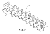
- Figure 2 shows a rotor 30 which in an embodiment may be mounted in the mixing chamber 22 of figure 1 and be driven by a motor 20 through transmission 21.
- the rotor 30 has a spiral 31 which pushes the dry homogeneous mixture from the inlet into the actual mixing chamber.
- the part of the rotor which is located in the actual mixing chamber is equipped with mixing blades 32.
- the rotor is suspended by axis 33.
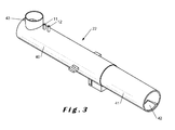
- Figure 3 shows how the mixing chamber 22 in an embodiment comprises a metal body 40, into which a plastic tube 41 is pushed.
- an opening 42 is provided to come above the outlet cover of the mixing machine, and also another opening (not shown) which is provided to come under the inlet for the dry homogeneous mixture.
- the lining 41 when it is brought in its place inside the body 40, is preferably anchored for example by putting a bolt through lining and body, at a suitable position such as position 43 indicated on figure 3 . After the lining is anchored, preferably then only an opening is drilled in the lining for the passage of the liquid ingredients through inlets 11 and 12 (indicated on figures 1 and 4 ).
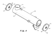
- Figure 4 shows how the mixing chamber according to the present invention, after the insertion of the internal lining, may be sealed.
- the body 40 may at each of both ends be closed with one cover 45 and 50.
- These covers are equipped with roller bearings 46 and 51 to support the rotor inside the mixing chamber. These roller bearings are of the closed type, to prevent disturbing matter from inside the mixing chamber from entering and disabling the roller bearing.
- the covers are preferably equipped with eyes 47, 48 and 52, 53, through which two threaded rods may be applied (not shown) and, by tightening of the nuts on these threaded rods, the covers may be pulled onto the body of the mixing chamber.
- Figure 4 also shows the inlets 10, 11 and 12, and the outlet cover 23, all discussed before as part of figure 1 . Outlet cover 23 is preferably also lined with a lining with the same characteristics as the lining of the mixing chamber.
Landscapes
- Chemical & Material Sciences (AREA)
- Chemical Kinetics & Catalysis (AREA)
- Engineering & Computer Science (AREA)
- Mechanical Engineering (AREA)
- Organic Chemistry (AREA)
- Processing And Handling Of Plastics And Other Materials For Molding In General (AREA)
Applications Claiming Priority (1)
| Application Number | Priority Date | Filing Date | Title |
|---|---|---|---|
| BE2012/0004A BE1020148A5 (nl) | 2012-01-02 | 2012-01-02 | Mengmachine voor de verwerking van composietmateriaal. |
Publications (1)
| Publication Number | Publication Date |
|---|---|
| EP2610040A1 true EP2610040A1 (de) | 2013-07-03 |
Family
ID=47427270
Family Applications (1)
| Application Number | Title | Priority Date | Filing Date |
|---|---|---|---|
| EP13150053.0A Withdrawn EP2610040A1 (de) | 2012-01-02 | 2013-01-02 | Mischvorrichtung und -verfahren für die Herstellung von Verbundstoffmaterial |
Country Status (2)
| Country | Link |
|---|---|
| EP (1) | EP2610040A1 (de) |
| BE (1) | BE1020148A5 (de) |
Cited By (17)
| Publication number | Priority date | Publication date | Assignee | Title |
|---|---|---|---|---|
| CN103978571A (zh) * | 2014-05-30 | 2014-08-13 | 昆山恩源塑料科技有限公司 | 一种塑料搅拌机装置 |
| CN103978570A (zh) * | 2014-05-30 | 2014-08-13 | 昆山恩源塑料科技有限公司 | 一种带弧形翼的塑料搅拌机装置 |
| CN103978569A (zh) * | 2014-05-30 | 2014-08-13 | 昆山恩源塑料科技有限公司 | 一种双轴驱动的塑料搅拌机装置 |
| CN104175411A (zh) * | 2014-07-18 | 2014-12-03 | 宋旭 | 自动吸料、除湿、除尘式高速混合机 |
| CN106426600A (zh) * | 2016-11-24 | 2017-02-22 | 无锡同心塑料制品有限公司 | 一种精细化工塑料助剂调配设备 |
| CN106626123A (zh) * | 2016-12-07 | 2017-05-10 | 安徽利得隆包装有限公司 | 一种出口用食品包装pet吸塑盒原料混合机 |
| CN106626124A (zh) * | 2016-12-07 | 2017-05-10 | 安徽利得隆包装有限公司 | 一种出口用食品包装pvc吸塑盒原料混匀设备 |
| RU2647305C1 (ru) * | 2016-06-22 | 2018-03-15 | Сергей Вячеславович Меркулов | Линия по производству изделий из композитного материала |
| CN111186984A (zh) * | 2020-02-28 | 2020-05-22 | 福州新福兴浮法玻璃有限公司 | 一种特大型玻璃配合料混合机 |
| CN112440401A (zh) * | 2020-10-30 | 2021-03-05 | 江苏淼泓环保新材料科技有限公司 | 一种聚氨酯混合搅拌机构 |
| CN112454710A (zh) * | 2020-11-28 | 2021-03-09 | 杭州雷力信息科技有限公司 | 一种基于绿色环保的橡胶密炼加工设备 |
| CN113146873A (zh) * | 2021-04-14 | 2021-07-23 | 张丽娜 | 一种阻燃型不饱和聚酯树脂复合材料的加工设备 |
| CN114130347A (zh) * | 2022-02-07 | 2022-03-04 | 烟台道成化学有限公司 | 一种用于水性聚氨酯树脂的恒粘度滴加装置 |
| CN115648470A (zh) * | 2022-12-12 | 2023-01-31 | 河北双羊砂轮制造有限公司 | 一种树脂砂轮加工的高混合均匀度的混料机及其方法 |
| CN116021744A (zh) * | 2022-12-15 | 2023-04-28 | 连云港联润新材料有限公司 | 一种环保型金色环氧模塑封料生产装置及其方法 |
| CN116809431A (zh) * | 2023-08-31 | 2023-09-29 | 江苏欧港昌盛装饰材料有限公司 | 一种可缺陷检测的地板生产线用运输系统 |
| CN118024435A (zh) * | 2023-12-26 | 2024-05-14 | 浙江高凯新材料有限公司 | 一种一次性环保塑料杯原料混合设备及其方法 |
Families Citing this family (2)
| Publication number | Priority date | Publication date | Assignee | Title |
|---|---|---|---|---|
| CN112454707B (zh) * | 2020-09-23 | 2022-03-18 | 宁波前鸿自动化科技有限公司 | 带有自收纳功能的塑料颗粒搅拌机 |
| CN119858253B (zh) * | 2025-02-21 | 2025-12-12 | 湖南协成管业科技有限公司 | 一种竹塑复合材料制造装置及其方法 |
Citations (12)
| Publication number | Priority date | Publication date | Assignee | Title |
|---|---|---|---|---|
| GB1354299A (en) * | 1971-05-03 | 1974-06-05 | Portec Inc | Railway sleepers |
| US4205919A (en) | 1975-08-20 | 1980-06-03 | London Brick Buildings Limited | Mixer for and method for mixing particulate constituents |
| US4223996A (en) * | 1977-03-09 | 1980-09-23 | Mathis Fertigputz Gmbh | Apparatus for mixing solid and liquid constituents of mortar or the like |
| US4785967A (en) * | 1985-02-06 | 1988-11-22 | Draiswerke Gmbh | Liner for a mixer container |
| EP0307562A2 (de) | 1987-09-12 | 1989-03-22 | Klöckner Ferromatik Desma GmbH | Vorrichtung zum Mischen von Isocyanat und Polyol, deren Gemisch zu Polyurethan ausreagiert |
| US4899912A (en) | 1986-08-27 | 1990-02-13 | Klockner Ferromatik Desma Gmbh | Device for preparing and ejecting a chemically reacting mixture |
| DE19908732A1 (de) | 1999-03-01 | 2000-09-07 | Pft Gmbh | Mischrohrvorrichtung eines horizontalen Durchlaufmischers für Mörtel |
| DE10311342B3 (de) | 2003-03-14 | 2004-08-26 | Mai International Gmbh | Mörtelmischpumpe |
| DE10351300A1 (de) * | 2003-10-31 | 2005-05-25 | Mikoleizig, Egenhardt, Dipl.-Ing. (FH) | Regelklappe |
| AT11535U1 (de) * | 2009-09-22 | 2010-12-15 | Gmundner Fertigteile Gmbh | Lasttragfähige platten- oder balkenförmige formkörper für den gleisbau |
| WO2011007322A2 (en) | 2009-07-15 | 2011-01-20 | Ludo Debergh | Method for producing a shaped object of a composite material, a shaped object produced according to this method |
| US20110061751A1 (en) * | 2009-09-15 | 2011-03-17 | Siam Cast Iron Works Co., Ltd. | Tilting Disc Swing Check Valve |
Family Cites Families (1)
| Publication number | Priority date | Publication date | Assignee | Title |
|---|---|---|---|---|
| US5727878A (en) * | 1996-10-17 | 1998-03-17 | Cdf Corporation | Liner for a mixing container and an assembly and method for mixing fluid components |
-
2012
- 2012-01-02 BE BE2012/0004A patent/BE1020148A5/nl active
-
2013
- 2013-01-02 EP EP13150053.0A patent/EP2610040A1/de not_active Withdrawn
Patent Citations (12)
| Publication number | Priority date | Publication date | Assignee | Title |
|---|---|---|---|---|
| GB1354299A (en) * | 1971-05-03 | 1974-06-05 | Portec Inc | Railway sleepers |
| US4205919A (en) | 1975-08-20 | 1980-06-03 | London Brick Buildings Limited | Mixer for and method for mixing particulate constituents |
| US4223996A (en) * | 1977-03-09 | 1980-09-23 | Mathis Fertigputz Gmbh | Apparatus for mixing solid and liquid constituents of mortar or the like |
| US4785967A (en) * | 1985-02-06 | 1988-11-22 | Draiswerke Gmbh | Liner for a mixer container |
| US4899912A (en) | 1986-08-27 | 1990-02-13 | Klockner Ferromatik Desma Gmbh | Device for preparing and ejecting a chemically reacting mixture |
| EP0307562A2 (de) | 1987-09-12 | 1989-03-22 | Klöckner Ferromatik Desma GmbH | Vorrichtung zum Mischen von Isocyanat und Polyol, deren Gemisch zu Polyurethan ausreagiert |
| DE19908732A1 (de) | 1999-03-01 | 2000-09-07 | Pft Gmbh | Mischrohrvorrichtung eines horizontalen Durchlaufmischers für Mörtel |
| DE10311342B3 (de) | 2003-03-14 | 2004-08-26 | Mai International Gmbh | Mörtelmischpumpe |
| DE10351300A1 (de) * | 2003-10-31 | 2005-05-25 | Mikoleizig, Egenhardt, Dipl.-Ing. (FH) | Regelklappe |
| WO2011007322A2 (en) | 2009-07-15 | 2011-01-20 | Ludo Debergh | Method for producing a shaped object of a composite material, a shaped object produced according to this method |
| US20110061751A1 (en) * | 2009-09-15 | 2011-03-17 | Siam Cast Iron Works Co., Ltd. | Tilting Disc Swing Check Valve |
| AT11535U1 (de) * | 2009-09-22 | 2010-12-15 | Gmundner Fertigteile Gmbh | Lasttragfähige platten- oder balkenförmige formkörper für den gleisbau |
Cited By (25)
| Publication number | Priority date | Publication date | Assignee | Title |
|---|---|---|---|---|
| CN103978570A (zh) * | 2014-05-30 | 2014-08-13 | 昆山恩源塑料科技有限公司 | 一种带弧形翼的塑料搅拌机装置 |
| CN103978569A (zh) * | 2014-05-30 | 2014-08-13 | 昆山恩源塑料科技有限公司 | 一种双轴驱动的塑料搅拌机装置 |
| CN103978571A (zh) * | 2014-05-30 | 2014-08-13 | 昆山恩源塑料科技有限公司 | 一种塑料搅拌机装置 |
| CN104175411A (zh) * | 2014-07-18 | 2014-12-03 | 宋旭 | 自动吸料、除湿、除尘式高速混合机 |
| RU2647305C1 (ru) * | 2016-06-22 | 2018-03-15 | Сергей Вячеславович Меркулов | Линия по производству изделий из композитного материала |
| CN106426600A (zh) * | 2016-11-24 | 2017-02-22 | 无锡同心塑料制品有限公司 | 一种精细化工塑料助剂调配设备 |
| CN106626124A (zh) * | 2016-12-07 | 2017-05-10 | 安徽利得隆包装有限公司 | 一种出口用食品包装pvc吸塑盒原料混匀设备 |
| CN106626124B (zh) * | 2016-12-07 | 2019-04-23 | 江苏古柏包装科技有限公司 | 一种出口用食品包装pvc吸塑盒原料混匀设备 |
| CN106626123B (zh) * | 2016-12-07 | 2019-05-10 | 汕头市庆丰塑胶制品有限公司 | 一种出口用食品包装pet吸塑盒原料混合机 |
| CN106626123A (zh) * | 2016-12-07 | 2017-05-10 | 安徽利得隆包装有限公司 | 一种出口用食品包装pet吸塑盒原料混合机 |
| CN111186984B (zh) * | 2020-02-28 | 2022-10-21 | 福州新福兴玻璃科技有限公司 | 一种特大型玻璃配合料混合机 |
| CN111186984A (zh) * | 2020-02-28 | 2020-05-22 | 福州新福兴浮法玻璃有限公司 | 一种特大型玻璃配合料混合机 |
| CN112440401A (zh) * | 2020-10-30 | 2021-03-05 | 江苏淼泓环保新材料科技有限公司 | 一种聚氨酯混合搅拌机构 |
| CN112454710A (zh) * | 2020-11-28 | 2021-03-09 | 杭州雷力信息科技有限公司 | 一种基于绿色环保的橡胶密炼加工设备 |
| CN112454710B (zh) * | 2020-11-28 | 2022-06-10 | 深圳海源恒业高新材料科技研发有限公司 | 一种基于绿色环保的橡胶密炼加工设备 |
| CN113146873A (zh) * | 2021-04-14 | 2021-07-23 | 张丽娜 | 一种阻燃型不饱和聚酯树脂复合材料的加工设备 |
| CN113146873B (zh) * | 2021-04-14 | 2023-09-22 | 浙江宝贝故事实业有限公司 | 一种阻燃型不饱和聚酯树脂复合材料的加工设备 |
| CN114130347A (zh) * | 2022-02-07 | 2022-03-04 | 烟台道成化学有限公司 | 一种用于水性聚氨酯树脂的恒粘度滴加装置 |
| CN115648470A (zh) * | 2022-12-12 | 2023-01-31 | 河北双羊砂轮制造有限公司 | 一种树脂砂轮加工的高混合均匀度的混料机及其方法 |
| CN115648470B (zh) * | 2022-12-12 | 2023-04-14 | 河北双羊砂轮制造有限公司 | 一种树脂砂轮加工的混合均匀的混料机及其混料方法 |
| CN116021744A (zh) * | 2022-12-15 | 2023-04-28 | 连云港联润新材料有限公司 | 一种环保型金色环氧模塑封料生产装置及其方法 |
| CN116021744B (zh) * | 2022-12-15 | 2023-09-29 | 连云港联润新材料有限公司 | 一种环保型金色环氧模塑封料生产装置及其方法 |
| CN116809431A (zh) * | 2023-08-31 | 2023-09-29 | 江苏欧港昌盛装饰材料有限公司 | 一种可缺陷检测的地板生产线用运输系统 |
| CN116809431B (zh) * | 2023-08-31 | 2023-11-10 | 江苏欧港昌盛装饰材料有限公司 | 一种可缺陷检测的地板生产线用运输系统 |
| CN118024435A (zh) * | 2023-12-26 | 2024-05-14 | 浙江高凯新材料有限公司 | 一种一次性环保塑料杯原料混合设备及其方法 |
Also Published As
| Publication number | Publication date |
|---|---|
| BE1020148A5 (nl) | 2013-05-07 |
Similar Documents
| Publication | Publication Date | Title |
|---|---|---|
| BE1020148A5 (nl) | Mengmachine voor de verwerking van composietmateriaal. | |
| FI65765B (fi) | Anordning foer behandling av slam | |
| EP3023545A1 (de) | Fugensanierungsmaschine und verfahren zu deren betrieb | |
| EP3684576B1 (de) | Mischer und darauf bezogenes verfahren | |
| DE9208671U1 (de) | Vorrichtung zur Aufbereitung von Schmutzwasser mit Trenneinrichtung für Zuschlagstoffe | |
| EP2454062B1 (de) | Verfahren zur herstellung eines formobjekts aus einem verbundstoff und nach diesem verfahren hergestelltes formobjekt | |
| EP3137220B1 (de) | Hydrodynamische schwerstoffabtrennung einer aufschlämmung | |
| EP3725411A1 (de) | Vorrichtung zum entfernen einer anhaftenden substanz aus partikulärem material oder zum zerkleinern von material | |
| US10634274B2 (en) | Pipe transporter traction wheel | |
| Guyer et al. | An introduction to sludge handling, treatment and disposal | |
| KR100467295B1 (ko) | 원심력을 이용한 수지 콘크리트관의 제조방법 및 그제조장치 | |
| JP2023009253A (ja) | 固液分離設備 | |
| WO2020030729A1 (de) | Verfahren und system zur aufbereitung von betonrestwasser | |
| US20180208100A1 (en) | Pipe Transporter Traction Wheel | |
| KR100651232B1 (ko) | 파분쇄 건설폐기물을 이용한 고강도 순환골재 제조장치 및방법 | |
| DE102013112564B4 (de) | Verfahren und Vorrichtungen zur Sanierung von Rissen in Asphaltflächen oder ähnlich gearteten Flächen | |
| CN212271626U (zh) | 一种混凝土垂直输送泵管尾料回收再利用装置 | |
| CN110340125B (zh) | 一种重金属污染土壤修复方法 | |
| CN107900077A (zh) | 一种城市垃圾处理系统 | |
| KR200260606Y1 (ko) | 원심력을 이용한 수지 콘크리트관의 제조장치 | |
| CN206495209U (zh) | 一种喷浆设备 | |
| KR20130097943A (ko) | 폴리우레탄계 콘크리트구조물 방식용 수지조성물을 이용한 내면 라이닝 원심력 철근콘크리트관의 제조방법 | |
| CN212576840U (zh) | 一种砂石筛分机 | |
| CN219482955U (zh) | 一种集料预处理装置 | |
| DE102014015213A1 (de) | Herstellung von Dehnungsfugen in befestigten Innenflächen und Außenflächen |
Legal Events
| Date | Code | Title | Description |
|---|---|---|---|
| PUAI | Public reference made under article 153(3) epc to a published international application that has entered the european phase |
Free format text: ORIGINAL CODE: 0009012 |
|
| AK | Designated contracting states |
Kind code of ref document: A1 Designated state(s): AL AT BE BG CH CY CZ DE DK EE ES FI FR GB GR HR HU IE IS IT LI LT LU LV MC MK MT NL NO PL PT RO RS SE SI SK SM TR |
|
| AX | Request for extension of the european patent |
Extension state: BA ME |
|
| 17P | Request for examination filed |
Effective date: 20131231 |
|
| RBV | Designated contracting states (corrected) |
Designated state(s): AL AT BE BG CH CY CZ DE DK EE ES FI FR GB GR HR HU IE IS IT LI LT LU LV MC MK MT NL NO PL PT RO RS SE SI SK SM TR |
|
| 17Q | First examination report despatched |
Effective date: 20141107 |
|
| STAA | Information on the status of an ep patent application or granted ep patent |
Free format text: STATUS: THE APPLICATION IS DEEMED TO BE WITHDRAWN |
|
| 18D | Application deemed to be withdrawn |
Effective date: 20150519 |