EP2610048B1 - Schäumvorrichtung zur Herstellung von Dämmplatten - Google Patents
Schäumvorrichtung zur Herstellung von Dämmplatten Download PDFInfo
- Publication number
- EP2610048B1 EP2610048B1 EP12189957.9A EP12189957A EP2610048B1 EP 2610048 B1 EP2610048 B1 EP 2610048B1 EP 12189957 A EP12189957 A EP 12189957A EP 2610048 B1 EP2610048 B1 EP 2610048B1
- Authority
- EP
- European Patent Office
- Prior art keywords
- mold
- mold plate
- foaming
- pivoting
- plate
- Prior art date
- Legal status (The legal status is an assumption and is not a legal conclusion. Google has not performed a legal analysis and makes no representation as to the accuracy of the status listed.)
- Active
Links
- 238000009413 insulation Methods 0.000 title claims description 96
- 238000005187 foaming Methods 0.000 title claims description 52
- 230000000295 complement effect Effects 0.000 claims description 3
- 238000003860 storage Methods 0.000 claims description 2
- 238000012546 transfer Methods 0.000 claims description 2
- 230000004913 activation Effects 0.000 claims 1
- 230000007306 turnover Effects 0.000 claims 1
- 239000006260 foam Substances 0.000 description 18
- 238000004519 manufacturing process Methods 0.000 description 15
- 238000000034 method Methods 0.000 description 10
- 238000005520 cutting process Methods 0.000 description 7
- 238000013461 design Methods 0.000 description 7
- 239000000463 material Substances 0.000 description 5
- 230000015572 biosynthetic process Effects 0.000 description 3
- 238000001514 detection method Methods 0.000 description 3
- 238000009434 installation Methods 0.000 description 3
- 238000000465 moulding Methods 0.000 description 2
- 239000011505 plaster Substances 0.000 description 2
- 239000004033 plastic Substances 0.000 description 2
- 238000003825 pressing Methods 0.000 description 2
- 239000002699 waste material Substances 0.000 description 2
- 239000000853 adhesive Substances 0.000 description 1
- 230000001070 adhesive effect Effects 0.000 description 1
- 230000002411 adverse Effects 0.000 description 1
- 230000033228 biological regulation Effects 0.000 description 1
- 230000008878 coupling Effects 0.000 description 1
- 238000010168 coupling process Methods 0.000 description 1
- 238000005859 coupling reaction Methods 0.000 description 1
- 230000007423 decrease Effects 0.000 description 1
- 230000001419 dependent effect Effects 0.000 description 1
- 230000008030 elimination Effects 0.000 description 1
- 238000003379 elimination reaction Methods 0.000 description 1
- 238000011156 evaluation Methods 0.000 description 1
- 239000004794 expanded polystyrene Substances 0.000 description 1
- 239000012634 fragment Substances 0.000 description 1
- 239000003292 glue Substances 0.000 description 1
- 238000007654 immersion Methods 0.000 description 1
- 239000011810 insulating material Substances 0.000 description 1
- 238000012545 processing Methods 0.000 description 1
- 230000001105 regulatory effect Effects 0.000 description 1
- 238000009966 trimming Methods 0.000 description 1
Images




Classifications
-
- B—PERFORMING OPERATIONS; TRANSPORTING
- B29—WORKING OF PLASTICS; WORKING OF SUBSTANCES IN A PLASTIC STATE IN GENERAL
- B29C—SHAPING OR JOINING OF PLASTICS; SHAPING OF MATERIAL IN A PLASTIC STATE, NOT OTHERWISE PROVIDED FOR; AFTER-TREATMENT OF THE SHAPED PRODUCTS, e.g. REPAIRING
- B29C44/00—Shaping by internal pressure generated in the material, e.g. swelling or foaming ; Producing porous or cellular expanded plastics articles
- B29C44/34—Auxiliary operations
- B29C44/58—Moulds
- B29C44/585—Moulds with adjustable size of the mould cavity
-
- B—PERFORMING OPERATIONS; TRANSPORTING
- B29—WORKING OF PLASTICS; WORKING OF SUBSTANCES IN A PLASTIC STATE IN GENERAL
- B29C—SHAPING OR JOINING OF PLASTICS; SHAPING OF MATERIAL IN A PLASTIC STATE, NOT OTHERWISE PROVIDED FOR; AFTER-TREATMENT OF THE SHAPED PRODUCTS, e.g. REPAIRING
- B29C33/00—Moulds or cores; Details thereof or accessories therefor
- B29C33/30—Mounting, exchanging or centering
- B29C33/308—Adjustable moulds
-
- B—PERFORMING OPERATIONS; TRANSPORTING
- B30—PRESSES
- B30B—PRESSES IN GENERAL
- B30B15/00—Details of, or accessories for, presses; Auxiliary measures in connection with pressing
- B30B15/06—Platens or press rams
- B30B15/068—Drive connections, e.g. pivotal
-
- E—FIXED CONSTRUCTIONS
- E04—BUILDING
- E04D—ROOF COVERINGS; SKY-LIGHTS; GUTTERS; ROOF-WORKING TOOLS
- E04D13/00—Special arrangements or devices in connection with roof coverings; Protection against birds; Roof drainage ; Sky-lights
- E04D13/16—Insulating devices or arrangements in so far as the roof covering is concerned, e.g. characterised by the material or composition of the roof insulating material or its integration in the roof structure
- E04D13/1687—Insulating devices or arrangements in so far as the roof covering is concerned, e.g. characterised by the material or composition of the roof insulating material or its integration in the roof structure the insulating material having provisions for roof drainage
- E04D13/1693—Insulating devices or arrangements in so far as the roof covering is concerned, e.g. characterised by the material or composition of the roof insulating material or its integration in the roof structure the insulating material having provisions for roof drainage the upper surface of the insulating material forming an inclined surface
Definitions
- the invention relates to a device for the production of foamed insulation boards with a foaming mold surrounded by mold boards and mold frames according to the preamble of claim 1.
- JP 62 208 912 A discloses a device for producing foamed bodies.
- the DE 88 074 66 U1 relates to one made of an insulating material such as
- U1 is a tool according to the preamble of claim 1 for the production of molded parts with at least one flexible mold wall delimiting a mold space.
- This device comprises adjustably mounted walls which are each fastened to an elastically deformable support frame.
- the carrier frames are, for example, mounted on six adjustment devices designed as hydraulic lifting cylinders. In this way, it should be possible to set the adjustably mounted walls at an angle and / or to curve them with respect to the stationary frame walls delimiting the mold space.
- Foaming devices for the production of insulation boards are known in many ways from the prior art. Depending on the application and the embodiment of insulation boards, these are produced in a single process, especially in the case of facade insulation boards. In the event that insulation panels are required which have a wedge-shaped structure, such an execution method from the prior art fails. In this regard, it is known to produce, in particular, sloping roof tiles from a large block by means of cutting.
- a foamed insulation block is first produced in a known manner, which has the main dimensions of the insulation board to be produced. To achieve the wedge-shaped shape, the foamed block is cut through at an inclined angle over the entire surface of the dam plate.
- the object of the present invention is therefore to provide a device for the production of insulation boards by means of which wedge-shaped insulation boards are made available more cost-effectively and with better quality than in the case of wedge-shaped insulation boards produced previously.
- the object set is achieved by a device according to the invention according to claim 1.
- the generic device is initially intended for the production of foamed insulation boards. Although it would theoretically be conceivable to use the device to produce a larger block in order to then subdivide it into slices or pieces to form a plurality of insulation panels, it can generally be assumed that each individual insulation panel is used in a production process will be produced. These insulation panels produced are used in particular as roof slope panels in building insulation.
- the foam mold in the device represents a type of cavity within which the insulation board is manufactured.
- the foam mold is defined by two opposing mold plates and a surrounding mold frame.
- One of the mold plates here forms a base, the correspondingly opposite mold plate forming a cover.
- a free distance is created between the mold plates, which consequently defines the thickness of the foaming mold or the thickness of the insulation boards to be produced.
- the surrounding area is the space between the two mold plates, i.e. the foam mold, enclosed by a mold frame, it is initially irrelevant whether this mold frame also encloses the mold plates or one of the mold plates or just bridges the distance between the two mold plates.
- At least a corresponding, essentially closed foam mold is formed by the mold plates and the mold frame.
- cover mold plate is immersed in the mold frame or rests on it, it is irrelevant for the generic design if the mold frame is made in several parts and here a cover-side section of the mold frame is firmly connected to the cover mold plate or the cover mold plate integrally comprises a section of the mold frame. This consideration is neglected below, but can easily be added as an alternative for the person skilled in the art. At least provision is made for the insulation board to be removable or ejectable on this side when the cover molded plate with or without a section of the molded frame is removed. In this sense, the term “cover mold plate” in the following also includes a section of the mold frame on the cover side, if so designed.
- the bottom mold plate is generally not removable from the mold frame in such a way that it would also be possible to remove the insulation board on this side.
- the swivel device has at least one swivel drive, by means of which at least one of the mold plates can be adjusted in its angular arrangement to the opposite mold plate.
- This newly created embodiment of a foaming device using a swivel device makes it possible for the first time to produce wedge-shaped insulation panels directly in the foaming mold without the need for a subsequent cutting of a larger foamed block.
- the negative influence on the surface of the insulation board is especially advantageously eliminated.
- the newly enabled manufacturing process also eliminates the otherwise usual waste residue when cutting a block.
- the bottom mold plate or, alternatively, the lid mold plate or even both mold plates are changed in their angular position by means of the swivel device.
- the only decisive factor is that the angular arrangement of the top mold plate can be changed relative to the bottom mold plate in such a way that a wedge-shaped foam mold is formed.
- the swivel device has at least two swivel bearings arranged on the swiveling mold plate. This requires the arrangement of a pivot drive on at least one pivot bearing.
- the swivel drive is used in connection with the one swivel bearing, which is accompanied by swiveling of the mold plate about the other swivel bearing.
- the type of swivel mounting is initially irrelevant. It is only essential that the process-related forces can be transferred. In this respect, it is also irrelevant whether the swivel mounting is a hinge, a ball bearing or some other type of mounting.
- the pivoting device and the pivotable mold plate are designed in such a way that at least an angle change of 1 °, particularly preferably of at least 2 °, is made possible.
- the pivot angle ie the change in angle
- the pivotable mold plate is arranged within the mold frame.
- the change in the angular arrangement between the mold plates inevitably changes the distance between the two mold plates on the circumferential edge.
- a changing length of the mold frame is required for the circumferential closure of the foam mold. This is achieved in a particularly simple manner if the mold frame also encloses the pivotable mold plate. It is also particularly advantageous here if the pivotable mold plate forms the bottom mold plate and the lid mold plate forms the opposing mold plate.
- the pivotable mold plate and the opposing mold plate that a wedge-shaped insulating panel is formed.
- the surface for the foaming mold of at least one mold plate is inclined to the opposite mold plate.
- the Angular arrangement selected between the mold plates in the starting position taking into account the possible change in angle by the pivoting device. For example, if the possible change in angle between the molded panels is ⁇ 1.5 ° from the initial position, a wedge angle between 1 ° and 4 ° can be achieved for the insulation panels by selecting the angle arrangement in the initial position of 2.5 °.
- Which of the two mold plates has an inclined arrangement in the starting position is initially irrelevant. It is possible to choose an inclined design for both mold plates. It is also possible to select the mold plate opposite the pivotable mold plate as the mold plate inclined in the starting position, the pivotable mold plate being oriented at right angles to the mold frame in the starting position.
- the mold plate opposite the pivotable mold plate is arranged at right angles to the mold frame and the pivotable mold plate already has an angular arrangement with respect to the opposite mold plate in the starting position. I.e. the pivotable mold plate is not arranged parallel to the opposite mold plate. This is due in particular to the later use and installation of the insulation boards, with the particularly preferred shape of the insulation boards with a right-angled arrangement of a surface of the insulation boards to the circumferential edge of the insulation board, a virtually joint-free and gap-free installation of the insulation boards is possible.
- a mold plate is arranged in the device so that it can be dismantled or replaced.
- the interchangeability has the particular advantage that with a limited adjustability of the swivel angle by means of the swivel device of, for example, ⁇ 1.5 °, any desired angle range can be selected by exchanging a mold plate.
- Another mold plate that can be exchanged for this purpose has, for example, the angular offset of 4.5 ° and in turn another the angular offset of 7.5 °.
- the pivotable mold plate is interchangeably connected to the pivoting device.
- the pivot bearing can be directly the coupling means for fastening the mold plate to the pivoting device, and alternatively the pivotable mold plate can also be connected to the pivot bearing by means of connecting means.
- the swivel device has at least three swivel bearings and at least two swivel drives engaging two swivel bearings.
- the use of three spatially offset swivel bearings with the use of two swivel drives enables the swiveling mold plate to be adjusted spatially.
- the pivotable mold plate be adjusted in such a way that a wedge-shaped shape is created along only one side edge of the foam mold or the insulation board to be produced, but rather wedge angles can be formed diagonally across the insulation board to be produced, i.e. all sides of the foam mold or the insulation board to be produced have a wedge shape.
- the swivel device has a swivel drive for each swivel bearing.
- movements of the swivel drives in opposite directions in particular can be implemented and the mean distance between the pivotable mold plate relative to the opposite mold plate is not influenced by pivoting the pivotable mold plate by using the pivot drives, although this is also possible.
- the swivel device has at least four swivel bearings, in particular ball bearings, which are arranged in a distributed manner and which are each connected to a swivel drive. This enables a secure connection of the pivotable mold plate and at the same time a spatial adjustment with regard to the angular arrangement between the opposing mold plates.
- the swivel drive has a spindle motor with a threaded spindle as the adjusting means.
- a precise setting of the swivel angle of the swiveling mold plate can be achieved by means of a defined retraction and extension of the adjusting means with engagement on the pivot bearing.
- the spindle motor is particularly suitable in that a precise setting is ensured when high forces are transmitted, with a low speed of the spindle motor not being important.
- the device furthermore has an adjusting device.
- the adjusting device comprises at least one adjusting drive, by means of which a nominal distance between the two mold plates can be adjusted.
- the nominal distance refers to the distance between the bottom mold plate and the lid mold plate that is present without taking the pivoting device into account.
- the bottom mold plate or the lid mold plate or, alternatively, both mold plates are adjustable by means of an adjusting device.
- one of the two mold plates means of the adjustment drive is adjustable and at the same time moves relative to the mold frame. It is at least decisive that, by adjusting a shaped plate while changing the nominal distance, corresponding insulation boards with different material thicknesses can be formed.
- Various embodiments are available for realizing the corresponding adjusting drive, in particular the embodiment with a spindle motor as adjusting drive can preferably be used, wherein a threaded spindle of the spindle motor can be retracted and extended.
- a slow movement is sufficient, while a precise setting of the nominal distance is preferred.
- the spindle drive makes this particularly advantageous.
- the adjustability of the pivotable mold plate is ensured within the intended adjustment range.
- the pivotable mold plate is guided over other guides in such a way that the mold plate does not come into contact with the mold frame.
- column guides can be provided between the pivoting device behind the mold plate and an attachment part of the mold frame.
- the mold frame can advantageously be lengthened and a non-pivoting part of the pivoting device can be supported in the mold frame by means of a bearing arrangement.
- the pivotable mold plate is advantageously provided with a sliding seal, which in this case has such an elasticity that changes in the width of the gap between the pivotable mold plate and the mold frame are irrelevant to the effectiveness of the sliding seal.
- the adjusting drive is arranged in such a way that it is functionally in a row with the pivoting drive. This means that when the pivotable mold plate is adjusted by means of the adjustment drive, the pivot drive of the pivoting device is moved at the same time. This is done, for example, in that the adjusting drive initially moves the entire swivel drive, to which the swiveling mold plate is in turn connected. Due to the task of the swivel drive with the associated change in angle, the use of the adjustment drive is more advantageous than with the reverse arrangement with an adjustment drive between the swivel drive and the swiveling mold plate.
- the pivotable mold plate is preferably arranged inside the mold frame, that is, the mold frame also surrounds the pivotable mold plate in addition to the foam mold.
- the pivotable mold plate is adjustable within the mold frame, while the other mold plate only needs to form the end of the mold frame.
- fixed does not necessarily mean that this is the bottom mold plate.
- the molded cover plate advantageously forms the correspondingly upright molded plate, which in this respect can be removed from the foam mold in order to remove the insulating plate.
- the insulation board is provided with a stepped shoulder can be.
- a stepped shoulder is advantageously required on the mold frame or on the bottom mold plate on one side or on two adjacent sides of the foam mold.
- the lid mold plate has a complementary stepped shoulder on the opposite side or the opposite sides of the foam mold. This particularly favors the later use of the insulation boards to join them without creating a continuous gap between the individual insulation boards.
- the height of the step shoulder can be changed, that is to say in the direction of the distance considered between the two mold plates. This is particularly true when considering the use of an adjustment device to change the nominal distance.
- the foamed insulation panels for building insulation if at least one of the two mold panels has a raised and / or recessed structure on the side facing the foam mold.
- a complementary structure is reproduced in the insulation boards produced. The design of the structure is initially irrelevant, although this can be based on the required use.
- the structure is designed in such a way that a surface with significantly increased roughness is created in the insulation board produced.
- the formed surface of the insulation board is at least twice as large as the area resulting from the dimensions of the molded board.
- a significantly better adhesion of both glue and plaster or the like to the corresponding insulation board is guaranteed due to the contact area being more than twice as large.
- a true-to-scale, in particular recessed, line grid is advantageously mapped on the surface of the insulation board on at least one side.
- the associated mold plate requires a raised line structure.
- the true-to-scale execution of the line grid facilitates the quick and uncomplicated assembly of an insulation board for connection to corresponding fragments of insulation boards, for example at the end of a building area to be insulated.
- one surface of the insulation board can be designed for applying an adhesive, the other side of the insulation board being optimized for applying plaster.
- the invention provides a new insulation board for building insulation.
- This first of all has the generic structure made of a foamed plastic material, in particular made of expanded polystyrene.
- the insulation board is rectangular when viewed in the plane of the board and has a wedge-shaped shape in cross section.
- the angular offset between the underside and the opposite top side of the insulation board is in a range between 1 ° and 10 °.
- the generic insulation panel can be used as a sloping roof panel.
- a characteristic feature of the insulation board according to the invention is now that it is shaped like a tool. This means that all surfaces of the insulation board are formed by foaming in a foam mold. The trimming of a surface of the insulation board, which is inevitably present in the prior art, is not present, however. This means that there are even surfaces on the insulation board on both the top and the bottom. In this regard, it is irrelevant whether, due to the structure of the foaming tool, different structuring or line patterns or the like are specifically incorporated. What is decisive is that the saw cut or glow wire cut customary in the prior art is now completely eliminated.
- the production of the insulation board is correspondingly advantageous if this is carried out by means of an embodiment of a foaming device described above. Furthermore, it is advantageous if the top and / or bottom has a surface structure with increased roughness or a line pattern. Thus, regardless of the tool, the use of the insulation board and the material to be connected can be taken into account or advantageous true-to-scale line patterns can be incorporated.
- the foaming device according to the invention leads to a foaming system according to the invention.
- An embodiment of the above-described foaming device is here supplemented by an input device for recording the building surfaces to be insulated to form the foaming system.
- a data transfer device can also be provided in order, for example, to be able to record the necessary building surface to be insulated directly from CAD models of the building.
- the foaming system has a calculation device for calculating the required insulation boards. Here, a comparison is made between the recorded building surfaces with the options for producing individual insulation panels in the foaming mold of the foaming device.
- the foaming system has an interrogation device and / or a setting memory device for recording the actual setting of the foaming device.
- the setting values are thus available for evaluation or the current state of the foaming mold in terms of dimensions and angular arrangement is known in the control of the foaming system.
- the Determination of the required target settings of the foaming device are carried out.
- the target settings of the foaming devices are determined from the previously calculated required insulation panels for building insulation.
- the required dimensions and the angular arrangement of the foaming mold are derived from this. This is associated with corresponding target settings of the foaming device.
- a comparison between the target settings and the actual settings now takes place by means of the calculation device or the control device.
- the control device activates at least one drive or a plurality of adjustment and / or swivel drives with an adjustment of the foaming device, so that in the following the foaming mold has the required geometry for producing the calculated Has insulation board. This ensures that the target settings match the actual settings.
- the newly created foaming system makes it possible, based on the detection of the building surface to be insulated, to produce a complete set of insulation panels, which can be used to insulate the building without further reworking. It is irrelevant here whether, due to the size of the insulation panels in the main dimensions, a cut in the edge area of the building surface to be insulated is unavoidable.
- the main advantage now is that the entire set of insulation panels can be manufactured in one process and thus the entire set is ready for use immediately after manufacture. It is therefore not necessary to assemble the required set of insulation boards from a large number of different insulation boards in terms of thickness and wedge shape.
- the foaming system has a Has turning device.
- the insulation boards produced can be removed from or taken over from the foam mold, with the insulation boards produced subsequently being able to be alternately placed on a stack in opposite orientations by means of the turning device. This means that in spite of the wedge shape, with two consecutive insulation panels each with the same wedge angle, a new upper parallel storage area is created on the two insulation panels and thus simplifies the transport of the insulation panels.
- a foaming system according to the invention is supplemented by a new method according to the invention, which is characterized by the sequence with detection of a building surface to be insulated in a wedge-shaped cross-section; the calculation of the required individual wedge-shaped insulation panels with, in particular, gradually increasing material thickness; the detection of the actual settings of the foaming device, in particular the set angular offset and a set distance between the lid mold plate and the bottom mold plate; the determination of the required target setting of the foaming device with a subsequent comparison of the actual setting with the target settings, with a deviation above a specified tolerance an adjustment of the top and / or bottom mold plate with adjustment of a distance and / or a Angular offset between the lid mold plate to the bottom mold plate takes place.
- the Figure 1 shows a foaming device 01 with a pivotable mold plate 05 and a fixed mold plate 06.
- the lid mold plate forms the fixed mold plate 06, the assignment to the mold frame 07 being invariable during the manufacturing process.
- the shaped cover plate 06 can be removed to remove the insulation board produced, for example by pivoting or lifting it off.
- the pivotable mold plate is formed by the bottom mold plate 05, which is located inside the mold frame 07 and can be adjusted at a distance 08 from the cover mold plate 06.
- the bottom molded plate 05 has an angular offset 14 relative to the lid molded plate 06 such that a wedge-shaped foam mold 02 is formed and thus wedge-shaped insulating panels can be produced.
- a pivoting device 11 is provided according to the invention.
- the swivel device 11 is formed by two spaced swivel drives 12 in the manner of spindle drives.
- the threaded spindle can be extended and retracted accordingly, whereby a corresponding adjustment of the pivotable mold plate 05 is associated.
- the distance 08 between the mold plates 05, 06 can be reduced or, in the opposite case, increased, both with simultaneous extension are, as well as with opposite adjustment or one-sided adjustment of the rotary drives 12.1, 12.2 a corresponding change in the angular offset 14 can be effected.
- the pivoting device 11 also forms an adjustment device for changing the nominal distance 08 between the two mold plates 05, 06.
- it is coupled to the respective pivot drives 12 via pivot bearings 13.
- the foaming device 01 is turned off again Fig. 1 Sketched, reducing to the consideration of the mold frame 07 and the pivotable mold plate or bottom mold plate 05.
- In the starting position results the gap 24 from the difference between the clear height 21 of the mold frame 07 and the height 22 of the mold plate 05 in the same measuring direction. Due to the exemplary inclined design of the pivotable mold plate 05, however, in the starting position it has a space length 23 that is greater than the height 22 of the mold plate 05.
- the pivotable mold plate 05 is now pivoted by means of the pivot drive 12 or the pivot drives 12.1, 12.2 with a change in the angular offset 14, this leads to a change in the gap 24. That is, depending on the pivoting direction, the gap 24 increases or decreases. In extreme cases, the gap close completely and thus inevitably limit the swivel angle when the spatial length 23 of the swiveling mold plate 05 is greater than the clear height 21 of the mold frame 07, which is generally to be assumed. In this respect, the usable pivot angle for changing the angular offset 14 is limited by the choice of the largest permissible gap in one pivot direction and the closing of the gap in the other pivot direction.
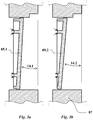
- FIG Figure 3 an exemplary solution in which the foaming device 01 is provided with two mold plates 05.1 and 05.2. These two mold plates 05.1 and 05.2 each have a different angular offset 14.1 and 14.2 in the starting position when they are attached to the pivoting device 11.
- the pivoting angle which is limited due to the gap formation, can thus be overcome in that the shaped plates 05.1 and 05.2 are alternately exchanged depending on the requirements of the angular arrangement 14 to be set or the angular range.
- FIG Figure 4a The angular adjustment of the pivotable mold plate provided according to the invention, in the example the bottom mold plate 05, and thus the change in the angular offset 14 is exemplified in FIG Figure 4 outlined.
- the Figure 4a the foaming device 01 in the starting position with the foaming mold 02 in a wedge shape corresponding to the angular offset 14a when the pivotable mold plate 05a is set in the starting position or the swivel drives 12a in the starting position. If the first pivoting drive 12.1b is now extended and the second pivoting drive 12.2b is retracted, this results in an increase in the angular offset 14b, as in FIG Figure 4b outlined. In contrast, when the first swivel drive 12.1c is retracted and the second swivel drive 12.2c is extended, the swivel angle 14c is reduced - see FIG Figure 4c .
- FIG Figure 5 another embodiment of a foaming device 31 is outlined, in which a pivoting device 41 coupled in series and an adjusting device 46 are present.
- the pivotable mold plate 35 can first of all be changed in its angular position by means of the pivot drive 41, for which purpose the pivotable mold plate 35 is mounted centrally and laterally by means of a individual swivel drive 42 can be adjusted.
- the pivoting device 41 has a pivoting support 45, which in turn can be adjusted by means of an adjusting drive 47, for example in the manner of a spindle drive, of the adjusting device 46 in such a way that this also results in a change in the distance to the other mold plate.
Landscapes
- Engineering & Computer Science (AREA)
- Mechanical Engineering (AREA)
- Architecture (AREA)
- Civil Engineering (AREA)
- Structural Engineering (AREA)
- Casting Or Compression Moulding Of Plastics Or The Like (AREA)
Applications Claiming Priority (1)
| Application Number | Priority Date | Filing Date | Title |
|---|---|---|---|
| DE202011109598U DE202011109598U1 (de) | 2011-12-29 | 2011-12-29 | Schäumvorrichtung zur Herstellung von Dämmplatten |
Publications (2)
| Publication Number | Publication Date |
|---|---|
| EP2610048A1 EP2610048A1 (de) | 2013-07-03 |
| EP2610048B1 true EP2610048B1 (de) | 2020-08-19 |
Family
ID=45832976
Family Applications (1)
| Application Number | Title | Priority Date | Filing Date |
|---|---|---|---|
| EP12189957.9A Active EP2610048B1 (de) | 2011-12-29 | 2012-10-25 | Schäumvorrichtung zur Herstellung von Dämmplatten |
Country Status (3)
| Country | Link |
|---|---|
| EP (1) | EP2610048B1 (pl) |
| DE (1) | DE202011109598U1 (pl) |
| PL (1) | PL2610048T3 (pl) |
Families Citing this family (12)
| Publication number | Priority date | Publication date | Assignee | Title |
|---|---|---|---|---|
| DE102013002519B4 (de) | 2013-02-13 | 2016-08-18 | Adidas Ag | Herstellungsverfahren für Dämpfungselemente für Sportbekleidung |
| DE102015202013B4 (de) | 2015-02-05 | 2019-05-09 | Adidas Ag | Verfahren zur Herstellung eines Kunststoffformteils, Kunststoffformteil und Schuh |
| DE102016209046B4 (de) | 2016-05-24 | 2019-08-08 | Adidas Ag | Verfahren zur herstellung einer schuhsohle, schuhsohle, schuh und vorgefertigte tpu-gegenstände |
| DE102016209044B4 (de) | 2016-05-24 | 2019-08-29 | Adidas Ag | Sohlenform zum Herstellen einer Sohle und Anordnung einer Vielzahl von Sohlenformen |
| DE102016209045B4 (de) | 2016-05-24 | 2022-05-25 | Adidas Ag | Verfahren und vorrichtung zum automatischen herstellen von schuhsohlen, sohlen und schuhe |
| DE102016223980B4 (de) | 2016-12-01 | 2022-09-22 | Adidas Ag | Verfahren zur Herstellung eines Kunststoffformteils |
| DE202017107149U1 (de) * | 2016-12-01 | 2018-03-05 | Kurtz Gmbh | Crackspalt-Formwerkzeug zum Herstellen eines Partikelschaumstoffteils sowie Vorrichtung zum Herstellen eines Partikelschaumstoffteils |
| DE102016123214A1 (de) | 2016-12-01 | 2018-06-07 | Kurtz Gmbh | Vorrichtung zur Herstellung eines Partikelschaumstoffteils |
| DE102017205830B4 (de) | 2017-04-05 | 2020-09-24 | Adidas Ag | Verfahren für die Nachbehandlung einer Vielzahl einzelner expandierter Partikel für die Herstellung mindestens eines Teils eines gegossenen Sportartikels, Sportartikel und Sportschuh |
| NL2019184B1 (nl) * | 2017-07-05 | 2019-01-16 | Isobouw Systems Bv | Inrichting en werkwijze voor het produceren van een plaatvormig geschuimd matrijs gevormd kunststof product. |
| DE202018102138U1 (de) | 2018-04-18 | 2019-07-19 | Kurtz Gmbh | Werkzeug und Vorrichtung zur Herstellung von geschäumten Dämmplatten |
| CN115923105A (zh) * | 2023-02-21 | 2023-04-07 | 杭州方圆塑机股份有限公司 | 一种板材机双挤压结构 |
Citations (2)
| Publication number | Priority date | Publication date | Assignee | Title |
|---|---|---|---|---|
| US20080168741A1 (en) * | 2007-01-11 | 2008-07-17 | The Mattamy Corporation | Wall fabrication system and method |
| EP2072208A2 (en) * | 2007-12-21 | 2009-06-24 | Kingspan Research and Developments Limited | Manufacture of insulating board |
Family Cites Families (6)
| Publication number | Priority date | Publication date | Assignee | Title |
|---|---|---|---|---|
| US3921515A (en) * | 1974-04-26 | 1975-11-25 | Gen Electric | Compactor |
| JPS62208912A (ja) * | 1986-03-10 | 1987-09-14 | Ig Tech Res Inc | 発泡体の製造装置 |
| DE8807466U1 (de) * | 1988-06-08 | 1988-08-18 | Iso Bouw B.V., Someren | Dachplatte |
| DE10259336A1 (de) * | 2002-12-18 | 2004-07-08 | Saint-Gobain Isover G+H Ag | Geformte Dämmplatte aus Mineralwolle |
| DE202004003679U1 (de) * | 2004-03-08 | 2004-05-13 | Kurtz Gmbh | Werkzeug zur Herstellung von Formteilen |
| DE102006059796A1 (de) * | 2006-12-15 | 2008-06-19 | Müller Weingarten AG | Verfahren und Vorrichtung zur Steuerung und Regelung von Stößellageabweichungen an servo-elektrischen Pressen |
-
2011
- 2011-12-29 DE DE202011109598U patent/DE202011109598U1/de not_active Expired - Lifetime
-
2012
- 2012-10-25 EP EP12189957.9A patent/EP2610048B1/de active Active
- 2012-10-25 PL PL12189957.9T patent/PL2610048T3/pl unknown
Patent Citations (2)
| Publication number | Priority date | Publication date | Assignee | Title |
|---|---|---|---|---|
| US20080168741A1 (en) * | 2007-01-11 | 2008-07-17 | The Mattamy Corporation | Wall fabrication system and method |
| EP2072208A2 (en) * | 2007-12-21 | 2009-06-24 | Kingspan Research and Developments Limited | Manufacture of insulating board |
Also Published As
| Publication number | Publication date |
|---|---|
| PL2610048T3 (pl) | 2021-02-22 |
| EP2610048A1 (de) | 2013-07-03 |
| DE202011109598U1 (de) | 2012-02-10 |
Similar Documents
| Publication | Publication Date | Title |
|---|---|---|
| EP2610048A1 (de) | Schäumvorrichtung zur Herstellung von Dämmplatten | |
| DE3630269A1 (de) | Verfahren und vorrichtung zur aufteilung metallkaschierter laminatbahnen in einzelne platten | |
| DE3040184C2 (de) | Werkzeug zum Biegen von Flachmaterial | |
| DE102009018433A1 (de) | Entgratungsmaschine | |
| DE69905391T2 (de) | Gerätegehäuse zum auf einen kabelkanalseite insbesondere für elektrisches gerät einbringen | |
| EP3426423B1 (de) | Vorrichtung zur herstellung von gussteilen, wie aluminiumguss, im druckverfahren oder niederdruckverfahren | |
| DE3730275A1 (de) | Metallgussform fuer harzspritzguss | |
| AT506606A1 (de) | Spritzgiesswerkzeug | |
| DE2407977A1 (de) | Vorrichtung zum fraesen gekruemmter flaechen mit grossem kruemmungsradius | |
| DE202017106391U1 (de) | Presse für eine Gießmaschine und Gießmaschine | |
| DE102005011311B3 (de) | Schieberrückzug einer Spritzgießform und Verfahren zum Herstellen eines Spritzgießteils | |
| DE202004003679U1 (de) | Werkzeug zur Herstellung von Formteilen | |
| DE69900609T2 (de) | Wärmedämmender Baublock | |
| EP2964443B1 (de) | Maschine zur bearbeitung von werkstücken, insbesondere blechtafeln | |
| EP4137284B1 (de) | Formgebungssystem | |
| DE202009006795U1 (de) | Vorrichtung mit einem Mundstück zum Herstellen eines Stranges aus strangpressbarem Material | |
| DE19535790A1 (de) | Baustein und Verfahren zur Herstellung von Bausteinen | |
| EP1787784A1 (de) | Werkzeug zur Herstellung von Bauteilen durch Spritzguß, Druckguß oder Ablegeverfahren | |
| EP2610043B1 (de) | Schäumvorrichtung und Verfahren zur Herstellung von Dämmplatten | |
| DE1527959A1 (de) | Formwerkzeug und Verfahren zu seiner Herstellung | |
| DE29624498U1 (de) | Vorrichtung zum Herstellen eines dreidimensionalen Objektes | |
| EP1849591B1 (de) | Presse | |
| DE3205866A1 (de) | Vorrichtung zum aushaerten strang- oder formgepresster koerper aus mit bindemittel vermengten pflanzlichen kleinteilen | |
| DE3889630T2 (de) | Zusammengesetztes Ziehwerkzeug für eine Ziehpresse. | |
| EP3718718B1 (de) | Führungseinrichtung in einer formmaschine und formmaschine mit einer solchen führungseinrichtung |
Legal Events
| Date | Code | Title | Description |
|---|---|---|---|
| PUAI | Public reference made under article 153(3) epc to a published international application that has entered the european phase |
Free format text: ORIGINAL CODE: 0009012 |
|
| AK | Designated contracting states |
Kind code of ref document: A1 Designated state(s): AL AT BE BG CH CY CZ DE DK EE ES FI FR GB GR HR HU IE IS IT LI LT LU LV MC MK MT NL NO PL PT RO RS SE SI SK SM TR |
|
| AX | Request for extension of the european patent |
Extension state: BA ME |
|
| 17P | Request for examination filed |
Effective date: 20140103 |
|
| RBV | Designated contracting states (corrected) |
Designated state(s): AL AT BE BG CH CY CZ DE DK EE ES FI FR GB GR HR HU IE IS IT LI LT LU LV MC MK MT NL NO PL PT RO RS SE SI SK SM TR |
|
| TPAC | Observations filed by third parties |
Free format text: ORIGINAL CODE: EPIDOSNTIPA |
|
| STAA | Information on the status of an ep patent application or granted ep patent |
Free format text: STATUS: EXAMINATION IS IN PROGRESS |
|
| 17Q | First examination report despatched |
Effective date: 20161201 |
|
| GRAP | Despatch of communication of intention to grant a patent |
Free format text: ORIGINAL CODE: EPIDOSNIGR1 |
|
| STAA | Information on the status of an ep patent application or granted ep patent |
Free format text: STATUS: GRANT OF PATENT IS INTENDED |
|
| INTG | Intention to grant announced |
Effective date: 20200429 |
|
| GRAS | Grant fee paid |
Free format text: ORIGINAL CODE: EPIDOSNIGR3 |
|
| GRAA | (expected) grant |
Free format text: ORIGINAL CODE: 0009210 |
|
| STAA | Information on the status of an ep patent application or granted ep patent |
Free format text: STATUS: THE PATENT HAS BEEN GRANTED |
|
| AK | Designated contracting states |
Kind code of ref document: B1 Designated state(s): AL AT BE BG CH CY CZ DE DK EE ES FI FR GB GR HR HU IE IS IT LI LT LU LV MC MK MT NL NO PL PT RO RS SE SI SK SM TR |
|
| REG | Reference to a national code |
Ref country code: GB Ref legal event code: FG4D Free format text: NOT ENGLISH |
|
| REG | Reference to a national code |
Ref country code: CH Ref legal event code: EP |
|
| REG | Reference to a national code |
Ref country code: DE Ref legal event code: R096 Ref document number: 502012016294 Country of ref document: DE |
|
| REG | Reference to a national code |
Ref country code: AT Ref legal event code: REF Ref document number: 1303471 Country of ref document: AT Kind code of ref document: T Effective date: 20200915 |
|
| REG | Reference to a national code |
Ref country code: IE Ref legal event code: FG4D Free format text: LANGUAGE OF EP DOCUMENT: GERMAN |
|
| REG | Reference to a national code |
Ref country code: LT Ref legal event code: MG4D |
|
| REG | Reference to a national code |
Ref country code: NL Ref legal event code: MP Effective date: 20200819 |
|
| PG25 | Lapsed in a contracting state [announced via postgrant information from national office to epo] |
Ref country code: GR Free format text: LAPSE BECAUSE OF FAILURE TO SUBMIT A TRANSLATION OF THE DESCRIPTION OR TO PAY THE FEE WITHIN THE PRESCRIBED TIME-LIMIT Effective date: 20201120 Ref country code: LT Free format text: LAPSE BECAUSE OF FAILURE TO SUBMIT A TRANSLATION OF THE DESCRIPTION OR TO PAY THE FEE WITHIN THE PRESCRIBED TIME-LIMIT Effective date: 20200819 Ref country code: BG Free format text: LAPSE BECAUSE OF FAILURE TO SUBMIT A TRANSLATION OF THE DESCRIPTION OR TO PAY THE FEE WITHIN THE PRESCRIBED TIME-LIMIT Effective date: 20201119 Ref country code: HR Free format text: LAPSE BECAUSE OF FAILURE TO SUBMIT A TRANSLATION OF THE DESCRIPTION OR TO PAY THE FEE WITHIN THE PRESCRIBED TIME-LIMIT Effective date: 20200819 Ref country code: SE Free format text: LAPSE BECAUSE OF FAILURE TO SUBMIT A TRANSLATION OF THE DESCRIPTION OR TO PAY THE FEE WITHIN THE PRESCRIBED TIME-LIMIT Effective date: 20200819 Ref country code: FI Free format text: LAPSE BECAUSE OF FAILURE TO SUBMIT A TRANSLATION OF THE DESCRIPTION OR TO PAY THE FEE WITHIN THE PRESCRIBED TIME-LIMIT Effective date: 20200819 Ref country code: NO Free format text: LAPSE BECAUSE OF FAILURE TO SUBMIT A TRANSLATION OF THE DESCRIPTION OR TO PAY THE FEE WITHIN THE PRESCRIBED TIME-LIMIT Effective date: 20201119 Ref country code: PT Free format text: LAPSE BECAUSE OF FAILURE TO SUBMIT A TRANSLATION OF THE DESCRIPTION OR TO PAY THE FEE WITHIN THE PRESCRIBED TIME-LIMIT Effective date: 20201221 |
|
| PG25 | Lapsed in a contracting state [announced via postgrant information from national office to epo] |
Ref country code: RS Free format text: LAPSE BECAUSE OF FAILURE TO SUBMIT A TRANSLATION OF THE DESCRIPTION OR TO PAY THE FEE WITHIN THE PRESCRIBED TIME-LIMIT Effective date: 20200819 Ref country code: LV Free format text: LAPSE BECAUSE OF FAILURE TO SUBMIT A TRANSLATION OF THE DESCRIPTION OR TO PAY THE FEE WITHIN THE PRESCRIBED TIME-LIMIT Effective date: 20200819 Ref country code: NL Free format text: LAPSE BECAUSE OF FAILURE TO SUBMIT A TRANSLATION OF THE DESCRIPTION OR TO PAY THE FEE WITHIN THE PRESCRIBED TIME-LIMIT Effective date: 20200819 Ref country code: IS Free format text: LAPSE BECAUSE OF FAILURE TO SUBMIT A TRANSLATION OF THE DESCRIPTION OR TO PAY THE FEE WITHIN THE PRESCRIBED TIME-LIMIT Effective date: 20201219 |
|
| PG25 | Lapsed in a contracting state [announced via postgrant information from national office to epo] |
Ref country code: EE Free format text: LAPSE BECAUSE OF FAILURE TO SUBMIT A TRANSLATION OF THE DESCRIPTION OR TO PAY THE FEE WITHIN THE PRESCRIBED TIME-LIMIT Effective date: 20200819 Ref country code: DK Free format text: LAPSE BECAUSE OF FAILURE TO SUBMIT A TRANSLATION OF THE DESCRIPTION OR TO PAY THE FEE WITHIN THE PRESCRIBED TIME-LIMIT Effective date: 20200819 Ref country code: CZ Free format text: LAPSE BECAUSE OF FAILURE TO SUBMIT A TRANSLATION OF THE DESCRIPTION OR TO PAY THE FEE WITHIN THE PRESCRIBED TIME-LIMIT Effective date: 20200819 Ref country code: RO Free format text: LAPSE BECAUSE OF FAILURE TO SUBMIT A TRANSLATION OF THE DESCRIPTION OR TO PAY THE FEE WITHIN THE PRESCRIBED TIME-LIMIT Effective date: 20200819 Ref country code: SM Free format text: LAPSE BECAUSE OF FAILURE TO SUBMIT A TRANSLATION OF THE DESCRIPTION OR TO PAY THE FEE WITHIN THE PRESCRIBED TIME-LIMIT Effective date: 20200819 |
|
| REG | Reference to a national code |
Ref country code: DE Ref legal event code: R097 Ref document number: 502012016294 Country of ref document: DE |
|
| PG25 | Lapsed in a contracting state [announced via postgrant information from national office to epo] |
Ref country code: ES Free format text: LAPSE BECAUSE OF FAILURE TO SUBMIT A TRANSLATION OF THE DESCRIPTION OR TO PAY THE FEE WITHIN THE PRESCRIBED TIME-LIMIT Effective date: 20200819 Ref country code: AL Free format text: LAPSE BECAUSE OF FAILURE TO SUBMIT A TRANSLATION OF THE DESCRIPTION OR TO PAY THE FEE WITHIN THE PRESCRIBED TIME-LIMIT Effective date: 20200819 |
|
| REG | Reference to a national code |
Ref country code: CH Ref legal event code: PL |
|
| PLBE | No opposition filed within time limit |
Free format text: ORIGINAL CODE: 0009261 |
|
| STAA | Information on the status of an ep patent application or granted ep patent |
Free format text: STATUS: NO OPPOSITION FILED WITHIN TIME LIMIT |
|
| PG25 | Lapsed in a contracting state [announced via postgrant information from national office to epo] |
Ref country code: MC Free format text: LAPSE BECAUSE OF FAILURE TO SUBMIT A TRANSLATION OF THE DESCRIPTION OR TO PAY THE FEE WITHIN THE PRESCRIBED TIME-LIMIT Effective date: 20200819 Ref country code: LU Free format text: LAPSE BECAUSE OF NON-PAYMENT OF DUE FEES Effective date: 20201025 Ref country code: SK Free format text: LAPSE BECAUSE OF FAILURE TO SUBMIT A TRANSLATION OF THE DESCRIPTION OR TO PAY THE FEE WITHIN THE PRESCRIBED TIME-LIMIT Effective date: 20200819 |
|
| REG | Reference to a national code |
Ref country code: BE Ref legal event code: MM Effective date: 20201031 |
|
| 26N | No opposition filed |
Effective date: 20210520 |
|
| GBPC | Gb: european patent ceased through non-payment of renewal fee |
Effective date: 20201119 |
|
| PG25 | Lapsed in a contracting state [announced via postgrant information from national office to epo] |
Ref country code: SI Free format text: LAPSE BECAUSE OF FAILURE TO SUBMIT A TRANSLATION OF THE DESCRIPTION OR TO PAY THE FEE WITHIN THE PRESCRIBED TIME-LIMIT Effective date: 20200819 Ref country code: LI Free format text: LAPSE BECAUSE OF NON-PAYMENT OF DUE FEES Effective date: 20201031 Ref country code: CH Free format text: LAPSE BECAUSE OF NON-PAYMENT OF DUE FEES Effective date: 20201031 Ref country code: BE Free format text: LAPSE BECAUSE OF NON-PAYMENT OF DUE FEES Effective date: 20201031 |
|
| PG25 | Lapsed in a contracting state [announced via postgrant information from national office to epo] |
Ref country code: IE Free format text: LAPSE BECAUSE OF NON-PAYMENT OF DUE FEES Effective date: 20201025 |
|
| PG25 | Lapsed in a contracting state [announced via postgrant information from national office to epo] |
Ref country code: GB Free format text: LAPSE BECAUSE OF NON-PAYMENT OF DUE FEES Effective date: 20201119 |
|
| REG | Reference to a national code |
Ref country code: AT Ref legal event code: MM01 Ref document number: 1303471 Country of ref document: AT Kind code of ref document: T Effective date: 20201025 |
|
| PG25 | Lapsed in a contracting state [announced via postgrant information from national office to epo] |
Ref country code: AT Free format text: LAPSE BECAUSE OF NON-PAYMENT OF DUE FEES Effective date: 20201025 |
|
| PG25 | Lapsed in a contracting state [announced via postgrant information from national office to epo] |
Ref country code: IS Free format text: LAPSE BECAUSE OF FAILURE TO SUBMIT A TRANSLATION OF THE DESCRIPTION OR TO PAY THE FEE WITHIN THE PRESCRIBED TIME-LIMIT Effective date: 20201219 Ref country code: TR Free format text: LAPSE BECAUSE OF FAILURE TO SUBMIT A TRANSLATION OF THE DESCRIPTION OR TO PAY THE FEE WITHIN THE PRESCRIBED TIME-LIMIT Effective date: 20200819 Ref country code: MT Free format text: LAPSE BECAUSE OF FAILURE TO SUBMIT A TRANSLATION OF THE DESCRIPTION OR TO PAY THE FEE WITHIN THE PRESCRIBED TIME-LIMIT Effective date: 20200819 Ref country code: CY Free format text: LAPSE BECAUSE OF FAILURE TO SUBMIT A TRANSLATION OF THE DESCRIPTION OR TO PAY THE FEE WITHIN THE PRESCRIBED TIME-LIMIT Effective date: 20200819 |
|
| PG25 | Lapsed in a contracting state [announced via postgrant information from national office to epo] |
Ref country code: MK Free format text: LAPSE BECAUSE OF FAILURE TO SUBMIT A TRANSLATION OF THE DESCRIPTION OR TO PAY THE FEE WITHIN THE PRESCRIBED TIME-LIMIT Effective date: 20200819 |
|
| PGFP | Annual fee paid to national office [announced via postgrant information from national office to epo] |
Ref country code: PL Payment date: 20220926 Year of fee payment: 11 |
|
| PGFP | Annual fee paid to national office [announced via postgrant information from national office to epo] |
Ref country code: FR Payment date: 20221010 Year of fee payment: 11 |
|
| PGFP | Annual fee paid to national office [announced via postgrant information from national office to epo] |
Ref country code: IT Payment date: 20221004 Year of fee payment: 11 Ref country code: DE Payment date: 20220929 Year of fee payment: 11 |
|
| REG | Reference to a national code |
Ref country code: DE Ref legal event code: R119 Ref document number: 502012016294 Country of ref document: DE |
|
| PG25 | Lapsed in a contracting state [announced via postgrant information from national office to epo] |
Ref country code: FR Free format text: LAPSE BECAUSE OF NON-PAYMENT OF DUE FEES Effective date: 20231031 Ref country code: DE Free format text: LAPSE BECAUSE OF NON-PAYMENT OF DUE FEES Effective date: 20240501 |
|
| PG25 | Lapsed in a contracting state [announced via postgrant information from national office to epo] |
Ref country code: IT Free format text: LAPSE BECAUSE OF NON-PAYMENT OF DUE FEES Effective date: 20231025 |
|
| PG25 | Lapsed in a contracting state [announced via postgrant information from national office to epo] |
Ref country code: IT Free format text: LAPSE BECAUSE OF NON-PAYMENT OF DUE FEES Effective date: 20231025 |
|
| PG25 | Lapsed in a contracting state [announced via postgrant information from national office to epo] |
Ref country code: PL Free format text: LAPSE BECAUSE OF NON-PAYMENT OF DUE FEES Effective date: 20231025 |