EP2610097A1 - Wiederabnehmbare Befestigungsvorrichtung eines Paneels auf einer Struktur zum Abdichten eines Fensters dieser Struktur, Fahrzeug und Verfahren - Google Patents
Wiederabnehmbare Befestigungsvorrichtung eines Paneels auf einer Struktur zum Abdichten eines Fensters dieser Struktur, Fahrzeug und Verfahren Download PDFInfo
- Publication number
- EP2610097A1 EP2610097A1 EP12007529.6A EP12007529A EP2610097A1 EP 2610097 A1 EP2610097 A1 EP 2610097A1 EP 12007529 A EP12007529 A EP 12007529A EP 2610097 A1 EP2610097 A1 EP 2610097A1
- Authority
- EP
- European Patent Office
- Prior art keywords
- bead
- panel
- adhesive
- stud
- extraction wire
- Prior art date
- Legal status (The legal status is an assumption and is not a legal conclusion. Google has not performed a legal analysis and makes no representation as to the accuracy of the status listed.)
- Granted
Links
Images

Classifications
-
- B—PERFORMING OPERATIONS; TRANSPORTING
- B32—LAYERED PRODUCTS
- B32B—LAYERED PRODUCTS, i.e. PRODUCTS BUILT-UP OF STRATA OF FLAT OR NON-FLAT, e.g. CELLULAR OR HONEYCOMB, FORM
- B32B33/00—Layered products characterised by particular properties or particular surface features, e.g. particular surface coatings; Layered products designed for particular purposes not covered by another single class
-
- B—PERFORMING OPERATIONS; TRANSPORTING
- B64—AIRCRAFT; AVIATION; COSMONAUTICS
- B64C—AEROPLANES; HELICOPTERS
- B64C1/00—Fuselages; Constructional features common to fuselages, wings, stabilising surfaces or the like
- B64C1/14—Windows; Doors; Hatch covers or access panels; Surrounding frame structures; Canopies; Windscreens accessories therefor, e.g. pressure sensors, water deflectors, hinges, seals, handles, latches, windscreen wipers
- B64C1/1407—Doors; surrounding frames
- B64C1/1461—Structures of doors or surrounding frames
-
- B—PERFORMING OPERATIONS; TRANSPORTING
- B60—VEHICLES IN GENERAL
- B60J—WINDOWS, WINDSCREENS, NON-FIXED ROOFS, DOORS, OR SIMILAR DEVICES FOR VEHICLES; REMOVABLE EXTERNAL PROTECTIVE COVERINGS SPECIALLY ADAPTED FOR VEHICLES
- B60J10/00—Sealing arrangements
- B60J10/30—Sealing arrangements characterised by the fastening means
- B60J10/34—Sealing arrangements characterised by the fastening means using adhesives
-
- B—PERFORMING OPERATIONS; TRANSPORTING
- B60—VEHICLES IN GENERAL
- B60J—WINDOWS, WINDSCREENS, NON-FIXED ROOFS, DOORS, OR SIMILAR DEVICES FOR VEHICLES; REMOVABLE EXTERNAL PROTECTIVE COVERINGS SPECIALLY ADAPTED FOR VEHICLES
- B60J10/00—Sealing arrangements
- B60J10/70—Sealing arrangements specially adapted for windows or windscreens
-
- F—MECHANICAL ENGINEERING; LIGHTING; HEATING; WEAPONS; BLASTING
- F16—ENGINEERING ELEMENTS AND UNITS; GENERAL MEASURES FOR PRODUCING AND MAINTAINING EFFECTIVE FUNCTIONING OF MACHINES OR INSTALLATIONS; THERMAL INSULATION IN GENERAL
- F16B—DEVICES FOR FASTENING OR SECURING CONSTRUCTIONAL ELEMENTS OR MACHINE PARTS TOGETHER, e.g. NAILS, BOLTS, CIRCLIPS, CLAMPS, CLIPS OR WEDGES; JOINTS OR JOINTING
- F16B11/00—Connecting constructional elements or machine parts by sticking or pressing them together, e.g. cold pressure welding
- F16B11/006—Connecting constructional elements or machine parts by sticking or pressing them together, e.g. cold pressure welding by gluing
-
- F—MECHANICAL ENGINEERING; LIGHTING; HEATING; WEAPONS; BLASTING
- F16—ENGINEERING ELEMENTS AND UNITS; GENERAL MEASURES FOR PRODUCING AND MAINTAINING EFFECTIVE FUNCTIONING OF MACHINES OR INSTALLATIONS; THERMAL INSULATION IN GENERAL
- F16B—DEVICES FOR FASTENING OR SECURING CONSTRUCTIONAL ELEMENTS OR MACHINE PARTS TOGETHER, e.g. NAILS, BOLTS, CIRCLIPS, CLAMPS, CLIPS OR WEDGES; JOINTS OR JOINTING
- F16B2200/00—Constructional details of connections not covered for in other groups of this subclass
- F16B2200/63—Frangible connections
Definitions
- the present invention relates to a device facilitating the mounting of a panel closing a window of a structure and disassembly of such a panel, a vehicle equipped with this device and the method used.
- the invention is in the restricted technical field of mounting / dismounting a panel closing an opening of an aircraft structure.
- this panel subsequently a favorably transparent body closing a window of a structure.
- this panel may comprise a glass pane or a plexiglass porthole.
- a plexiglass panel can be glued directly to a structure of a fuselage to seal a bay. A bead of glue is then placed between the panel and the structure to effect the bonding.
- the glue beads used in the aeronautical field have a large width of the order of two to three centimeters and a small thickness of about three millimeters. It is difficult to position and use a saw to take off the panel without damaging the structure and / or panel.
- the peeling operation can then induce a relatively long and expensive downtime.
- a glass panel sometimes has a glass pane fixed to a support, this support being glued to a fuselage.
- An operator can then remove the glass support and then implement the technique described above to take off the support of the fuselage.
- An operator makes a hole with a drill to cross through a bead of glue.
- the operator slides in the hole made a resistant filiform element, usually called "piano wire".
- Two operators seize the ends of the filiform element in order to move this filiform element between the panel to be removed and the structure to cut the adhesive bead.
- the panel When the panel is disassociated from the structure, an operator cleans this panel and the structure to remove glue residue. Therefore, the operator can, for example, heat the surfaces to be cleaned before applying an antioxidant-type cleaning product, if desired.
- the drilling step can be complicated to achieve given the small thickness of the adhesive bead.
- the technological background includes the document US 5069012 relating to the bonding of a panel to a structure.
- This document proposes placing a bead of glue on the panel and arranging a seal between the panel and the structure.
- the seal is hollow, an extraction wire being disposed in this seal.
- this member comprises a flat portion secured to the bead and the contact surface, the groove of the bead opening on a free face of this flat portion.
- the document EP 0 367 662 has a calibrated profile interposed between a glue bead and a panel. An extraction wire is used to slice the calibrated profile.
- the documents are also known DE 37 22 657 , FR 2,766,156 , DE 202 17 925 .
- the present invention therefore aims to provide a device for reversibly attaching a panel to a structure for closing an opening of this structure.
- This device aims to allow the rapid disassembly of a panel bonded to an aircraft structure using a wide and strong adhesive bead.
- a device for reversibly attaching a panel to a structure for closing off a window of this structure comprises a plurality of studs that can be embedded in a bead of adhesive, each stud comprising two longitudinal orifices. This device then comprises two extraction son each passing through a longitudinal orifice of each stud.
- each extraction wire must not cover the entire width of the adhesive bead, but only the distance separating this extraction wire from the outside of the adhesive bead.
- each extraction wire may be required to cut half the width of a bead of glue.
- each pad can act as wedge and allows to precisely define the thickness of the adhesive bead.
- the "width" of the bead of glue is then called the smallest distance by which the bead of glue extends over the panel.
- a bead of glue extends longitudinally along its largest dimension, namely its length, in elevation according to its smallest dimension, namely its thickness, and transversely according to an intermediate dimension, namely its width.
- the device can be easily implanted for gluing a panel to a structure.
- this device can be applied regardless of the shape of the panel and the structure hosting the panel.
- the invention may further include one or more of the following additional features.
- the device may have a bead of adhesive, the pads being embedded in this bead of adhesive, each extraction wire extending from a first end to a second end through a central portion, each central portion is embedded in the bead of glue.
- An operator can thus grasp the first end and the second end of each extraction wire, manually or with the aid of a tool adapted to cut the bead of glue.
- Each extraction wire extending from a first end to a second end through a central portion, at least one end may comprise a gripping means.
- This gripping means is optionally removable to allow the insertion of the extraction wire into the longitudinal orifices.
- each extraction wire is slid into a longitudinal hole of a stud.
- At least one stud comprises at least one transverse groove communicating with a longitudinal orifice.
- Each transverse groove facilitates the insertion and extraction of an extraction wire from a longitudinal orifice in a direction distinct from an extension direction of said longitudinal orifice.
- the transverse groove thus allows in particular to slide an extraction wire through the stud to arrange the extraction wire in the corresponding longitudinal hole.
- the bead of adhesive extends against a peripheral surface to be glued on the panel on the one hand to an adhesive width greater than two centimeters and greater than one width of the stud, and secondly from the peripheral upper surface to be glued to a thickness of less than five millimeters and equal to a thickness of the studs.
- the width of a pad then corresponds to the largest dimension of the pad.
- the width of the pad may for example be the diameter of said base.
- the width of the bead of adhesive can moreover be equal to twice the width of the stud.
- the stud is favorably arranged in the center of the bead of glue so that the extraction son have to cut the same width of bead of glue.
- each stud having two longitudinal orifices including an inner longitudinal orifice and an outer longitudinal orifice, an extraction wire passes through all the inner longitudinal openings and the other extraction wire passes through all the outer longitudinal orifices.
- an inner extraction wire of a device arranged on a vehicle is disposed between an outer extraction wire and the inside of the vehicle, while the outer extraction wire is disposed between the inner extraction wire. and the outside of the vehicle.
- the device avoids any interference between the two extraction wires.
- At least one stud has at least one self-adhesive side facilitating its adhesion on a support.
- the invention also relates to a vehicle provided with a structure comprising a peripheral wall defining a window and a panel closing this window.
- This vehicle is particularly remarkable in that it comprises a reversible fastening device as described above for bonding the panel to the peripheral wall.
- the device is interposed between a first primer layer disposed on the peripheral wall and a second primer layer disposed on a peripheral surface to be bonded to the panel.
- each extraction wire extending from a first end towards a second end through a central portion, the ends of an extraction wire are arranged inside the vehicle and the ends of the other extraction wire are arranged outside the vehicle.
- each stud is placed in the middle of the bead of glue.
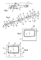
- the figure 1 presents a vehicle 1 provided with a carrying structure 2. More precisely, the vehicle is a rotorcraft type aircraft, the structure 2 representing the fuselage of this aircraft.
- This vehicle 1 is provided with a plurality of windows 3 closed by a transparent panel.
- the vehicle 1 is then provided with reversible fixing devices for bonding certain panels 5 to the structure 2.
- the adhesive beads used to attach a panel to a structure have specific dimensions, to the extent that the stresses exerted on the panels are demanding compared to the constraints observed in the automotive field in particular.
- the glue beads are therefore generally broad and thin, while the glue beads used in the automotive field are thick and small widths.
- the figure 2 has such a device 10 fixing.
- This device 10 comprises a plurality of pads 15 which can cooperate with a bead of glue.
- Each stud 15 is in particular provided with a body perforated longitudinally to present two longitudinal orifices 16.
- At least one stud 15 may comprise at least one self-adhesive face 20, 21 to facilitate its attachment to a panel or a structure.
- the device 10 includes two extraction son 30 able to cut a bead of glue.
- Each extraction wire may be of the "piano string” type.
- each extraction wire 30 passes through a longitudinal orifice 16 of each stud 15.
- Each extraction wire is then able to slide in a longitudinal hole of each stud
- Each extraction wire thus extends from a first end 36, 46 to a second end 38, 48, passing through a central portion 37, 47 which passes through the pads 15.
- each extraction wire is then arranged in a bead of adhesive 50 which is not visible on the figure 2 .
- first end 36, 46 and the second end 38, 48 of each extraction wire are not arranged in the bead of adhesive. An operator can therefore enter manually, or using a tool.
- each end 36, 46, 38, 48 may be provided with a gripping means 31 to facilitate its capture, such as a loop according to the example shown.
- Each gripping means 31 may be removable or integral with the associated end.
- an extraction wire is arranged in a longitudinal orifice 16 by inserting and pushing one end of the extraction wire 30 into the relevant longitudinal orifice.
- the pad is then made of a material that can be cut by the extraction wire following a manually exerted effort.
- This material may in particular be part of the group of elastomers.
- a stud may comprise a transverse groove 19 by longitudinal orifice.
- Each transverse groove communicates with the outside of the stud 15 to allow insertion and extraction of the extraction wire in the associated longitudinal orifice, in a direction called “direction transverse D1 "for convenience distinct from an extension direction D2 of the longitudinal orifice 16.
- the two longitudinal orifices may respectively constitute a longitudinal orifice called “internal longitudinal orifice 17" and a longitudinal orifice called “external longitudinal orifice 18".
- an extraction wire called for convenience “inner extraction wire 35” passes through all the inner longitudinal holes 17, while the other extraction wire referred to as convenience “Outer extraction wire 45” passes through all the outer longitudinal openings 18.
- this method aims to join two supports to one another with a bead of adhesive that can be cut.
- the method aims to secure a support 100 comprising a peripheral wall 4 defining a window 3, to another support comprising a peripheral surface to be glued a panel.
- a panel is optionally a transparent panel based on glass or plexiglass or equivalent.
- an operator distributes pads 15 on a support 100, in this case on the peripheral wall 4 according to the schematized example.
- the operator optimizes the distribution of the pads according to the geometry of the support.
- Each pad 15 may be centered on a geometrically medial axis AX separating the support into two parts of equal width.
- This step is all the easier to implement when the pads have a self-adhesive face.
- the inner extraction wire 35 is facing the inside INT of the vehicle, the outer extraction wire 45 being opposite the exterior EXT of the vehicle.
- the two extractions son 35, 45 do not cross.
- the operator has the ends 36, 38, 46, 48 outside the support to be bonded. These ends can be arranged in dedicated housing not shown.
- the operator then applies a bead of adhesive 50 to the support equipped with the pads 15, the pads 15 and the central portions of the extraction son being disposed within the bead of adhesive, and not within a seal.
- the support without the pads is then applied to the adhesive bead and the pads.
- the panel 5 and more precisely its peripheral surface to be glued on the adhesive bead.
- the panel 5 is thus bonded to the structure 2.
- first primer 61 attachment layer disposed on the wall 4, and a second primary layer 62 of attachment arranged on a peripheral surface 6 to stick the panel 5.
- each stud is substantially disposed in the center of the adhesive bead 50.
- an operator grasps manually or with the help of a tool the ends of an extraction wire. The operator then exerts a force on this extraction wire. For example, if the operator grasps the inner extraction wire 35, the operator exerts a force on this wire towards the inside of the vehicle according to the arrow F1 while going around the panel.
- the extraction wire then partially cuts the bead of glue.
- the operator By exerting a force towards the outside of the vehicle on the other extraction wire, the operator cuts the bead of glue in a new direction. For example, the operator exerts a force on the outer extraction wire 45 towards the outside of the vehicle according to the arrow F2.
- Part of the bead of adhesive remains attached to the structure 2 while the other part of the bead of adhesive remains attached to the panel 5.
- a manual pressure on the panel can completely separate the panel of the structure 2, to take off the pads or a possible portion of the bead of adhesive between the two extraction son.
- each extraction wire does not have the function of severing the entire width of the bead of adhesive. It thus becomes possible to easily cut cords of wide glue, of the type used in the aeronautical field in particular.
Landscapes
- Engineering & Computer Science (AREA)
- Mechanical Engineering (AREA)
- Aviation & Aerospace Engineering (AREA)
- Adhesives Or Adhesive Processes (AREA)
- Automobile Manufacture Line, Endless Track Vehicle, Trailer (AREA)
- Standing Axle, Rod, Or Tube Structures Coupled By Welding, Adhesion, Or Deposition (AREA)
- Window Of Vehicle (AREA)
- Body Structure For Vehicles (AREA)
Applications Claiming Priority (1)
| Application Number | Priority Date | Filing Date | Title |
|---|---|---|---|
| FR1104113A FR2984975B1 (fr) | 2011-12-27 | 2011-12-27 | Dispositif de fixation reversible d'un panneau a une structure pour obturer une fenetre de cette structure, vehicule et procede |
Publications (2)
| Publication Number | Publication Date |
|---|---|
| EP2610097A1 true EP2610097A1 (de) | 2013-07-03 |
| EP2610097B1 EP2610097B1 (de) | 2016-02-24 |
Family
ID=47115191
Family Applications (1)
| Application Number | Title | Priority Date | Filing Date |
|---|---|---|---|
| EP12007529.6A Active EP2610097B1 (de) | 2011-12-27 | 2012-11-06 | Wiederabnehmbare Befestigungsvorrichtung eines Paneels auf einer Struktur zum Abdichten eines Fensters dieser Struktur, Fahrzeug und Verfahren |
Country Status (3)
| Country | Link |
|---|---|
| US (1) | US9168723B2 (de) |
| EP (1) | EP2610097B1 (de) |
| FR (1) | FR2984975B1 (de) |
Cited By (2)
| Publication number | Priority date | Publication date | Assignee | Title |
|---|---|---|---|---|
| EP3421350A1 (de) * | 2017-06-30 | 2019-01-02 | Airbus Helicopters | Montageeinheit aus einem rahmen und einem zusatzelement, luftfahrzeug, das eine solche montageeinheit umfasst, und befestigungs- und entkopplungsverfahren einer solchen montageeinheit |
| EP4067674A1 (de) | 2021-03-30 | 2022-10-05 | Airbus Helicopters | Baugruppe mit zwei elementen, die durch eine klebeverbindung mit verschlossenen tunneln verbunden sind, fahrzeug mit einer solchen baugruppe und verfahren zum verbinden und lösen einer solchen baugruppe |
Families Citing this family (1)
| Publication number | Priority date | Publication date | Assignee | Title |
|---|---|---|---|---|
| US12358349B2 (en) | 2021-09-30 | 2025-07-15 | Magna Mirrors Of America, Inc. | Vehicle window assembly with bonded perimeter frame |
Citations (6)
| Publication number | Priority date | Publication date | Assignee | Title |
|---|---|---|---|---|
| DE3722657C1 (de) | 1987-07-09 | 1989-02-09 | Ver Glaswerke Gmbh | Verfahren zum Herstellen einer Ioesbaren Direktverklebung fuer eine Autoglasscheibe |
| EP0367662A2 (de) | 1988-10-31 | 1990-05-09 | Saint-Gobain Vitrage International | Kraftfahrzeugverglasung, deren Einbau durch Kleben vorgesehen ist und die mit einem vormontierten Ausziehdraht ausgerüstet ist |
| US5069012A (en) | 1989-02-25 | 1991-12-03 | Gurit-Essex Ag | Gap sealing means |
| FR2766156A1 (fr) | 1997-07-18 | 1999-01-22 | Eurocopter France | Encadrement de vitre permettant le largage d'un hublot d'helicoptere |
| DE20217925U1 (de) | 2002-11-19 | 2003-03-20 | Rennings, Manfred, 32657 Lemgo | Sicherheitsfenster mit Notfalleinrichtung für Busse und Bahnen |
| US6929844B2 (en) | 2001-04-14 | 2005-08-16 | Saint-Gobain Glass France | Window pane capable of bonding with tear-away cord |
Family Cites Families (2)
| Publication number | Priority date | Publication date | Assignee | Title |
|---|---|---|---|---|
| US5186807A (en) * | 1991-08-13 | 1993-02-16 | Erie Scientific Company | Electrophoresis gel slab cassettes having pull cords and methods |
| ES2292476T5 (es) * | 2000-10-10 | 2013-04-26 | Saint-Gobain Glass France | Utilización de un acristalamiento que comprende un cordón perfilado para su instalación en un hueco |
-
2011
- 2011-12-27 FR FR1104113A patent/FR2984975B1/fr not_active Expired - Fee Related
-
2012
- 2012-11-06 EP EP12007529.6A patent/EP2610097B1/de active Active
- 2012-12-17 US US13/716,537 patent/US9168723B2/en not_active Expired - Fee Related
Patent Citations (6)
| Publication number | Priority date | Publication date | Assignee | Title |
|---|---|---|---|---|
| DE3722657C1 (de) | 1987-07-09 | 1989-02-09 | Ver Glaswerke Gmbh | Verfahren zum Herstellen einer Ioesbaren Direktverklebung fuer eine Autoglasscheibe |
| EP0367662A2 (de) | 1988-10-31 | 1990-05-09 | Saint-Gobain Vitrage International | Kraftfahrzeugverglasung, deren Einbau durch Kleben vorgesehen ist und die mit einem vormontierten Ausziehdraht ausgerüstet ist |
| US5069012A (en) | 1989-02-25 | 1991-12-03 | Gurit-Essex Ag | Gap sealing means |
| FR2766156A1 (fr) | 1997-07-18 | 1999-01-22 | Eurocopter France | Encadrement de vitre permettant le largage d'un hublot d'helicoptere |
| US6929844B2 (en) | 2001-04-14 | 2005-08-16 | Saint-Gobain Glass France | Window pane capable of bonding with tear-away cord |
| DE20217925U1 (de) | 2002-11-19 | 2003-03-20 | Rennings, Manfred, 32657 Lemgo | Sicherheitsfenster mit Notfalleinrichtung für Busse und Bahnen |
Cited By (5)
| Publication number | Priority date | Publication date | Assignee | Title |
|---|---|---|---|---|
| EP3421350A1 (de) * | 2017-06-30 | 2019-01-02 | Airbus Helicopters | Montageeinheit aus einem rahmen und einem zusatzelement, luftfahrzeug, das eine solche montageeinheit umfasst, und befestigungs- und entkopplungsverfahren einer solchen montageeinheit |
| FR3068404A1 (fr) * | 2017-06-30 | 2019-01-04 | Airbus Helicopters | Assemblage entre un chassis et un element annexe,aeronef comportant un tel assemblage et procedes de solidarisation et de desolidarisation d'un tel assemblage |
| EP4067674A1 (de) | 2021-03-30 | 2022-10-05 | Airbus Helicopters | Baugruppe mit zwei elementen, die durch eine klebeverbindung mit verschlossenen tunneln verbunden sind, fahrzeug mit einer solchen baugruppe und verfahren zum verbinden und lösen einer solchen baugruppe |
| FR3121483A1 (fr) | 2021-03-30 | 2022-10-07 | Airbus Helicopters | Assemblage ayant deux éléments assemblés par un joint de colle muni de tunnels obturés, véhicule comportant un tel assemblage et procédés de solidarisation et de désolidarisation d’un tel assemblage |
| US12497154B2 (en) | 2021-03-30 | 2025-12-16 | Airbus Helicopters | Assembly having two elements assembled by a glue joint provided with blocked tunnels, vehicle comprising such an assembly and methods for securing and detaching such an assembly |
Also Published As
| Publication number | Publication date |
|---|---|
| FR2984975B1 (fr) | 2014-01-31 |
| EP2610097B1 (de) | 2016-02-24 |
| FR2984975A1 (fr) | 2013-06-28 |
| US9168723B2 (en) | 2015-10-27 |
| US20130164074A1 (en) | 2013-06-27 |
Similar Documents
| Publication | Publication Date | Title |
|---|---|---|
| FR2830236A1 (fr) | Dispositif de fixation d'un pare-brise d'aeronef | |
| CA2882819A1 (fr) | Systeme de joint pour vitrage de vehicule, vitrage equipe du systeme et procede de montage du vitrage | |
| EP2159154B1 (de) | Abgedichteter Fensterrahmen | |
| EP2610097B1 (de) | Wiederabnehmbare Befestigungsvorrichtung eines Paneels auf einer Struktur zum Abdichten eines Fensters dieser Struktur, Fahrzeug und Verfahren | |
| EP2293977B1 (de) | System zur sicherung von isolationsmatten in einem flugzeugrumpf | |
| EP1546276B1 (de) | Automatisiertes verfahren zur vorbereitung und herstellung von anfassern und einer schutzfolie sowie extrusionsprofil mit schutzfolie mit derartigen anfassern | |
| EP4158221B1 (de) | Verbindungsvorrichtung für kabelförderband mit kabelverriegelungselementen | |
| EP3915870B1 (de) | Vorrichtung zum abwurf eines flugzeugpaneels und entsprechendes flugzeug | |
| EP3421350B1 (de) | Montageeinheit aus einem rahmen und einem zusatzelement, luftfahrzeug, das eine solche montageeinheit umfasst, und befestigungs- und entkopplungsverfahren einer solchen montageeinheit | |
| CA2827452C (fr) | Dispositif de fixation d'un vitrage ouvrable par rotation, vitrage et procede de fabrication du vitrage | |
| EP1385713B1 (de) | Mit abreissschnur verbindbare fensterscheibe | |
| FR3020994A1 (fr) | Systeme de joint pour vitrage de vehicule, vitrage equipe du systeme et procede de montage du vitrage. | |
| EP4067674B1 (de) | Baugruppe mit zwei elementen, die durch eine klebeverbindung mit verschlossenen tunneln verbunden sind, fahrzeug mit einer solchen baugruppe und verfahren zum verbinden und lösen einer solchen baugruppe | |
| EP2747059A1 (de) | Selbstklebende Etiketten mit maskierter Sicherheitsmitteilung | |
| OA21151A (fr) | Dispositif de jonction de bande transporteuse à cables muni d'éléments de blocage de cable | |
| EP3727915B1 (de) | Dichtung für ein kraftfahrzeug umfassend mindestens einen befestigungsclip | |
| CA2722205C (fr) | Moyen de positionnement d'une premiere structure par rapport a une deuxieme structure, procede de positionnement et procede d'assemblage d'une premiere structure a une deuxieme structure | |
| EP4610501A1 (de) | Verbindung einer sandwichplatte mit einer struktur | |
| EP3476718A1 (de) | Abwerfbares fahrzeugfenster und fahrzeug mit einem solchen fenster | |
| FR2869257A1 (fr) | Procede automatise de fabrication d'une languette de prehension integree a une pellicule de protection d'une bande ou d'un cordon d'adhesif et profile extrude ou injecte comportant une telle languette | |
| EP2620659B1 (de) | Zubehörteil zum zusammenbau eines materials einer verbundstruktur, anordnung zum versehen einer verbundstruktur mit diesem zubehörteil und befestigungsverfahren eines solchen zubehörteils | |
| FR2744182A1 (fr) | Procede pour fixer un insert sur une structure sandwich constituee d'au moins deux panneaux a coller ensemble suivant un plan de joint peripherique, dispositif pour sa mise en oeuvre et structure equipee de ce dispositif | |
| FR2803327A1 (fr) | Procede et dispositif de fixation pour panneaux a double flancs | |
| FR3006921A1 (fr) | Procede d'assemblage des plaques |
Legal Events
| Date | Code | Title | Description |
|---|---|---|---|
| PUAI | Public reference made under article 153(3) epc to a published international application that has entered the european phase |
Free format text: ORIGINAL CODE: 0009012 |
|
| AK | Designated contracting states |
Kind code of ref document: A1 Designated state(s): AL AT BE BG CH CY CZ DE DK EE ES FI FR GB GR HR HU IE IS IT LI LT LU LV MC MK MT NL NO PL PT RO RS SE SI SK SM TR |
|
| AX | Request for extension of the european patent |
Extension state: BA ME |
|
| 17P | Request for examination filed |
Effective date: 20130801 |
|
| RBV | Designated contracting states (corrected) |
Designated state(s): AL AT BE BG CH CY CZ DE DK EE ES FI FR GB GR HR HU IE IS IT LI LT LU LV MC MK MT NL NO PL PT RO RS SE SI SK SM TR |
|
| RAP1 | Party data changed (applicant data changed or rights of an application transferred) |
Owner name: AIRBUS HELICOPTERS |
|
| GRAP | Despatch of communication of intention to grant a patent |
Free format text: ORIGINAL CODE: EPIDOSNIGR1 |
|
| INTG | Intention to grant announced |
Effective date: 20150626 |
|
| GRAS | Grant fee paid |
Free format text: ORIGINAL CODE: EPIDOSNIGR3 |
|
| REG | Reference to a national code |
Ref country code: DE Ref legal event code: R079 Ref document number: 602012014821 Country of ref document: DE Free format text: PREVIOUS MAIN CLASS: B60J0010020000 Ipc: B60J0010000000 |
|
| RIC1 | Information provided on ipc code assigned before grant |
Ipc: B60J 10/00 20160101AFI20151211BHEP |
|
| GRAA | (expected) grant |
Free format text: ORIGINAL CODE: 0009210 |
|
| AK | Designated contracting states |
Kind code of ref document: B1 Designated state(s): AL AT BE BG CH CY CZ DE DK EE ES FI FR GB GR HR HU IE IS IT LI LT LU LV MC MK MT NL NO PL PT RO RS SE SI SK SM TR |
|
| REG | Reference to a national code |
Ref country code: GB Ref legal event code: FG4D Free format text: NOT ENGLISH |
|
| REG | Reference to a national code |
Ref country code: CH Ref legal event code: EP |
|
| REG | Reference to a national code |
Ref country code: AT Ref legal event code: REF Ref document number: 776493 Country of ref document: AT Kind code of ref document: T Effective date: 20160315 |
|
| REG | Reference to a national code |
Ref country code: IE Ref legal event code: FG4D Free format text: LANGUAGE OF EP DOCUMENT: FRENCH |
|
| REG | Reference to a national code |
Ref country code: DE Ref legal event code: R096 Ref document number: 602012014821 Country of ref document: DE |
|
| REG | Reference to a national code |
Ref country code: LT Ref legal event code: MG4D |
|
| REG | Reference to a national code |
Ref country code: NL Ref legal event code: MP Effective date: 20160224 |
|
| REG | Reference to a national code |
Ref country code: AT Ref legal event code: MK05 Ref document number: 776493 Country of ref document: AT Kind code of ref document: T Effective date: 20160224 |
|
| PG25 | Lapsed in a contracting state [announced via postgrant information from national office to epo] |
Ref country code: FI Free format text: LAPSE BECAUSE OF FAILURE TO SUBMIT A TRANSLATION OF THE DESCRIPTION OR TO PAY THE FEE WITHIN THE PRESCRIBED TIME-LIMIT Effective date: 20160224 Ref country code: NO Free format text: LAPSE BECAUSE OF FAILURE TO SUBMIT A TRANSLATION OF THE DESCRIPTION OR TO PAY THE FEE WITHIN THE PRESCRIBED TIME-LIMIT Effective date: 20160524 Ref country code: GR Free format text: LAPSE BECAUSE OF FAILURE TO SUBMIT A TRANSLATION OF THE DESCRIPTION OR TO PAY THE FEE WITHIN THE PRESCRIBED TIME-LIMIT Effective date: 20160525 Ref country code: HR Free format text: LAPSE BECAUSE OF FAILURE TO SUBMIT A TRANSLATION OF THE DESCRIPTION OR TO PAY THE FEE WITHIN THE PRESCRIBED TIME-LIMIT Effective date: 20160224 Ref country code: ES Free format text: LAPSE BECAUSE OF FAILURE TO SUBMIT A TRANSLATION OF THE DESCRIPTION OR TO PAY THE FEE WITHIN THE PRESCRIBED TIME-LIMIT Effective date: 20160224 |
|
| PG25 | Lapsed in a contracting state [announced via postgrant information from national office to epo] |
Ref country code: RS Free format text: LAPSE BECAUSE OF FAILURE TO SUBMIT A TRANSLATION OF THE DESCRIPTION OR TO PAY THE FEE WITHIN THE PRESCRIBED TIME-LIMIT Effective date: 20160224 Ref country code: LV Free format text: LAPSE BECAUSE OF FAILURE TO SUBMIT A TRANSLATION OF THE DESCRIPTION OR TO PAY THE FEE WITHIN THE PRESCRIBED TIME-LIMIT Effective date: 20160224 Ref country code: PT Free format text: LAPSE BECAUSE OF FAILURE TO SUBMIT A TRANSLATION OF THE DESCRIPTION OR TO PAY THE FEE WITHIN THE PRESCRIBED TIME-LIMIT Effective date: 20160624 Ref country code: NL Free format text: LAPSE BECAUSE OF FAILURE TO SUBMIT A TRANSLATION OF THE DESCRIPTION OR TO PAY THE FEE WITHIN THE PRESCRIBED TIME-LIMIT Effective date: 20160224 Ref country code: SE Free format text: LAPSE BECAUSE OF FAILURE TO SUBMIT A TRANSLATION OF THE DESCRIPTION OR TO PAY THE FEE WITHIN THE PRESCRIBED TIME-LIMIT Effective date: 20160224 Ref country code: AT Free format text: LAPSE BECAUSE OF FAILURE TO SUBMIT A TRANSLATION OF THE DESCRIPTION OR TO PAY THE FEE WITHIN THE PRESCRIBED TIME-LIMIT Effective date: 20160224 Ref country code: PL Free format text: LAPSE BECAUSE OF FAILURE TO SUBMIT A TRANSLATION OF THE DESCRIPTION OR TO PAY THE FEE WITHIN THE PRESCRIBED TIME-LIMIT Effective date: 20160224 Ref country code: LT Free format text: LAPSE BECAUSE OF FAILURE TO SUBMIT A TRANSLATION OF THE DESCRIPTION OR TO PAY THE FEE WITHIN THE PRESCRIBED TIME-LIMIT Effective date: 20160224 |
|
| PG25 | Lapsed in a contracting state [announced via postgrant information from national office to epo] |
Ref country code: DK Free format text: LAPSE BECAUSE OF FAILURE TO SUBMIT A TRANSLATION OF THE DESCRIPTION OR TO PAY THE FEE WITHIN THE PRESCRIBED TIME-LIMIT Effective date: 20160224 Ref country code: EE Free format text: LAPSE BECAUSE OF FAILURE TO SUBMIT A TRANSLATION OF THE DESCRIPTION OR TO PAY THE FEE WITHIN THE PRESCRIBED TIME-LIMIT Effective date: 20160224 |
|
| REG | Reference to a national code |
Ref country code: FR Ref legal event code: PLFP Year of fee payment: 5 |
|
| REG | Reference to a national code |
Ref country code: DE Ref legal event code: R097 Ref document number: 602012014821 Country of ref document: DE |
|
| PG25 | Lapsed in a contracting state [announced via postgrant information from national office to epo] |
Ref country code: RO Free format text: LAPSE BECAUSE OF FAILURE TO SUBMIT A TRANSLATION OF THE DESCRIPTION OR TO PAY THE FEE WITHIN THE PRESCRIBED TIME-LIMIT Effective date: 20160224 Ref country code: SK Free format text: LAPSE BECAUSE OF FAILURE TO SUBMIT A TRANSLATION OF THE DESCRIPTION OR TO PAY THE FEE WITHIN THE PRESCRIBED TIME-LIMIT Effective date: 20160224 Ref country code: SM Free format text: LAPSE BECAUSE OF FAILURE TO SUBMIT A TRANSLATION OF THE DESCRIPTION OR TO PAY THE FEE WITHIN THE PRESCRIBED TIME-LIMIT Effective date: 20160224 Ref country code: CZ Free format text: LAPSE BECAUSE OF FAILURE TO SUBMIT A TRANSLATION OF THE DESCRIPTION OR TO PAY THE FEE WITHIN THE PRESCRIBED TIME-LIMIT Effective date: 20160224 |
|
| PLBE | No opposition filed within time limit |
Free format text: ORIGINAL CODE: 0009261 |
|
| STAA | Information on the status of an ep patent application or granted ep patent |
Free format text: STATUS: NO OPPOSITION FILED WITHIN TIME LIMIT |
|
| 26N | No opposition filed |
Effective date: 20161125 |
|
| PG25 | Lapsed in a contracting state [announced via postgrant information from national office to epo] |
Ref country code: BE Free format text: LAPSE BECAUSE OF NON-PAYMENT OF DUE FEES Effective date: 20161130 Ref country code: BG Free format text: LAPSE BECAUSE OF FAILURE TO SUBMIT A TRANSLATION OF THE DESCRIPTION OR TO PAY THE FEE WITHIN THE PRESCRIBED TIME-LIMIT Effective date: 20160524 Ref country code: SI Free format text: LAPSE BECAUSE OF FAILURE TO SUBMIT A TRANSLATION OF THE DESCRIPTION OR TO PAY THE FEE WITHIN THE PRESCRIBED TIME-LIMIT Effective date: 20160224 |
|
| REG | Reference to a national code |
Ref country code: DE Ref legal event code: R119 Ref document number: 602012014821 Country of ref document: DE |
|
| REG | Reference to a national code |
Ref country code: CH Ref legal event code: PL |
|
| PG25 | Lapsed in a contracting state [announced via postgrant information from national office to epo] |
Ref country code: CH Free format text: LAPSE BECAUSE OF NON-PAYMENT OF DUE FEES Effective date: 20161130 Ref country code: LI Free format text: LAPSE BECAUSE OF NON-PAYMENT OF DUE FEES Effective date: 20161130 |
|
| REG | Reference to a national code |
Ref country code: IE Ref legal event code: MM4A |
|
| PG25 | Lapsed in a contracting state [announced via postgrant information from national office to epo] |
Ref country code: LU Free format text: LAPSE BECAUSE OF NON-PAYMENT OF DUE FEES Effective date: 20161130 |
|
| REG | Reference to a national code |
Ref country code: FR Ref legal event code: PLFP Year of fee payment: 6 |
|
| PG25 | Lapsed in a contracting state [announced via postgrant information from national office to epo] |
Ref country code: DE Free format text: LAPSE BECAUSE OF NON-PAYMENT OF DUE FEES Effective date: 20170601 Ref country code: IE Free format text: LAPSE BECAUSE OF NON-PAYMENT OF DUE FEES Effective date: 20161106 |
|
| REG | Reference to a national code |
Ref country code: BE Ref legal event code: MM Effective date: 20161130 |
|
| PG25 | Lapsed in a contracting state [announced via postgrant information from national office to epo] |
Ref country code: CY Free format text: LAPSE BECAUSE OF FAILURE TO SUBMIT A TRANSLATION OF THE DESCRIPTION OR TO PAY THE FEE WITHIN THE PRESCRIBED TIME-LIMIT Effective date: 20160224 Ref country code: HU Free format text: LAPSE BECAUSE OF FAILURE TO SUBMIT A TRANSLATION OF THE DESCRIPTION OR TO PAY THE FEE WITHIN THE PRESCRIBED TIME-LIMIT; INVALID AB INITIO Effective date: 20121106 |
|
| PG25 | Lapsed in a contracting state [announced via postgrant information from national office to epo] |
Ref country code: TR Free format text: LAPSE BECAUSE OF FAILURE TO SUBMIT A TRANSLATION OF THE DESCRIPTION OR TO PAY THE FEE WITHIN THE PRESCRIBED TIME-LIMIT Effective date: 20160224 Ref country code: MK Free format text: LAPSE BECAUSE OF FAILURE TO SUBMIT A TRANSLATION OF THE DESCRIPTION OR TO PAY THE FEE WITHIN THE PRESCRIBED TIME-LIMIT Effective date: 20160224 Ref country code: IS Free format text: LAPSE BECAUSE OF FAILURE TO SUBMIT A TRANSLATION OF THE DESCRIPTION OR TO PAY THE FEE WITHIN THE PRESCRIBED TIME-LIMIT Effective date: 20160224 Ref country code: MC Free format text: LAPSE BECAUSE OF FAILURE TO SUBMIT A TRANSLATION OF THE DESCRIPTION OR TO PAY THE FEE WITHIN THE PRESCRIBED TIME-LIMIT Effective date: 20160224 |
|
| PG25 | Lapsed in a contracting state [announced via postgrant information from national office to epo] |
Ref country code: MT Free format text: LAPSE BECAUSE OF FAILURE TO SUBMIT A TRANSLATION OF THE DESCRIPTION OR TO PAY THE FEE WITHIN THE PRESCRIBED TIME-LIMIT Effective date: 20160224 |
|
| PG25 | Lapsed in a contracting state [announced via postgrant information from national office to epo] |
Ref country code: AL Free format text: LAPSE BECAUSE OF FAILURE TO SUBMIT A TRANSLATION OF THE DESCRIPTION OR TO PAY THE FEE WITHIN THE PRESCRIBED TIME-LIMIT Effective date: 20160224 |
|
| PGFP | Annual fee paid to national office [announced via postgrant information from national office to epo] |
Ref country code: GB Payment date: 20221125 Year of fee payment: 11 |
|
| P01 | Opt-out of the competence of the unified patent court (upc) registered |
Effective date: 20230530 |
|
| GBPC | Gb: european patent ceased through non-payment of renewal fee |
Effective date: 20231106 |
|
| PG25 | Lapsed in a contracting state [announced via postgrant information from national office to epo] |
Ref country code: GB Free format text: LAPSE BECAUSE OF NON-PAYMENT OF DUE FEES Effective date: 20231106 |
|
| PG25 | Lapsed in a contracting state [announced via postgrant information from national office to epo] |
Ref country code: GB Free format text: LAPSE BECAUSE OF NON-PAYMENT OF DUE FEES Effective date: 20231106 |
|
| PGFP | Annual fee paid to national office [announced via postgrant information from national office to epo] |
Ref country code: IT Payment date: 20251125 Year of fee payment: 14 |
|
| PGFP | Annual fee paid to national office [announced via postgrant information from national office to epo] |
Ref country code: FR Payment date: 20251125 Year of fee payment: 14 |