EP2610103A1 - Procédé et dispositif de commande d'un actionneur et système de protection de passagers - Google Patents
Procédé et dispositif de commande d'un actionneur et système de protection de passagers Download PDFInfo
- Publication number
- EP2610103A1 EP2610103A1 EP12199384.4A EP12199384A EP2610103A1 EP 2610103 A1 EP2610103 A1 EP 2610103A1 EP 12199384 A EP12199384 A EP 12199384A EP 2610103 A1 EP2610103 A1 EP 2610103A1
- Authority
- EP
- European Patent Office
- Prior art keywords
- actuator
- signal
- occupant protection
- trigger
- protection device
- Prior art date
- Legal status (The legal status is an assumption and is not a legal conclusion. Google has not performed a legal analysis and makes no representation as to the accuracy of the status listed.)
- Withdrawn
Links
- 238000000034 method Methods 0.000 title claims description 20
- 238000004590 computer program Methods 0.000 claims abstract description 5
- 230000000903 blocking effect Effects 0.000 claims description 17
- 230000004044 response Effects 0.000 claims description 7
- 230000006870 function Effects 0.000 description 16
- 238000010586 diagram Methods 0.000 description 10
- 238000012544 monitoring process Methods 0.000 description 9
- 230000004913 activation Effects 0.000 description 5
- 230000003213 activating effect Effects 0.000 description 4
- 230000010354 integration Effects 0.000 description 4
- 238000003745 diagnosis Methods 0.000 description 3
- 230000007257 malfunction Effects 0.000 description 3
- 230000001960 triggered effect Effects 0.000 description 3
- 238000006073 displacement reaction Methods 0.000 description 2
- 208000007623 Lordosis Diseases 0.000 description 1
- 230000001133 acceleration Effects 0.000 description 1
- 230000000454 anti-cipatory effect Effects 0.000 description 1
- 238000013459 approach Methods 0.000 description 1
- 230000008901 benefit Effects 0.000 description 1
- 230000007613 environmental effect Effects 0.000 description 1
- 238000011156 evaluation Methods 0.000 description 1
- 230000002401 inhibitory effect Effects 0.000 description 1
- 238000003780 insertion Methods 0.000 description 1
- 230000037431 insertion Effects 0.000 description 1
- 230000032297 kinesis Effects 0.000 description 1
- 230000006855 networking Effects 0.000 description 1
- 230000003287 optical effect Effects 0.000 description 1
- 230000008569 process Effects 0.000 description 1
- 239000004065 semiconductor Substances 0.000 description 1
Images


Classifications
-
- B—PERFORMING OPERATIONS; TRANSPORTING
- B60—VEHICLES IN GENERAL
- B60N—SEATS SPECIALLY ADAPTED FOR VEHICLES; VEHICLE PASSENGER ACCOMMODATION NOT OTHERWISE PROVIDED FOR
- B60N2/00—Seats specially adapted for vehicles; Arrangement or mounting of seats in vehicles
- B60N2/02—Seats specially adapted for vehicles; Arrangement or mounting of seats in vehicles the seat or part thereof being movable, e.g. adjustable
- B60N2/0224—Non-manual adjustments, e.g. with electrical operation
- B60N2/0244—Non-manual adjustments, e.g. with electrical operation with logic circuits
- B60N2/0276—Non-manual adjustments, e.g. with electrical operation with logic circuits reaction to emergency situations, e.g. crash
-
- B—PERFORMING OPERATIONS; TRANSPORTING
- B60—VEHICLES IN GENERAL
- B60R—VEHICLES, VEHICLE FITTINGS, OR VEHICLE PARTS, NOT OTHERWISE PROVIDED FOR
- B60R21/00—Arrangements or fittings on vehicles for protecting or preventing injuries to occupants or pedestrians in case of accidents or other traffic risks
- B60R21/01—Electrical circuits for triggering passive safety arrangements, e.g. airbags, safety belt tighteners, in case of vehicle accidents or impending vehicle accidents
-
- B—PERFORMING OPERATIONS; TRANSPORTING
- B60—VEHICLES IN GENERAL
- B60R—VEHICLES, VEHICLE FITTINGS, OR VEHICLE PARTS, NOT OTHERWISE PROVIDED FOR
- B60R21/00—Arrangements or fittings on vehicles for protecting or preventing injuries to occupants or pedestrians in case of accidents or other traffic risks
- B60R21/01—Electrical circuits for triggering passive safety arrangements, e.g. airbags, safety belt tighteners, in case of vehicle accidents or impending vehicle accidents
- B60R2021/01204—Actuation parameters of safety arrangents
- B60R2021/01252—Devices other than bags
Definitions
- the present invention relates to a method for controlling an actuator of a seat-based occupant protection device of a vehicle, to a corresponding device and to a corresponding computer program product and to an occupant protection system.
- the WO 2004 103 779 A1 describes an occupant protection system for vehicles, having a seat adjustment device with at least one actuator for adjusting a seat.
- the present invention provides a method for controlling an actuator of a seat-based occupant protection device of a vehicle, a device that uses this method, an occupant protection system, and finally a corresponding computer program product according to the main claims.
- Advantageous embodiments emerge from the respective subclaims and the following description.
- a seat-based occupant protection device of a vehicle may be deployed in an accident to protect an occupant of the vehicle.
- an actuator can be used to trigger the occupant protection device.
- a suitable control of the actuator By a suitable control of the actuator, a correct use of the actuator and thus also the occupant protection device can be ensured. If a malfunction is detected that leads to an erroneous operation of the occupant protection device, the actuator may be disabled to prevent the erroneous operation of the occupant protection device.
- a method for controlling an actuator of a seat-based occupant protection device of a vehicle comprises the following steps:
- a trigger signal that is configured to indicate a triggering decision to trigger the seat-based occupant protection device
- the vehicle may be a passenger vehicle, such as a passenger car, or a truck.
- the seat-based occupant protection device may be an occupant protection device coupled to a seat of the vehicle.
- the occupant protection device may comprise, for example, a device for active seat adjustment.
- the occupant protection device may be actuated in the event of an accident of the vehicle to protect the occupant.
- the actuator may be configured to actuate an element of the occupant protection device, for example to move.
- the actuator may include a motor for actuating the occupant protection device.
- the triggering decision can be made, for example, in response to a detected or imminent accident of the vehicle by a suitable tripping logic. In response to the triggering decision transmitted by the trigger signal, the actuator may be activated to actuate the occupant protection device.
- the lock can also act when a trigger signal is present.
- the inhibit signal may be output directly to the actuator or to means for controlling operation of the actuator.
- the enable signal may include information about the actuator or occupant protection device that may be used with the trigger signal to trigger or suspend a lock on the actuator.
- the Blocking signal provides redundancy in activating or blocking the occupant protection device.
- the inhibit signal may be suitable for interrupting a power supply of the actuator.
- the inhibit signal may be suitable to control closing or opening of a switch.
- the switch may be configured to interrupt or release the power supply of the actuator. If the power supply of the actuator is interrupted, the occupant protection device can not be actuated despite an existing triggering decision.
- a device for interrupting the power supply which can be controlled by the blocking signal, can be realized simply and inexpensively.
- the release signal may be configured to indicate a period of time after a deployment of the occupant protection device.
- the disable signal for disabling the actuator may be generated depending on the time period indicated by the enable signal.
- a start of the time period may coincide with a start of the deployment of the occupant protection device or with a meeting of the deployment decision for the occupant protection device.
- the enable signal may continuously transmit time values indicating how long the occupant protection device has already been triggered. If the time duration is predetermined, the enable signal may indicate a lapse of the time duration. In this way, the actuator can be locked, for example, when reaching or exceeding the time period, although the trigger decision is still valid. In this way, an over-actuation of the actuator or the occupant protection device can be prevented.
- the enable signal may be configured to indicate a state of power supply of the actuator.
- the inhibit signal may be generated if the trigger signal does not indicate a trigger decision to trigger the occupant protection device and the enable signal indicates a power supply suitable for triggering the occupant protection device.
- the enable signal can indicate whether an operating voltage suitable for operating the actuator is applied to the actuator.
- the enable signal may indicate whether a power supply for the actuator is on or off. In this way, the actuator can be locked, if there is no valid triggering decision for the occupant protection device.
- the enable signal may be configured to indicate an operating state of the actuator.
- the inhibit signal may be generated if the trigger signal does not indicate a trigger decision to trigger the occupant protection device and the enable signal indicates operation of the actuator. In this way, a false activation of the actuator can be detected and the actuator can be locked on it.
- the enable signal may be configured to indicate an actuation state of the actuator.
- the step of generating the blocking signal can be generated when the trigger signal indicates a triggering decision for triggering the occupant protection device and the release signal indicating a different state of an operating state of the occupant protection device.
- the inhibit signal can be generated when the enable signal indicates that the target state is exceeded.
- the actuation state may, for example, characterize a position, for example an adjustment position or an extension position of an element of the actuator, or an adjustment path.
- the desired state may indicate a final state of an actuation of the actuator, for example an end position or a maximum displacement. In this way, the actuator can be released in an existing triggering decision until the desired state is reached. When reaching or exceeding the desired state of the actuator can then be disabled despite the present trigger decision.
- a value of the desired state can be received in the step of receiving.
- the desired state for example, be adapted to a recent accident.
- the present invention further provides a device for controlling an actuator of a seat-based occupant protection device of a vehicle, which is designed to implement or implement the steps of the method according to the invention in corresponding devices. Also by this embodiment of the invention in the form of a device, the object underlying the invention can be solved quickly and efficiently.
- a device can be understood as meaning an electrical device, for example a control device, which processes sensor signals and outputs control and / or data signals as a function thereof.
- the device may have an interface, which may be formed in hardware and / or software.
- the interfaces can be part of a so-called system ASIC, for example, which contains a wide variety of functions of the device.
- the interfaces are their own integrated circuits or at least partially consist of discrete components.
- the interfaces may be software modules that are present, for example, on a microcontroller in addition to other software modules.
- a computer program product with program code which can be stored on a machine-readable carrier such as a semiconductor memory, a hard disk memory or an optical memory and is used to carry out the method according to one of the embodiments described above if the program is installed on a computer or a device is also of advantage is performed.
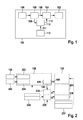
- Fig. 1 shows a schematic representation of a vehicle 100 according to an embodiment of the present invention.
- the vehicle 100 has an occupant protection means 102, which is triggered or actuated via an actuator 104.
- the actuator 104 is coupled to the occupant protection means 102.
- the vehicle 100 has a sensor 106 and a triggering logic 108.
- the sensor 106 is configured to provide a sensor signal to the tripping logic 108.
- the sensor 106 may be a sensor that detects an already or an imminent collision of the vehicle 100 can.
- the trigger logic 108 is configured to make a trigger decision for the occupant protection means 102 based on the sensor signal and to output a trigger signal 109 to the actuator 104.
- the actuator 104 is configured to actuate or actuate the occupant protection means 102 in response to the trigger signal 109.
- the actuator 104 may include a motor that operates in response to the trigger signal 109.
- the vehicle 100 has a device 110 for controlling the actuator 104 of the occupant protection device 102.
- the device 110 is configured to receive the trigger signal 109 from the trigger logic 108 and an enable signal 111 from an enable device 112 and to make a decision based on the trigger signal 109 and the enable signal 111 as to whether the actuator 104 should be disabled or not. When the actuator 104 is blocked, the actuator 104 can not actuate or trigger the occupant protection means 102.
- the device 110 is designed to output a blocking signal 113 to the actuator 104, depending on the decision about blocking or not blocking the actuator 104.
- the disable signal 113 has a first state when the actuator 104 is to be disabled and a second state when the actuator 104 is not to be disabled.
- the release device 112 is configured to generate the release signal 111 depending on a state of the actuator 104 or a timing of activation of the actuator 104 or the occupant protection device 102.
- the blocking signal 113 a tripping decision made by the tripping logic 108 can be revised.
- the actuator 104 can be disabled by the lock signal 113 when the trigger logic 108 has triggered no actuation of the actuator 104 via the trigger signal 109 and the operation of the actuator 104 is nevertheless detected by the release device 112.
- the occupant protection means 102 may be any occupant protection means or restraint means. Exemplary embodiments of devices for the redundant activation of seat-based restraint devices will be described below.
- the occupant protection means 102 may be a seat-based restraint that can bring a seat of the vehicle 100 into a crash-optimal position by rapid adjustment.
- the occupant protection means 102 can also be an anticipatory, pre-triggering system which pre-accelerates the occupant in the front crash by means of airbag or shoulder belt in the pre-crash phase in such a way that the speed is destructively superimposed by the crash pulse and the speed of the pre-acceleration.
- the actuator 104 may be an electromotive seat-based actuator, which is designed to significantly influence the kinesis of the occupant in the precrash phase.
- a protection of an occupant protection means 102 such as a seat-based occupant protection device can be realized, so that certain single errors can be intercepted in the system.
- a device is particularly useful if the occupant kinetics can be particularly influenced by the actuator 104, z. B. by a pre-accelerating system that gives the occupant a strong impulse.
- Fig. 2 shows a block diagram of a system for controlling restraint means according to an embodiment of the present invention.
- CAIS system crash-active intelligent seat system
- the system can be found in the in Fig. 1 be arranged vehicle shown.
- the system comprises, in addition to a sensor 106, a tripping logic 108, for example in the form of an airbag / safety ECU and an actuator 104, a further sensor 206, a further actuator 204 and further devices, which are described in more detail below.
- the devices 104, 106, 108 may be those based on Fig. 1 may be described
- the trip logic is implemented as a safety controller 108 and includes a vehicle dynamics module 222, a situation interpretation device 224, and a trigger decision device 226.
- the safety controller 108 may be implemented as an integrated circuit, for example in the form of an ASIC or FPGA.
- the sensor 106 is according to this embodiment representative of one or more Intertialsensoren and the sensor 206 for one or more environmental sensors.
- the sensor 106 is configured to output a sensor signal to the vehicle dynamics module 222.
- the vehicle dynamics module 222 is configured to determine a dynamics of the vehicle based on the sensor signal.
- the sensor 206 is configured to output another sensor signal to the situation interpretation device 224.
- the situation interpretation device 224 is configured to interpret a current situation in which the vehicle is located based on the further sensor signal.
- the trigger decision device 226 is designed to make a triggering decision for one or more occupant protection means based on the data of the sensors 106, 206 provided to the trigger logic 108 and to output corresponding trigger signals 109 for activating the actuators 104, 204.
- the actuator 104 is representative of one or a plurality of actuators for actuating a side stop function of a seat of the vehicle, for example in the form of Enveloping Side Adjustment actuators (ESA).
- ESA Enveloping Side Adjustment actuators
- the actuator 104 is configured to receive a trigger signal 109 directly from the trigger decision device 226.
- the actuator 104 is connected via an electrical line to a power supply 230.
- the power supply 230 may be a standard 13V power supply or a power supply greater than 13V according to an extended concept.
- the actuator 104 is configured to perform its actuator function when the actuator 104 is powered by the power supply 230 and receives the trigger signal 109.
- the actuator 204 is representative of one or a plurality of actuators for adjusting Verstellbenen the seat, for example in the form of accelerated seat adjustment actuators (ASA).
- ASA accelerated seat adjustment actuators
- a control device 232 in the form of a seat control device (Seat ECU CAIS) for a Crash Active Smart Seat (CAIS).
- the control device 232 is designed to receive a trigger signal 109 from the trigger decision device 226 and to provide energy in the form of a signal "power" to the actuator 204 depending thereon.
- the actuator 204 is configured to perform its actuator function when the actuator 204 is powered by the controller 232.
- the actuator 204 is configured to output a signal to the controller 232.
- the system further includes an adjustment switch 234, a control device 236 in the form of a comfort ECU (Seat-ECU comfort) and actuators 238 for comfort functions such as lordosis or massage.
- the setting switch 234 may be operated, for example, by an occupant of the vehicle.
- the setting switch 234 is configured to output a switching signal representing a switching position of the setting switch 234 to the safety controller 108 as well as to the controller 236.
- the switching signal, and thus a state of the actuators 238, may be used by trigger decision device 226 to make the trip decision.
- the control device 236 is designed to provide energy for actuating the actuators 238 to the actuators 238 depending on the switching signal.
- the controllers 232, 236 are powered by the power supply 230 via a line.
- the actuators 238 are configured to output a signal to the controller 236.
- the devices 206, 224, 104, 204, 238, 234, 232, 236 are optional and may be eliminated or replaced with other suitable devices.
- the devices 106, 206 are sensors.
- the devices 104, 204, 238 are actuators.
- the devices 108, 232, 236 are each a control unit.
- the devices 222, 224, 226 may be implemented as software modules.
- a seat-based system as in Fig. 2 is shown, characterized by a high level of networking.
- the adjustment of Verstellbenen, for example, the seat-length adjustment, seat tilt, seat height and seat back angle, actuators 204 (ASA)) is requested in a precrash scenario of the safety controller 108 via triggers and possibly by specifying a desired position and on the Seat control unit 232 finally implemented.
- the functionality of the actuators 104 (ESA) is not controlled by the seat control device, but is requested directly by the safety controller 108 and implemented in private electronics on the actuator 104.
- Fig. 3 shows a block diagram of the system for controlling restraint means, as already described with reference to Fig. 2 is described. Not shown in Fig. 3 the sensors and the corresponding evaluation devices of the safety controller 108. According to the in Fig. 3 In the embodiment shown, the system has, in addition to those already described with reference to Fig. 2 described features two switches 341, 343 on.
- the switch 341 is disposed in a power supply line connecting the power supply 230 to the actuator 104.
- the switch 341 When the switch 341 is closed, the actuator 104 is powered by the power supply 230 via the power supply line. If the switch 341 is opened, the actuator 104 is not supplied with energy and is thus blocked.
- the switch 343 is disposed in another power supply line that connects the seat controller 232 to the actuator 204. If the switch 343 is closed, the actuator 204 is powered by the seat control unit 232 via the further power supply line. If the switch 343 is open, the actuator 204 is not supplied with energy and is thus blocked.
- a switching position of the switches 341, 343 may be controlled by a device for controlling the actuators 104, 204, as shown in FIG Fig. 1 is shown and described in more detail in the following figures.
- an insertion of hardware switches 341, 343 for the function ASA, which is assigned to the actuator 204, and the function ESA, which is assigned to the actuator 104, take place.
- the ASA hardware switch 343 may also be relocated to the integration node of the seat controller 232.
- the ESA hardware switch 341 may also be placed in the integration node of the ESA actuator 104.
- Fig. 4 shows a block diagram of a system for controlling restraint means according to an embodiment of the present invention.
- the system includes a safety controller 108 having a trigger 226, an actuator 204 (ASA), and a seat controller 232 and a switch 343, which may be the devices already described with reference to the preceding figures, the description of which is hereby incorporated by reference ,
- the safety controller 108 has, in addition to the trigger 226, a diagnostic device 451 in the form of a CAIS diagnosis and a release logic 453 in the form of a CAIS release logic.
- the devices 451, 453 may be part of a device for controlling the actuator 204, as described with reference to FIG Fig. 1 is described.
- the seat controller 232 includes logic 455 and power supply 457.
- the actuator 204 is configured to output an adjustment information from the actuator 204.
- the logic 455 and the diagnostic device 451 are configured to receive the adjustment information from the actuator 204.
- the logic 455 is configured to determine an actual position of the actuator 204 based on the adjustment information from the actuator 204 and output to the trigger 226.
- the trigger 226 is configured to determine both a trigger signal 109 or a trigger signal and a desired position for the actuator 204 and output to the logic 455.
- the logic 455 is configured to output a control signal to the power supply 457 depending on the trigger signal 109 and the desired position that the logic 455 receives from the trigger 226 and the actual position.
- the power supply 457 is configured to receive the control signal from the logic 455 and, depending thereon, provide power to operate the actuator 204 via a line to the actuator 204.
- the logic 455 is configured to output the control signal for activating the power supply 457 for the actuator 204 when the trigger 226 indicates activation of the actuator 204 and the actuator 206 has not yet reached the target position.
- the diagnostic device 451 is configured to receive the adjustment information from the actuator 204 and the trigger signal 109 from the trigger 226 and based thereon to generate and output to the enable logic 453 an enable signal 111.
- the enable logic 453 is configured to receive, in addition to the enable signal 111 of the diagnostic device 451, the trigger signal 109 from the trigger 226 and, based thereon, to generate and output to the switch 343 a switching signal 113 for switching the switch 343.
- the switch 343 is opened or closed, so that the actuator 204 either is not supplied with power or is supplied with energy via the switch 343. If the switching signal 113 causes an opening of the switch 343, it acts as a blocking signal for the actuator 204. If the actuator 204 is not supplied with energy, a function of the actuator 204 is blocked.
- the release logic 453 is designed to perform an opening of the switch 343 and thus a blocking of the actuator 204 depending on an operating state or operating state of the actuator 204 displayed via the adjustment information of the actuator 204.
- the actuator 204 may be disabled when the trigger 226 does not provide a trigger signal 109 to actuate the actuator 204, but the actuator 204 adjustment information indicates actuation of the actuator 204.
- the actuator 204 may be disabled, for example, when an adjustment position of the actuator 204 determined from the adjustment information of the actuator 204 indicates that the target position of the actuator 204 has been reached or exceeded, although the trigger 226 continues to actuate the trigger signal 109 to actuate the actuator Actuator 204 is provided.
- a monitoring of the actuator 204 is realized. Based on the monitoring of the actuator 204, the switch 343 may be controlled. This approach may similarly or additionally can also be used for other actuators and other switches, as for example with reference to Fig. 6 is shown.
- the diagnostic device 451 and the release logic 453 are included to ensure that, on the one hand, the displacement path of the actuator 204 does not exceed the intended range and, on the other hand, that the seat is quickly adjusted by the actuator 204 only if the trigger 109 is moved through the Trigger 226 has been set.
- the adjustment can be limited time-controlled. For this purpose, no signal from the seat control unit 232 or the actuator 204 is necessary.
- the diagnostic device 451 is designed to interrupt the supply of the actuator 204 via the enable logic 453 in the pre-crash case in which the trigger 109 is present.
- the safety controller 108 offers itself as an integration node for the logic 451, 453, since on the one hand the trigger decision in the trigger 226 is made here. Furthermore, the safety control unit 108 is powerful enough to calculate a diagnosis and last but not least, this system is already designed sufficiently robust as a safety-critical system.
- a suitable architecture of the monitoring unit is presented on the basis of the exemplary embodiments shown in the following figures.
- FIG Fig. 5 A detailed interconnection, shown by way of example for the function ASA, is shown in FIG Fig. 5 shown.
- a malfunction of the seat control unit 457 for example, causes a high adjustment without trigger 109 by the safety controller 108 can be detected by the diagnostic device 451.
- the system may be stopped by the enable logic 453 after a very short adjustment.
- the CAIS diagnostic module 451 in the safety controller 108 is configured to monitor the raw information of the actuator 204.
- the raw information which can be provided for example via the adjustment information from the actuator 204, it may, for. B. act Hall signals of a coupled to the actuator 204 Hall sensor, of which a certain number per motor rotation of a motor of the actuator 204 is generated. If the pulse train signals a very rapid adjustment of the actuator 204, without the trigger 109 of the trigger 226 is applied, the CAIS release 453 is designed to lock the switch 343 after the final stage, for example in the form of the power supply 457.
- the diagnostic device 451 may additionally or alternatively be designed to count HallImpuls of the actuator 204 for redundant path limitation and to interrupt the power supply of the actuator 204 via a defined opening of the switch 343 from a defined number of Hall pulses.
- Fig. 5 shows a block diagram of a system for controlling restraint means according to an embodiment of the present invention.
- the system is the same as for Fig. 4 shown embodiment with the difference that the diagnostic device 451 does not receive the adjustment information from the actuator 204, but a tap of the power amplifier 457 supply.
- the diagnostic device 451 is coupled via a line to the supply line between the switch 343 and the actuator 204.
- the diagnostic device 451 is configured to receive a signal as to whether or not the actuator 204 is currently being powered.
- the diagnostic device 451 is designed to receive the tap of the supply of the output stage 457 and the trigger signal 109 from the trigger 226 and, based thereon, to generate and output to the enable logic 453 an enable signal 111.
- the release logic 453 is designed to perform an opening of the switch 343 and thus a blocking of the actuator 204 depending on a state of a power supply of the actuator 204 indicated via the tap of the supply of the output stage 457. So can for example, the actuator 204 may be disabled when the trigger 226 does not provide a trigger signal 109 to actuate the actuator 204, but the tap of power amp 457 indicates a power supply to the actuator 204 suitable for operating the actuator 204.
- the device 451, 453 for controlling the actuator 204 may analyze the power supply of the actuator 204. If the power supply corresponds to a rapid adjustment of the actuator 204, the supply of the actuator 204 is interrupted if the trigger signal of the trigger 226 is missing.
- the switch 343 is integrated into the seat control unit 232 and the monitoring unit 451, 453 is integrated into the safety control unit 108.
- Fig. 6 shows a block diagram of a system for controlling restraint means according to an embodiment of the present invention.
- the system comprises a safety controller, an actuator 104 (ESA), a power supply 230 and a switch 341.
- the safety controller 108 comprises a trigger 226, a diagnostic device 451 in the form of a CAIS diagnosis and a release logic 453 in the form of a CAIS release logic.
- the safety controller 108 corresponds to the already with reference to the FIGS. 4 and 5 described safety control device.
- the actuator 104, the switch 341 and the power supply 230 are those already described with reference to FIG Fig. 3 described elements.
- the actuator 104 is designed as an actuator for the function ESA.
- the power supply 230 is configured to continuously provide power to operate the actuator 104 via a line to the actuator 104.
- the switch 341 is arranged. When the switch 341 is opened, the power supply of the actuator 104 is interrupted and the actuator 104 is disabled.
- the trigger 226 is configured to determine a trigger signal 109 or a trigger signal for the actuator 104 and output to the actuator 104.
- the actuator 104 is powered by the power supply 230, the actuator 104 is configured to be responsive to receipt to operate the trigger signal 109, for example, to operate an adjustment motor.
- the actuator 104 is configured to output an adjustment information from the actuator 104.
- the adjustment information may, for example, indicate a current adjustment position of the actuator 104.
- the diagnostic device 451 is configured to receive the adjustment information from the actuator 104. Further, the diagnostic device 451 is configured to receive a tap of the power provided by the power supply 230 to the actuator 104 via the switch 341. For this purpose, the diagnostic device 451 is coupled via a line to the supply line between the switch 341 and the actuator 104. Thus, the diagnostic device 451 is configured to receive a signal as to whether or not the actuator 204 is currently being powered.
- the diagnostic device 451 is further configured to receive the trigger signal 109 from the trigger 226. Based on the trigger signal 109, the adjustment information from the actuator 104 and additionally or alternatively the tap of the power, the diagnostic device 451 is configured to generate an enable signal 111 and to output to the enable logic 453.
- the enable logic 453 is configured to receive, in addition to the enable signal 111 of the diagnostic device 451, the trigger signal 109 from the trigger 226 and based thereon to generate a switching signal 113 for switching the switch 341 and output to the switch 341.
- the switch 341 is opened or closed, so that the actuator 104 either is not supplied with power or is supplied with energy via the switch 341. If the actuator 104 is not supplied with energy, then a function of the actuator 204 is disabled.
- the release logic 453 is designed to perform an opening of the switch 341 and thus a blocking of the actuator 104 depending on an operating state or operating state of the actuator 104 displayed via the adjustment information of the actuator 104 and additionally or alternatively a state of a power supply of the actuator 104 ,
- the actuator 104 may be disabled if the trigger 226 does not provide a trigger signal 109 for actuating the actuator 104
- the adjustment information of the actuator 104 indicates an actuation of the actuator 104.
- the actuator 104 may be disabled, for example, if no trigger signal 109 for actuating the actuator 104 is provided by the trigger 226, but the tap of the power at the actuator 104 indicates a power supply of the actuator 104 suitable for operating the actuator 104.
- the input data for the CAIS diagnostic unit 451 actuator adjustment signals and / or power signals.
- a separate line may be provided for the redundant activation of the actuators.
- FIG. 12 shows a flowchart of a method for controlling an actuator according to an embodiment of the present invention.
- the actuator may be understood as representative of one or more of the actuators described in the foregoing.
- a trigger signal is received, which is suitable for activating the actuator and thus the occupant protection device.
- a disable signal for inhibiting the actuator is generated depending on the trigger signal and an enable signal.
- the inhibit signal may be output to cause the actuator to lock.
- the inhibit signal can be used to interrupt a power supply to the actuator.
- the enable signal may be based on a state observation of the actuator.
- the enable signal may be based on a state of a power supply, an operating state, or an operation state of the actuator.
Landscapes
- Engineering & Computer Science (AREA)
- Mechanical Engineering (AREA)
- Aviation & Aerospace Engineering (AREA)
- Transportation (AREA)
- Seats For Vehicles (AREA)
Applications Claiming Priority (1)
| Application Number | Priority Date | Filing Date | Title |
|---|---|---|---|
| DE201110089995 DE102011089995A1 (de) | 2011-12-27 | 2011-12-27 | Verfahren und Vorrichtung zur Steuerung eines Aktuators und Insassenschutzsystem |
Publications (1)
| Publication Number | Publication Date |
|---|---|
| EP2610103A1 true EP2610103A1 (fr) | 2013-07-03 |
Family
ID=47594426
Family Applications (1)
| Application Number | Title | Priority Date | Filing Date |
|---|---|---|---|
| EP12199384.4A Withdrawn EP2610103A1 (fr) | 2011-12-27 | 2012-12-27 | Procédé et dispositif de commande d'un actionneur et système de protection de passagers |
Country Status (2)
| Country | Link |
|---|---|
| EP (1) | EP2610103A1 (fr) |
| DE (1) | DE102011089995A1 (fr) |
Cited By (3)
| Publication number | Priority date | Publication date | Assignee | Title |
|---|---|---|---|---|
| WO2016097121A1 (fr) * | 2014-12-18 | 2016-06-23 | Robert Bosch Gmbh | Système de sécurité pour un véhicule d'une flotte de véhicules |
| US11046208B2 (en) | 2016-10-21 | 2021-06-29 | Robert Bosch Gmbh | Pre-crash seat actuator system and method |
| CN115179821A (zh) * | 2022-07-11 | 2022-10-14 | 大陆汽车研发(重庆)有限公司 | 汽车座椅的控制方法、控制器、系统和存储介质 |
Families Citing this family (3)
| Publication number | Priority date | Publication date | Assignee | Title |
|---|---|---|---|---|
| DE102015110230A1 (de) * | 2015-06-25 | 2016-12-29 | Knorr-Bremse Systeme für Nutzfahrzeuge GmbH | Vorrichtung und Verfahren zum Ansteuern einer Endstufe für einen Aktuator in einem Fahrzeug |
| CN111152692B (zh) * | 2019-12-30 | 2021-06-04 | 东风汽车有限公司 | 一种座椅侧面碰撞断电机构及汽车电动座椅 |
| DE102020200290A1 (de) | 2020-01-13 | 2021-07-15 | Robert Bosch Gesellschaft mit beschränkter Haftung | Verfahren zum Betätigen einer Insassenaufnahmevorrichtung eines Fahrzeugs |
Citations (6)
| Publication number | Priority date | Publication date | Assignee | Title |
|---|---|---|---|---|
| DE19633409C1 (de) * | 1996-08-19 | 1998-01-15 | Siemens Ag | Anordnung zum Auslösen eines Rückhaltemittels in einem Kraftfahrzeug |
| DE19651123C1 (de) * | 1996-12-09 | 1998-06-18 | Siemens Ag | Steuervorrichtung in einem Kraftfahrzeug |
| WO2000041918A1 (fr) * | 1999-01-12 | 2000-07-20 | Siemens Aktiengesellschaft | Systeme de commande pour moyens de protection pour passagers d'une automobile |
| WO2002016169A1 (fr) * | 2000-08-22 | 2002-02-28 | Siemens Aktiengesellschaft | Circuit de commande pour un dispositif de protection des occupants d'un vehicule a moteur et procede associe permettant de faire fonctionner ledit circuit |
| WO2004103779A1 (fr) | 2003-05-15 | 2004-12-02 | Robert Bosch Gmbh | Systeme de protection d'occupant pour vehicules, et procede pour actionner un tel systeme |
| DE102004049082A1 (de) * | 2004-10-08 | 2006-04-13 | Robert Bosch Gmbh | Endstufe zur Ansteuerung einer Airbag-Zündeinheit mit integrierter Testeinrichtung |
-
2011
- 2011-12-27 DE DE201110089995 patent/DE102011089995A1/de not_active Ceased
-
2012
- 2012-12-27 EP EP12199384.4A patent/EP2610103A1/fr not_active Withdrawn
Patent Citations (6)
| Publication number | Priority date | Publication date | Assignee | Title |
|---|---|---|---|---|
| DE19633409C1 (de) * | 1996-08-19 | 1998-01-15 | Siemens Ag | Anordnung zum Auslösen eines Rückhaltemittels in einem Kraftfahrzeug |
| DE19651123C1 (de) * | 1996-12-09 | 1998-06-18 | Siemens Ag | Steuervorrichtung in einem Kraftfahrzeug |
| WO2000041918A1 (fr) * | 1999-01-12 | 2000-07-20 | Siemens Aktiengesellschaft | Systeme de commande pour moyens de protection pour passagers d'une automobile |
| WO2002016169A1 (fr) * | 2000-08-22 | 2002-02-28 | Siemens Aktiengesellschaft | Circuit de commande pour un dispositif de protection des occupants d'un vehicule a moteur et procede associe permettant de faire fonctionner ledit circuit |
| WO2004103779A1 (fr) | 2003-05-15 | 2004-12-02 | Robert Bosch Gmbh | Systeme de protection d'occupant pour vehicules, et procede pour actionner un tel systeme |
| DE102004049082A1 (de) * | 2004-10-08 | 2006-04-13 | Robert Bosch Gmbh | Endstufe zur Ansteuerung einer Airbag-Zündeinheit mit integrierter Testeinrichtung |
Cited By (7)
| Publication number | Priority date | Publication date | Assignee | Title |
|---|---|---|---|---|
| WO2016097121A1 (fr) * | 2014-12-18 | 2016-06-23 | Robert Bosch Gmbh | Système de sécurité pour un véhicule d'une flotte de véhicules |
| CN107107854A (zh) * | 2014-12-18 | 2017-08-29 | 罗伯特·博世有限公司 | 用于车队的车辆的安全系统 |
| US10479303B2 (en) | 2014-12-18 | 2019-11-19 | Robert Bosch Gmbh | Safety system for a vehicle of a vehicle fleet |
| US11046208B2 (en) | 2016-10-21 | 2021-06-29 | Robert Bosch Gmbh | Pre-crash seat actuator system and method |
| US11827125B2 (en) | 2016-10-21 | 2023-11-28 | Robert Bosch Gmbh | Pre-crash seat actuator system and method |
| CN115179821A (zh) * | 2022-07-11 | 2022-10-14 | 大陆汽车研发(重庆)有限公司 | 汽车座椅的控制方法、控制器、系统和存储介质 |
| CN115179821B (zh) * | 2022-07-11 | 2024-03-19 | 大陆汽车研发(重庆)有限公司 | 汽车座椅的控制方法、控制器、系统和存储介质 |
Also Published As
| Publication number | Publication date |
|---|---|
| DE102011089995A1 (de) | 2013-06-27 |
Similar Documents
| Publication | Publication Date | Title |
|---|---|---|
| DE19813957C2 (de) | Insassenschutzsystem mit einer Zentraleinheit, Sensoren und mehreren mittels eines BUS-Systems kommunikationsfähig verbundenen Steuermodulen zur Auslösung von Insassenschutzeinrichtungen | |
| DE10057916C2 (de) | Steuergerät für ein Rückhaltesystem in einem Kraftfahrzeug | |
| EP2610103A1 (fr) | Procédé et dispositif de commande d'un actionneur et système de protection de passagers | |
| EP2807057B1 (fr) | Procédé et dispositif pour détecter une disponibilité opérationnelle d'un dispositif de commande | |
| DE102007025702A1 (de) | Vorrichtung zum Schutz und Verfahren zum Schützen eines Fahrzeuginsassen in einem Kraftfahrzeug | |
| DE102018218168A1 (de) | Verfahren und Steuergerät zum Ansteuern zumindest einer Insassenschutzeinrichtung für ein Fahrzeug bei einer Kollision und System zum Insassenschutz für ein Fahrzeug | |
| EP1068104B1 (fr) | Procede permettant de faire fonctionner un systeme de retenue connecte a une ligne de bus en cas de court-circuit | |
| DE102005030770B4 (de) | Schaltungsanordnung und Verfahren zum Steuern einer Sicherheitseinrichtung für ein Fahrzeug | |
| DE102010031257A1 (de) | Verfahren zum Schutz eines Fahrzeuginsassen, Steuergerät zur Ansteuerung einer Aktuatorik zum Schutz eines Fahrzeuginsassen und System mit einem solchen Steuergerät und einer entsprechenden Aktuatorik | |
| DE102017103724B4 (de) | Vorrichtung und Verfahren zum Steuern eines Sensorbauelements eines Sicherheitssystems eines Objekts, Steuerungssystem für ein Automobilfahrzeug und Sensorbauelement für ein Sicherheitssystem eines Automobilfahrzeugs | |
| DE102019117653A1 (de) | Airbag-betätigungsvorrichtung für ein fahrzeug und steuerverfahren dafür | |
| DE102008001781A1 (de) | Verfahren und Steuergerät zur Ansteuerung von Personenschutzmitteln für ein Fahrzeug | |
| EP2190697B1 (fr) | Appareil de commande et procédé de déclenchement de moyens de protection des personnes | |
| WO2002004257A1 (fr) | Systeme de retenue de passager pour vehicule automobile | |
| DE102017214613A1 (de) | Verfahren zum Schutz mindestens eines Insassen eines Kraftfahrzeugs | |
| EP2225126B1 (fr) | Appareil de commande et procede pour commander des moyens de protection des personnes | |
| DE102009027402B4 (de) | Verfahren und Steuergerät zur Ansteuerung von Insassenschutzmitteln eines Fahrzeugs bei einer Mehrfachkollision | |
| DE102006005719B4 (de) | Verfahren zur Ansteuerung einer Sicherheitseinrichtung in einem Kraftfahrzeug | |
| EP1521690B1 (fr) | Dispositif de protection des passagers | |
| EP1209041B1 (fr) | Procédé de commande de circuits d'allumage pour moyens de retenue | |
| DE10317637A1 (de) | Vorrichtung zur Ansteuerung einer aktiven Kopfstütze in einem Fahrzeug | |
| DE102016220974A1 (de) | Verfahren zum Ansteuern wenigstens einer Rückhaltevorrichtung eines Kraftfahrzeugs | |
| EP1747942B1 (fr) | Système de prétensionneur de ceinture pour un véhicule automobile et un système de sécurité avec un tel prétensionneur de ceinture | |
| DE102004036291B4 (de) | Schaltungsanordnung und Verfahren zum Steuern einer Sicherheitseinrichtung für ein Fahrzeug | |
| DE202014007799U1 (de) | Sicherheitsgurtsystem, Überwachungsvorrichtung und Kraftfahrzeug mit Sicherheitsgurtsystem |
Legal Events
| Date | Code | Title | Description |
|---|---|---|---|
| PUAI | Public reference made under article 153(3) epc to a published international application that has entered the european phase |
Free format text: ORIGINAL CODE: 0009012 |
|
| AK | Designated contracting states |
Kind code of ref document: A1 Designated state(s): AL AT BE BG CH CY CZ DE DK EE ES FI FR GB GR HR HU IE IS IT LI LT LU LV MC MK MT NL NO PL PT RO RS SE SI SK SM TR |
|
| AX | Request for extension of the european patent |
Extension state: BA ME |
|
| 17P | Request for examination filed |
Effective date: 20140103 |
|
| RBV | Designated contracting states (corrected) |
Designated state(s): AL AT BE BG CH CY CZ DE DK EE ES FI FR GB GR HR HU IE IS IT LI LT LU LV MC MK MT NL NO PL PT RO RS SE SI SK SM TR |
|
| GRAP | Despatch of communication of intention to grant a patent |
Free format text: ORIGINAL CODE: EPIDOSNIGR1 |
|
| INTG | Intention to grant announced |
Effective date: 20141023 |
|
| STAA | Information on the status of an ep patent application or granted ep patent |
Free format text: STATUS: THE APPLICATION IS DEEMED TO BE WITHDRAWN |
|
| 18D | Application deemed to be withdrawn |
Effective date: 20150303 |