EP2610167A2 - Strukturanordnung für eine Zugangsabdeckung für einen Kraftstofftank mit Verbundstoffbeschichtung - Google Patents
Strukturanordnung für eine Zugangsabdeckung für einen Kraftstofftank mit Verbundstoffbeschichtung Download PDFInfo
- Publication number
- EP2610167A2 EP2610167A2 EP12199685.4A EP12199685A EP2610167A2 EP 2610167 A2 EP2610167 A2 EP 2610167A2 EP 12199685 A EP12199685 A EP 12199685A EP 2610167 A2 EP2610167 A2 EP 2610167A2
- Authority
- EP
- European Patent Office
- Prior art keywords
- structural arrangement
- lid
- fuel tank
- external
- metal frame
- Prior art date
- Legal status (The legal status is an assumption and is not a legal conclusion. Google has not performed a legal analysis and makes no representation as to the accuracy of the status listed.)
- Granted
Links
Images




Classifications
-
- E—FIXED CONSTRUCTIONS
- E06—DOORS, WINDOWS, SHUTTERS, OR ROLLER BLINDS IN GENERAL; LADDERS
- E06B—FIXED OR MOVABLE CLOSURES FOR OPENINGS IN BUILDINGS, VEHICLES, FENCES OR LIKE ENCLOSURES IN GENERAL, e.g. DOORS, WINDOWS, BLINDS, GATES
- E06B5/00—Doors, windows, or like closures for special purposes; Border constructions therefor
- E06B5/10—Doors, windows, or like closures for special purposes; Border constructions therefor for protection against air-raid or other war-like action; for other protective purposes
-
- B—PERFORMING OPERATIONS; TRANSPORTING
- B64—AIRCRAFT; AVIATION; COSMONAUTICS
- B64C—AEROPLANES; HELICOPTERS
- B64C1/00—Fuselages; Constructional features common to fuselages, wings, stabilising surfaces or the like
- B64C1/14—Windows; Doors; Hatch covers or access panels; Surrounding frame structures; Canopies; Windscreens accessories therefor, e.g. pressure sensors, water deflectors, hinges, seals, handles, latches, windscreen wipers
- B64C1/1407—Doors; surrounding frames
- B64C1/1446—Inspection hatches
-
- B—PERFORMING OPERATIONS; TRANSPORTING
- B64—AIRCRAFT; AVIATION; COSMONAUTICS
- B64C—AEROPLANES; HELICOPTERS
- B64C3/00—Wings
- B64C3/34—Tanks constructed integrally with wings, e.g. for fuel or water
-
- B—PERFORMING OPERATIONS; TRANSPORTING
- B64—AIRCRAFT; AVIATION; COSMONAUTICS
- B64D—EQUIPMENT FOR FITTING IN OR TO AIRCRAFT; FLIGHT SUITS; PARACHUTES; ARRANGEMENT OR MOUNTING OF POWER PLANTS OR PROPULSION TRANSMISSIONS IN AIRCRAFT
- B64D37/00—Arrangements in connection with fuel supply for power plant
- B64D37/32—Safety measures not otherwise provided for, e.g. preventing explosive conditions
Definitions
- the present invention pertains to a structural arrangement for access window to a fuel tank, particularly applied to fuel tanks with composite coating, endowed with means for preventing sparking inside the tank, having an arrangement which prevents the accumulation of fuel at the tank access window and endowed with protection elements on the edges of the tank coating during maintenance.
- Aircraft comprise specific compartments for storing fuel which will be used during flight. These compartments are the fuel tanks disposed in portions designed in the aircraft such as, for example, inside the wings.
- the fuel tanks of an aircraft should comprise access windows for the maintenance team, in order to inspect the inner surface of the tanks.
- these windows or inspection orifices are made so as to enable the entry of persons and access to the internal space of the tank, and are also endowed with a lid that guarantees the hermetic closure of this compartment.
- these openings comprise a double lid, formed by a metal external access lid and internal external access lid which is also made of metal or a plain lid, formed by a metal access lid and a retaining ring of the metal access lid.
- aircraft structures are more and more often made of composite materials, such as the wing and its structures which form the very tank disposed on the inside thereof. Accordingly, certain drawbacks are noted in the structural arrangement of access windows or inspection orifices used today, the main drawbacks being the lack of safety in the event of lightning and sparking to the fuel tank when the wing of the aircraft is made of composite material, the accumulation of fuel in the inner surface of the internal access lid and the protection of the edges of the coating of the wing against possible physical damage caused during maintenance.
- document US 7,576,966 describes a system and a method pertaining to protection against lightning, with the objective of preventing sparking and arcing inside a fuel tank made of composite material when it is subjected to electrical discharge from lightning.
- this method has a link between the tank access lid and the walls (coating) of this tank which provides direction for the electrical discharge of a bolt of lightning when it strikes the structure of the aircraft, particularly on the tank access lid.
- This link is formed by an electric bond disposed between the tank coating and the tank access door and by an electrical insulation layer disposed directly in the internal portion of the tank structure.
- the electric bond creates a path for the electric current to flow from the access lid to the tank coating, preventing this electric current from being directed towards the internal region of the tank, where it would then enter into contact with the fuel.
- the insulating layer assists to insulate the internal portion of the tank.
- Document US 2009/0166473 describes a lid for access orifices to the fuel tank of an aircraft, for aircraft structures made of composite materials, particularly carbon fiber. Reinforcers are positioned on the coating panel with the objective of providing structural reinforcement to this coating and uniform support for the internal and external lids of the access orifice to the fuel tank. Sealing elements can be added between the lids, however, the objective of this arrangement is to provide structural reinforcement to the tank access orifice and is not focused on preventing sparking inside the tank, in the hypothesis that the access lid should receive an electrical discharge caused by lightning, for example.
- the objective of the present invention is to provide a structural arrangement for access window to a fuel tank made of composite material capable of preventing sparking inside the tank in the event of an electrical discharge on the aircraft.
- Another objective of the present invention is to provide a structural arrangement for access window to a fuel tank made of composite material capable of protecting the edges of the tank coating during maintenance.
- the object of the invention is a structural arrangement for access window to a fuel tank with composite coating, this structural arrangement comprising an external lid associated to the access window by fastening means, the structural arrangement for access window to the fuel tank with composite coating further comprising a continuous metal frame disposed on an internal portion of the fuel tank, fastened to the composite coating internally and perimetrally circumventing the access window, a continuous metal frame being cooperative with the external lid in the conduction of an electric current.
- the present invention pertains to a structural arrangement 10 for an access window 30 to the fuel tank 20 endowed with composite coating 40.
- This structural arrangement 10 comprises an external lid 11 associated to the access window 30 by fastening means 12, a continuous metal frame 31 disposed on an internal portion of the fuel tank 20 fastened to the composite coating 40 and internally and perimetrally circumventing the access window 30.
- the continuous metal frame 31 is cooperative with the external lid 11 in the conduction of an electric current, as detailed ahead.
- Composite material has often been used to build aircraft structures. It generally consists of carbon fiber with resin which can be disposed in layers, laminated, or grinded and agglutinated by the resin.
- Carbon fiber is a low conductive material and when in contact with metal parts or elements, it may cause sparking at the juncture during the passage or discharge of an electric current. Therefore, one of the main problems in building aircraft structures that comprise elements made of composite material joined to metal elements, is the occurrence of sparking at these junctures when subjected to the passage of an electric current. This electric current may originate from lightning striking the aircraft during flight.
- one of the objectives of the structural arrangement 10 for an access window 30 to the fuel tank 20 with composite coating 40 which is the object of this invention, is to provide a flow route for the electric current that may impact the external lid 11 or the fastening means 12, such that this electric current, when flowing through the structural arrangement 10, does not produce sparking and is safely conducted to the outside environment.
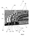
- Figure 1 illustrates a first preferred embodiment of the structural arrangement 10 for an access window 30 to the fuel tank 20 with composite coating 40, which is the object of this invention.
- the access window 30 to the fuel tank 20 is disposed on a structure of the aircraft made of composite material.
- This structure may be the wing of the aircraft or another part which receives a fuel tank 20. Therefore, the coating 40 of the fuel tank 20 in question is made of composite material.
- the access window 30 receives an external metal lid 11 and an internal lid 14 made of composite material.
- the continuous metal frame 31 is fastened to the composite coating 40 of the fuel tank 20 by way of fastening elements 32. More specifically, the continuous metal frame 31 comprises a first fastening portion 311 fastenably disposed on the composite coating 40 and a second protection portion 312 against mechanical damage, perpendicular to the first fastening portion 311, disposed perimetrally on the access window 30 to the fuel tank 20.
- the continuous metal frame 31 provides a continuous contour on the edges of the access window 30 by way of the second protection portion 312, and a continuous contour inside the fuel tank 20, on the composite coating 40 by way of the first fastening portion 311, as can be seen in figures 2A, 2B , 3A and 3B .
- the first fastening portion 311 and the second protection portion 312 form a continuous metal frame 31 in a single part.
- the fastening elements 32 are made of metal and may consist of screws, pins, rivets or other equivalent elements, provided they are made of metal and are capable of fastening with safety and reliability, the continuous metal frame 31 on the composite coating 40.
- a first layer of insulating material 21 Between the first fastening portion 311 of the continuous metal frame 31 and the composite coating 40 there is disposed a first layer of insulating material 21.
- the purpose of this layer of insulating material 21 is to insulate electrically the internal portion of the fuel tank 20.
- the insulating material 21 used can be made of any material already commercialized, as long as it electrically insulates the inside of the tank 20 fully and reliably.
- the second protection portion 312 of the continuous metal frame 31 comprises a first support surface 313 disposed in the internal portion of the fuel tank 20 and is endowed with a sealing ring 19.
- the function of the sealing ring 19 is to prevent fuel leakage through the access window 30.
- the internal lid 14 which is made of composite material, is associated to the external metal lid 11 forming a double lid.
- the internal lid 14 comprises a perimeter 15 which is supported on the sealing ring 19 and the flange 16 projecting perpendicularly in relation to the perimeter 15 and towards the external lid 11. Accordingly, by way of the fastening means 12, which consist of self-sealing flange-nuts or other equivalent elements, the internal lid 14 is fastened to the external lid 11 and both supported on the second protection portion 312 of the continuous metal frame 31.
- the perimeter 15 of the internal lid 14 is supported on the sealing ring 19 positioned on the first support surface 313 of the second protection portion 312, while the external lid 11 is supported on the second support surface 314 of the second protection portion 312, opposite the first support surface 313.
- the self-sealing flange-nuts 12 circumvent the perimeter 15 of the internal lid 14 guaranteeing the fastening of the internal 14 and external 11 lids on the continuous metal frame 31.
- a second layer of insulating material 22 Between the flange 16 of the internal lid 14 and the external lid 11 there is disposed a second layer of insulating material 22.
- the function of this second layer of insulating material 22 is to prevent the flow of electric current from the external lid 11 to the internal lid 14 and, accordingly, prevent sparking in the internal portion of the fuel tank 20.
- the insulating material 22 used can be made of any material already commercialized, as long as it electrically insulates the inside of the tank 20 fully and reliably.
- the structural arrangement 10 for an access window 30 to the fuel tank 20 with composite coating 40 as illustrated in figure 1 and described above imposes a flow path for the electric current which prevents the occurrence of sparking in the internal portion of the fuel tank 20.
- the presence of the second layer of insulating material 22 between the external lid 11 which is made of metal and the internal lid 14 which is made of composite prevents the passage of the electric current between these lids and the formation of sparking.
- the positioning of the first layer of insulating material 21 between the first fastening portion 311 of the continuous metal frame 31 and the composite coating 40 prevents the passage of the electric current through these components and the occurrence of sparking.
- the path having least resistance through which the electric current is forced to flow is formed by the external metal lid 11, the continuous metal frame 31 and the fastening elements 32 also made of metal, to the external portion of the coating 40.
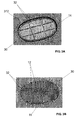
- FIGS 2A and 2B illustrate the access window 30 to the fuel tank 20 containing the structural arrangement 10, according to a first preferred embodiment illustrated in figure 1 , seen from the internal portion of the fuel tank 20.
- the inner edge of the access window 30 is enveloped by the first fastening portion 311 of the continuous metal frame 31 which is supported on the composite coating 40 in the internal portion of the fuel tank 20 while the second protection portion 312 protects the corners or ends of the composite coating 40.
- the structural arrangement 10 prevents physical damage to the structure of the composite coating 40 when it is necessary to withdraw the external 11 and internal 14 lids for inspection or maintenance.
- the presence of the internal lid 14 guarantees a flat surface which does not allow fuel to accumulate at the access window 30.
- FIGS 3A and 3B illustrate the access window 30 to the fuel tank 20 containing the structural arrangement 10, according to a first preferred embodiment illustrated in figure 1 , seen from the external portion of the aircraft. These views reveal that the fastening elements 32 of the continuous metal frame 31 traverse the coating 40 allowing contact with an external portion of the coating 40. For this reason, these metal fastening elements 32 jointly with the continuous metal frame 31 cooperate in the conduction of the electric current to the external environment.
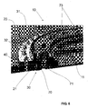
- Figure 4 illustrates a second preferred embodiment of the structural arrangement 10 for an access window 30 to the fuel tank 20 with composite coating 40, which is the object of this invention.
- the access window 30 to the fuel tank 20 is disposed on a structure of the aircraft made of composite material.
- This structure may be the wing of the aircraft or another part which receives a fuel tank 20. Therefore, the coating 40 of the fuel tank 20 in question is made of composite material.
- the continuous metal frame 31 is as described in the first embodiment and, therefore, bears the same characteristics of form and function.
- the fastening elements 32 are also made of metal and may consist of screws, pins, rivets or other equivalent elements, provided they are made of and capable of fastening with safety and reliability, the continuous metal frame 31 on the composite coating 40.
- the insulating material 21 used can be any material already commercialized, as long as it electrically insulates the inside of the tank 20 fully and reliably.
- the second protection portion 312 of the continuous metal frame 31 comprises a first support surface 313 disposed in the internal portion of the fuel tank 20 and endowed with a sealing ring 19.
- the function of the sealing ring 19 is to prevent fuel leakage through the access window 30.
- the external metal lid 11 comprises a perimeter 151 which is supported on the sealing ring 19 positioned on the first support surface 313 of the second protection portion 312, and a recess 18 disposed on a surface opposite that of the perimeter 151.
- This recess 18 is parallel to the second support surface 314 of the second protection portion 312 and continuous along the perimeter of the access window 30.
- a metal fastening ring 70 On a second support surface 314 of the second protection portion 312 and the recess 18 of the external lid 11 there is supported a metal fastening ring 70, whose function is to enable the fastening of the external lid 11 on the continuous metal frame 31 by way of the fastening means 12, which consist of self-sealing flange-nuts or other equivalent elements.
- a conductive web 71 is positioned between the second support surface 314 of the second protection portion 312 and the recess 18 of the external lid 11 and the fastening ring 70.
- the function of this conductive web is to provide a good path for conducting the electric current between the external lid 11 and the continuous metal frame 31.
- the structural arrangement 10 for an access window 30 to the fuel tank 20 with composite coating 40 illustrated in figure 4 imposes a flow path for the electric current which prevents the occurrence of sparking in the internal portion of the fuel tank 20.
- the path of least resistance through which the electric current is forced to flow is formed by the external metal lid 11, the fastening ring 70 with the assistance of the conduction web 71, the continuous metal frame 31 and the fastening elements 32 also made of metal, to the external portion of the coating 40.
- the continuous metal frame 31 provides protection for the edges of the coating 40 during inspection or maintenance.
- Figure 5 illustrates a third preferred embodiment of the structural arrangement 10 for an access window 30 a fuel tank 20 with composite coating 40, which is the object of the present invention.
- the access window 30 to the fuel tank 20 is disposed on a structure of the aircraft made of composite material.
- This structure may be the wing of the aircraft or another part that receives a fuel tank 20. Therefore, the coating 40 of the fuel tank 20 in question is made of composite material.
- the access window 30 only receives the external lid 11 and in this third embodiment, the external lid 11 is made of composite material.
- the form of this external lid 11 made of composite is the same as the external metal lid 11 of the second preferred embodiment, whereby enabling reliable closure of the access window 30.
- the continuous metal frame 31 is as described in the prior embodiments and, therefore, bears the same characteristics of form and function.
- the fastening elements 32 are also made of metal and may consist of screws, pins, rivets or other equivalent elements, provided they are made of metal and capable of fastening with safety and reliability, the continuous metal frame 31 on the composite coating 40.
- the external lid 11 made of composite comprises a perimeter 151 which is supported on the sealing ring 19 positioned on the first support surface 313 of the second protection portion 312, and a recess 18 disposed on a surface opposite that of the perimeter 151.
- This recess 18 is parallel to the second support surface 314 of the second protection portion 312 and continuous along the perimeter of the access window 30.
- a metal fastening ring 70 On the second support surface 314 of the second protection portion 312 and the recess 18 of the external lid 11 there is supported a metal fastening ring 70, whose function is to allow the fastening of the external lid 11 made of composite on the continuous metal frame 31 by way of the fastening means 12, which consist of self-sealing flange-nuts or other equivalent elements.
- a conductive web 71 is positioned between the second support surface 314 of the second protection portion 312 and the recess 18 of the lid 11 made of composite and the fastening ring 70.
- this conductive web is to provide a good path for conducting the electric current between the external lid 11 and the continuous metal frame.
- a layer of insulating material 21 is disposed between the first fastening portion 311 of the continuous metal frame 31 and the composite coating 40 and there is also a layer of insulating material 21 between the side wall of the perimeter 151 of the external lid 11 and the continuous metal frame 31 wherein this layer of insulating material 21 also extends between the support surface 313 of the metal frame 31 and the lower portion of the perimeter 151 of the lid 11. This prevents the passage of the electric current of the external lid 11 to the continuous metal frame 31, whereby preventing the occurrence of sparking on this interface.
- the path of least resistance through which the electric current is forced to flow is formed by the external lid 11 made of composite, the fastening ring 70 with the assistance of the conduction web 71, the continuous metal frame 31 and the fastening elements 32 also made of metal, to the external portion of the coating 40.
- Figure 6 illustrates a fourth preferred embodiment of the structural arrangement 10 for an access window 30 to the fuel tank 20 with composite coating 40, which is the object of the present invention.
- the external lid 11 is made of metal and the other components are as described in the second preferred embodiment illustrated in figure 4 .
- the difference in this fourth embodiment in relation to the second embodiment is the fact that the self-sealing flange-nuts 12 which fasten the external lid 11 are replaced by threaded inserts 73 on the external lid 11 itself ( figure 6 ).
- Figure 7 illustrates a fifth preferred embodiment of the structural arrangement 10 for an access window 30 to the fuel tank 20 having composite coating 40, which is the object of the present invention.
- the external lid 11 is made of composite material and the other components are as described in the third preferred embodiment illustrated in figure 5 .
- the difference in this fifth embodiment in relation to the third embodiment is the fact that the self-sealing flange-nuts 12 which fasten the external lid 11 are replaced by threaded inserts 73 on the external lid 11 itself ( figure 7 ).
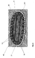
- Figure 8 illustrates a second or third preferred embodiment of the structural arrangement 10 for an access window 30 to the fuel tank 20 with composite coating 40 seen from the internal portion of the fuel tank 20.
- the inner edge of the access window 30 is enveloped by the first fastening portion 311 of the continuous metal frame 31 which is supported on the composite coating 40 in the internal portion of the fuel tank 20 while the second protection portion 312 protects the corners or ends of the composite coating 40.
- the structural arrangement 10 prevents damage to the composite coating 40 when it is necessary to withdraw the external lid 11 for maintenance or inspection.
- the inner surface of the external lid 11 is the same, with the exception of the regions which form the threaded inserts 73, the difference being that the self-sealing flange-nuts are replaced by these threaded inserts 73 formed on the external lid 11 itself.
- the structural arrangement 10 prevents the occurrence of sparking in the internal portion of the fuel tank 20 and decreases the accumulation of fuel at the access window 30 (in the case of the first preferred embodiment) and also provides protection against physical damage to the edge of the composite coating 40.
Landscapes
- Engineering & Computer Science (AREA)
- Aviation & Aerospace Engineering (AREA)
- Mechanical Engineering (AREA)
- Civil Engineering (AREA)
- Structural Engineering (AREA)
- Cooling, Air Intake And Gas Exhaust, And Fuel Tank Arrangements In Propulsion Units (AREA)
Applications Claiming Priority (1)
| Application Number | Priority Date | Filing Date | Title |
|---|---|---|---|
| BRPI1105342-9A BRPI1105342B1 (pt) | 2011-12-28 | 2011-12-28 | arranjo estrutural para janela de acesso a tanque de combustível com revestimento em compósito |
Publications (3)
| Publication Number | Publication Date |
|---|---|
| EP2610167A2 true EP2610167A2 (de) | 2013-07-03 |
| EP2610167A3 EP2610167A3 (de) | 2017-09-06 |
| EP2610167B1 EP2610167B1 (de) | 2020-01-22 |
Family
ID=47678530
Family Applications (1)
| Application Number | Title | Priority Date | Filing Date |
|---|---|---|---|
| EP12199685.4A Active EP2610167B1 (de) | 2011-12-28 | 2012-12-28 | Strukturanordnung für eine Zugangsabdeckung für einen Kraftstofftank mit Verbundstoffbeschichtung |
Country Status (4)
| Country | Link |
|---|---|
| US (1) | US9194174B2 (de) |
| EP (1) | EP2610167B1 (de) |
| CN (1) | CN103183129B (de) |
| BR (1) | BRPI1105342B1 (de) |
Families Citing this family (6)
| Publication number | Priority date | Publication date | Assignee | Title |
|---|---|---|---|---|
| BRPI1105342B1 (pt) * | 2011-12-28 | 2020-12-01 | Embraer S.A. | arranjo estrutural para janela de acesso a tanque de combustível com revestimento em compósito |
| EP2664547B1 (de) * | 2012-05-16 | 2016-04-06 | Airbus Operations, S.L. | Abdeckung für äußeren Kraftstofftankzugang, Flügel und Flugzeug |
| FR3043062B1 (fr) | 2015-10-28 | 2017-11-24 | Aviacomp | Porte d'acces au reservoir de carburant ou a une zone seche d'un aeronef |
| JP6734918B2 (ja) * | 2016-04-28 | 2020-08-05 | ギガフォトン株式会社 | タンク、ターゲット生成装置、及び、極端紫外光生成装置 |
| CN109398727B (zh) * | 2017-08-15 | 2023-08-04 | 中航贵州飞机有限责任公司 | 一种可拆卸口盖密封装配的方法 |
| JP7210248B2 (ja) * | 2018-11-30 | 2023-01-23 | 三菱重工業株式会社 | パネル構造体及び航空機 |
Citations (2)
| Publication number | Priority date | Publication date | Assignee | Title |
|---|---|---|---|---|
| US20090166473A1 (en) | 2007-12-27 | 2009-07-02 | Airbus Espana, S.L. | Optimized aircraft manhole |
| US7576966B2 (en) | 2006-02-23 | 2009-08-18 | The Boeing Company | Method and system for electrical bonding of fuel tank penetrations |
Family Cites Families (14)
| Publication number | Priority date | Publication date | Assignee | Title |
|---|---|---|---|---|
| US2635785A (en) * | 1951-10-30 | 1953-04-21 | Rohr Aircraft Corp | Sealed door assembly |
| US4428867A (en) * | 1981-11-02 | 1984-01-31 | Lockheed Corporation | Electrically conductive structural adhesive |
| US4530443A (en) * | 1983-11-10 | 1985-07-23 | The Boeing Company | Unitary access panel for aircraft fuel tanks |
| US4579248A (en) * | 1983-11-10 | 1986-04-01 | The Boeing Company | Access panel assembly for aircraft fuel tank |
| US5316167A (en) * | 1992-12-23 | 1994-05-31 | United Technologies Corporation | Pressure resistant fuel tank closure |
| US20110250626A1 (en) * | 2002-09-09 | 2011-10-13 | Reactive Surfaces, Ltd. | Visual Assays for Coatings Incorporating Bioactive Enzymes for Catalytic Functions |
| US20050281999A1 (en) * | 2003-03-12 | 2005-12-22 | Petritech, Inc. | Structural and other composite materials and methods for making same |
| US7898785B2 (en) * | 2006-12-07 | 2011-03-01 | The Boeing Company | Lightning protection system for an aircraft composite structure |
| ES2335837B1 (es) * | 2007-06-29 | 2011-02-18 | Airbus España, Sl. | Cubierta para boca de acceso de aeronave. |
| US8443575B1 (en) * | 2009-10-27 | 2013-05-21 | The Boeing Company | Composite access door |
| JP5378260B2 (ja) * | 2010-02-10 | 2013-12-25 | 三菱航空機株式会社 | 開口部の閉塞部材、航空機 |
| US8422192B2 (en) * | 2011-07-29 | 2013-04-16 | Airbus Operations Limited | Fuel pipe joint on an aircraft |
| BRPI1105342B1 (pt) * | 2011-12-28 | 2020-12-01 | Embraer S.A. | arranjo estrutural para janela de acesso a tanque de combustível com revestimento em compósito |
| US9079656B2 (en) * | 2013-02-14 | 2015-07-14 | The Boeing Company | Mistake resistant design for wing fuel tank access door alignment features |
-
2011
- 2011-12-28 BR BRPI1105342-9A patent/BRPI1105342B1/pt not_active IP Right Cessation
-
2012
- 2012-12-28 CN CN201210587474.1A patent/CN103183129B/zh not_active Expired - Fee Related
- 2012-12-28 US US13/729,416 patent/US9194174B2/en not_active Expired - Fee Related
- 2012-12-28 EP EP12199685.4A patent/EP2610167B1/de active Active
Patent Citations (2)
| Publication number | Priority date | Publication date | Assignee | Title |
|---|---|---|---|---|
| US7576966B2 (en) | 2006-02-23 | 2009-08-18 | The Boeing Company | Method and system for electrical bonding of fuel tank penetrations |
| US20090166473A1 (en) | 2007-12-27 | 2009-07-02 | Airbus Espana, S.L. | Optimized aircraft manhole |
Also Published As
| Publication number | Publication date |
|---|---|
| CN103183129B (zh) | 2017-06-06 |
| EP2610167A3 (de) | 2017-09-06 |
| US9194174B2 (en) | 2015-11-24 |
| US20130205667A1 (en) | 2013-08-15 |
| EP2610167B1 (de) | 2020-01-22 |
| BRPI1105342B1 (pt) | 2020-12-01 |
| BRPI1105342A2 (pt) | 2013-11-05 |
| CN103183129A (zh) | 2013-07-03 |
Similar Documents
| Publication | Publication Date | Title |
|---|---|---|
| US9194174B2 (en) | Structural arrangement for access window to fuel tank with composite coating | |
| US8141820B2 (en) | Optimized aircraft manhole | |
| EP2962933B1 (de) | Schliesselement für eine öffnung | |
| EP1628879B1 (de) | Verbundstruktur-blitzschlagschutz | |
| KR102552511B1 (ko) | 차량용 후방구조 | |
| EP2441678B1 (de) | Blitzschlagschutz für Flugzeuge | |
| US9505482B2 (en) | Facing arrangement and aircraft or spacecraft | |
| EP3216693A1 (de) | Aerodynamische fläche eines flugzeugs mit abnehmbarer vorderkante | |
| US20210280383A1 (en) | Fuse box for battery of vehicle | |
| US20160244182A1 (en) | Structure for aircraft, method of manufacturing structure for aircraft and method of making design information of structure for aircraft | |
| US9016615B2 (en) | Lightning and corrosion protection arrangement in an aircraft structural component | |
| EP2686244B1 (de) | Elektrisches masseverbindungs-netzwerk für ein flugzeug | |
| EP3835038A1 (de) | Hinterkante für eine zusammengesetzte mehrholm-hubfläche und verfahren zur herstellung dieser hinterkante | |
| EP2535264B1 (de) | Verschlusselement zum öffnen | |
| CN110254687B (zh) | 复合材料结构体、航空器及雷电流的诱导方法 | |
| CN209880678U (zh) | 电池包及其箱体 | |
| GB2201737A (en) | Lightning strike protection gasket | |
| CN109812201A (zh) | 屏蔽门系统的立柱结构、门体结构及屏蔽门系统 | |
| EP3270673B1 (de) | Geformtes kartenführungsleisten-chassis |
Legal Events
| Date | Code | Title | Description |
|---|---|---|---|
| PUAI | Public reference made under article 153(3) epc to a published international application that has entered the european phase |
Free format text: ORIGINAL CODE: 0009012 |
|
| 17P | Request for examination filed |
Effective date: 20130123 |
|
| AK | Designated contracting states |
Kind code of ref document: A2 Designated state(s): AL AT BE BG CH CY CZ DE DK EE ES FI FR GB GR HR HU IE IS IT LI LT LU LV MC MK MT NL NO PL PT RO RS SE SI SK SM TR |
|
| AX | Request for extension of the european patent |
Extension state: BA ME |
|
| PUAL | Search report despatched |
Free format text: ORIGINAL CODE: 0009013 |
|
| AK | Designated contracting states |
Kind code of ref document: A3 Designated state(s): AL AT BE BG CH CY CZ DE DK EE ES FI FR GB GR HR HU IE IS IT LI LT LU LV MC MK MT NL NO PL PT RO RS SE SI SK SM TR |
|
| AX | Request for extension of the european patent |
Extension state: BA ME |
|
| RIC1 | Information provided on ipc code assigned before grant |
Ipc: B64C 3/34 20060101AFI20170802BHEP Ipc: B64D 37/32 20060101ALI20170802BHEP Ipc: B64D 37/02 20060101ALI20170802BHEP |
|
| STAA | Information on the status of an ep patent application or granted ep patent |
Free format text: STATUS: EXAMINATION IS IN PROGRESS |
|
| 17Q | First examination report despatched |
Effective date: 20190510 |
|
| GRAP | Despatch of communication of intention to grant a patent |
Free format text: ORIGINAL CODE: EPIDOSNIGR1 |
|
| STAA | Information on the status of an ep patent application or granted ep patent |
Free format text: STATUS: GRANT OF PATENT IS INTENDED |
|
| INTG | Intention to grant announced |
Effective date: 20190829 |
|
| GRAS | Grant fee paid |
Free format text: ORIGINAL CODE: EPIDOSNIGR3 |
|
| GRAA | (expected) grant |
Free format text: ORIGINAL CODE: 0009210 |
|
| STAA | Information on the status of an ep patent application or granted ep patent |
Free format text: STATUS: THE PATENT HAS BEEN GRANTED |
|
| AK | Designated contracting states |
Kind code of ref document: B1 Designated state(s): AL AT BE BG CH CY CZ DE DK EE ES FI FR GB GR HR HU IE IS IT LI LT LU LV MC MK MT NL NO PL PT RO RS SE SI SK SM TR |
|
| REG | Reference to a national code |
Ref country code: GB Ref legal event code: FG4D |
|
| REG | Reference to a national code |
Ref country code: CH Ref legal event code: EP |
|
| REG | Reference to a national code |
Ref country code: AT Ref legal event code: REF Ref document number: 1226758 Country of ref document: AT Kind code of ref document: T Effective date: 20200215 |
|
| REG | Reference to a national code |
Ref country code: IE Ref legal event code: FG4D |
|
| REG | Reference to a national code |
Ref country code: DE Ref legal event code: R096 Ref document number: 602012067386 Country of ref document: DE |
|
| REG | Reference to a national code |
Ref country code: NL Ref legal event code: MP Effective date: 20200122 |
|
| REG | Reference to a national code |
Ref country code: LT Ref legal event code: MG4D |
|
| PG25 | Lapsed in a contracting state [announced via postgrant information from national office to epo] |
Ref country code: PT Free format text: LAPSE BECAUSE OF FAILURE TO SUBMIT A TRANSLATION OF THE DESCRIPTION OR TO PAY THE FEE WITHIN THE PRESCRIBED TIME-LIMIT Effective date: 20200614 Ref country code: FI Free format text: LAPSE BECAUSE OF FAILURE TO SUBMIT A TRANSLATION OF THE DESCRIPTION OR TO PAY THE FEE WITHIN THE PRESCRIBED TIME-LIMIT Effective date: 20200122 Ref country code: NL Free format text: LAPSE BECAUSE OF FAILURE TO SUBMIT A TRANSLATION OF THE DESCRIPTION OR TO PAY THE FEE WITHIN THE PRESCRIBED TIME-LIMIT Effective date: 20200122 Ref country code: RS Free format text: LAPSE BECAUSE OF FAILURE TO SUBMIT A TRANSLATION OF THE DESCRIPTION OR TO PAY THE FEE WITHIN THE PRESCRIBED TIME-LIMIT Effective date: 20200122 Ref country code: NO Free format text: LAPSE BECAUSE OF FAILURE TO SUBMIT A TRANSLATION OF THE DESCRIPTION OR TO PAY THE FEE WITHIN THE PRESCRIBED TIME-LIMIT Effective date: 20200422 |
|
| PG25 | Lapsed in a contracting state [announced via postgrant information from national office to epo] |
Ref country code: BG Free format text: LAPSE BECAUSE OF FAILURE TO SUBMIT A TRANSLATION OF THE DESCRIPTION OR TO PAY THE FEE WITHIN THE PRESCRIBED TIME-LIMIT Effective date: 20200422 Ref country code: LV Free format text: LAPSE BECAUSE OF FAILURE TO SUBMIT A TRANSLATION OF THE DESCRIPTION OR TO PAY THE FEE WITHIN THE PRESCRIBED TIME-LIMIT Effective date: 20200122 Ref country code: SE Free format text: LAPSE BECAUSE OF FAILURE TO SUBMIT A TRANSLATION OF THE DESCRIPTION OR TO PAY THE FEE WITHIN THE PRESCRIBED TIME-LIMIT Effective date: 20200122 Ref country code: HR Free format text: LAPSE BECAUSE OF FAILURE TO SUBMIT A TRANSLATION OF THE DESCRIPTION OR TO PAY THE FEE WITHIN THE PRESCRIBED TIME-LIMIT Effective date: 20200122 Ref country code: GR Free format text: LAPSE BECAUSE OF FAILURE TO SUBMIT A TRANSLATION OF THE DESCRIPTION OR TO PAY THE FEE WITHIN THE PRESCRIBED TIME-LIMIT Effective date: 20200423 Ref country code: IS Free format text: LAPSE BECAUSE OF FAILURE TO SUBMIT A TRANSLATION OF THE DESCRIPTION OR TO PAY THE FEE WITHIN THE PRESCRIBED TIME-LIMIT Effective date: 20200522 |
|
| REG | Reference to a national code |
Ref country code: DE Ref legal event code: R097 Ref document number: 602012067386 Country of ref document: DE |
|
| PG25 | Lapsed in a contracting state [announced via postgrant information from national office to epo] |
Ref country code: SM Free format text: LAPSE BECAUSE OF FAILURE TO SUBMIT A TRANSLATION OF THE DESCRIPTION OR TO PAY THE FEE WITHIN THE PRESCRIBED TIME-LIMIT Effective date: 20200122 Ref country code: SK Free format text: LAPSE BECAUSE OF FAILURE TO SUBMIT A TRANSLATION OF THE DESCRIPTION OR TO PAY THE FEE WITHIN THE PRESCRIBED TIME-LIMIT Effective date: 20200122 Ref country code: RO Free format text: LAPSE BECAUSE OF FAILURE TO SUBMIT A TRANSLATION OF THE DESCRIPTION OR TO PAY THE FEE WITHIN THE PRESCRIBED TIME-LIMIT Effective date: 20200122 Ref country code: ES Free format text: LAPSE BECAUSE OF FAILURE TO SUBMIT A TRANSLATION OF THE DESCRIPTION OR TO PAY THE FEE WITHIN THE PRESCRIBED TIME-LIMIT Effective date: 20200122 Ref country code: CZ Free format text: LAPSE BECAUSE OF FAILURE TO SUBMIT A TRANSLATION OF THE DESCRIPTION OR TO PAY THE FEE WITHIN THE PRESCRIBED TIME-LIMIT Effective date: 20200122 Ref country code: LT Free format text: LAPSE BECAUSE OF FAILURE TO SUBMIT A TRANSLATION OF THE DESCRIPTION OR TO PAY THE FEE WITHIN THE PRESCRIBED TIME-LIMIT Effective date: 20200122 Ref country code: EE Free format text: LAPSE BECAUSE OF FAILURE TO SUBMIT A TRANSLATION OF THE DESCRIPTION OR TO PAY THE FEE WITHIN THE PRESCRIBED TIME-LIMIT Effective date: 20200122 Ref country code: DK Free format text: LAPSE BECAUSE OF FAILURE TO SUBMIT A TRANSLATION OF THE DESCRIPTION OR TO PAY THE FEE WITHIN THE PRESCRIBED TIME-LIMIT Effective date: 20200122 |
|
| REG | Reference to a national code |
Ref country code: AT Ref legal event code: MK05 Ref document number: 1226758 Country of ref document: AT Kind code of ref document: T Effective date: 20200122 |
|
| PLBE | No opposition filed within time limit |
Free format text: ORIGINAL CODE: 0009261 |
|
| STAA | Information on the status of an ep patent application or granted ep patent |
Free format text: STATUS: NO OPPOSITION FILED WITHIN TIME LIMIT |
|
| 26N | No opposition filed |
Effective date: 20201023 |
|
| PG25 | Lapsed in a contracting state [announced via postgrant information from national office to epo] |
Ref country code: AT Free format text: LAPSE BECAUSE OF FAILURE TO SUBMIT A TRANSLATION OF THE DESCRIPTION OR TO PAY THE FEE WITHIN THE PRESCRIBED TIME-LIMIT Effective date: 20200122 Ref country code: IT Free format text: LAPSE BECAUSE OF FAILURE TO SUBMIT A TRANSLATION OF THE DESCRIPTION OR TO PAY THE FEE WITHIN THE PRESCRIBED TIME-LIMIT Effective date: 20200122 |
|
| PG25 | Lapsed in a contracting state [announced via postgrant information from national office to epo] |
Ref country code: PL Free format text: LAPSE BECAUSE OF FAILURE TO SUBMIT A TRANSLATION OF THE DESCRIPTION OR TO PAY THE FEE WITHIN THE PRESCRIBED TIME-LIMIT Effective date: 20200122 Ref country code: SI Free format text: LAPSE BECAUSE OF FAILURE TO SUBMIT A TRANSLATION OF THE DESCRIPTION OR TO PAY THE FEE WITHIN THE PRESCRIBED TIME-LIMIT Effective date: 20200122 |
|
| REG | Reference to a national code |
Ref country code: DE Ref legal event code: R119 Ref document number: 602012067386 Country of ref document: DE |
|
| REG | Reference to a national code |
Ref country code: CH Ref legal event code: PL |
|
| GBPC | Gb: european patent ceased through non-payment of renewal fee |
Effective date: 20201228 |
|
| PG25 | Lapsed in a contracting state [announced via postgrant information from national office to epo] |
Ref country code: MC Free format text: LAPSE BECAUSE OF FAILURE TO SUBMIT A TRANSLATION OF THE DESCRIPTION OR TO PAY THE FEE WITHIN THE PRESCRIBED TIME-LIMIT Effective date: 20200122 |
|
| REG | Reference to a national code |
Ref country code: BE Ref legal event code: MM Effective date: 20201231 |
|
| PG25 | Lapsed in a contracting state [announced via postgrant information from national office to epo] |
Ref country code: IE Free format text: LAPSE BECAUSE OF NON-PAYMENT OF DUE FEES Effective date: 20201228 Ref country code: LU Free format text: LAPSE BECAUSE OF NON-PAYMENT OF DUE FEES Effective date: 20201228 |
|
| PG25 | Lapsed in a contracting state [announced via postgrant information from national office to epo] |
Ref country code: LI Free format text: LAPSE BECAUSE OF NON-PAYMENT OF DUE FEES Effective date: 20201231 Ref country code: GB Free format text: LAPSE BECAUSE OF NON-PAYMENT OF DUE FEES Effective date: 20201228 Ref country code: DE Free format text: LAPSE BECAUSE OF NON-PAYMENT OF DUE FEES Effective date: 20210701 Ref country code: CH Free format text: LAPSE BECAUSE OF NON-PAYMENT OF DUE FEES Effective date: 20201231 |
|
| PG25 | Lapsed in a contracting state [announced via postgrant information from national office to epo] |
Ref country code: TR Free format text: LAPSE BECAUSE OF FAILURE TO SUBMIT A TRANSLATION OF THE DESCRIPTION OR TO PAY THE FEE WITHIN THE PRESCRIBED TIME-LIMIT Effective date: 20200122 Ref country code: MT Free format text: LAPSE BECAUSE OF FAILURE TO SUBMIT A TRANSLATION OF THE DESCRIPTION OR TO PAY THE FEE WITHIN THE PRESCRIBED TIME-LIMIT Effective date: 20200122 Ref country code: CY Free format text: LAPSE BECAUSE OF FAILURE TO SUBMIT A TRANSLATION OF THE DESCRIPTION OR TO PAY THE FEE WITHIN THE PRESCRIBED TIME-LIMIT Effective date: 20200122 |
|
| PG25 | Lapsed in a contracting state [announced via postgrant information from national office to epo] |
Ref country code: MK Free format text: LAPSE BECAUSE OF FAILURE TO SUBMIT A TRANSLATION OF THE DESCRIPTION OR TO PAY THE FEE WITHIN THE PRESCRIBED TIME-LIMIT Effective date: 20200122 Ref country code: AL Free format text: LAPSE BECAUSE OF FAILURE TO SUBMIT A TRANSLATION OF THE DESCRIPTION OR TO PAY THE FEE WITHIN THE PRESCRIBED TIME-LIMIT Effective date: 20200122 |
|
| PG25 | Lapsed in a contracting state [announced via postgrant information from national office to epo] |
Ref country code: BE Free format text: LAPSE BECAUSE OF NON-PAYMENT OF DUE FEES Effective date: 20201231 |
|
| PGFP | Annual fee paid to national office [announced via postgrant information from national office to epo] |
Ref country code: FR Payment date: 20221208 Year of fee payment: 11 |
|
| PG25 | Lapsed in a contracting state [announced via postgrant information from national office to epo] |
Ref country code: FR Free format text: LAPSE BECAUSE OF NON-PAYMENT OF DUE FEES Effective date: 20231231 |
|
| PG25 | Lapsed in a contracting state [announced via postgrant information from national office to epo] |
Ref country code: FR Free format text: LAPSE BECAUSE OF NON-PAYMENT OF DUE FEES Effective date: 20231231 |