EP2610204A2 - Bewegungskontrolle einer Aufzugskabine - Google Patents
Bewegungskontrolle einer Aufzugskabine Download PDFInfo
- Publication number
- EP2610204A2 EP2610204A2 EP12199501.3A EP12199501A EP2610204A2 EP 2610204 A2 EP2610204 A2 EP 2610204A2 EP 12199501 A EP12199501 A EP 12199501A EP 2610204 A2 EP2610204 A2 EP 2610204A2
- Authority
- EP
- European Patent Office
- Prior art keywords
- value
- values
- signal
- mode
- cabin
- Prior art date
- Legal status (The legal status is an assumption and is not a legal conclusion. Google has not performed a legal analysis and makes no representation as to the accuracy of the status listed.)
- Withdrawn
Links
- 230000033001 locomotion Effects 0.000 title claims abstract description 25
- 230000000903 blocking effect Effects 0.000 claims abstract description 53
- 238000000034 method Methods 0.000 claims abstract description 33
- 238000001514 detection method Methods 0.000 claims abstract description 17
- 238000006243 chemical reaction Methods 0.000 claims abstract description 4
- 238000012545 processing Methods 0.000 claims description 38
- 230000005540 biological transmission Effects 0.000 claims description 7
- 238000012544 monitoring process Methods 0.000 abstract 1
- 238000012360 testing method Methods 0.000 description 15
- 238000012423 maintenance Methods 0.000 description 8
- 238000004891 communication Methods 0.000 description 4
- 230000006870 function Effects 0.000 description 4
- 230000005355 Hall effect Effects 0.000 description 3
- 238000013459 approach Methods 0.000 description 3
- 238000006073 displacement reaction Methods 0.000 description 3
- 238000013475 authorization Methods 0.000 description 2
- 238000004364 calculation method Methods 0.000 description 2
- 230000008859 change Effects 0.000 description 2
- 208000012661 Dyskinesia Diseases 0.000 description 1
- 241001080024 Telles Species 0.000 description 1
- 230000009471 action Effects 0.000 description 1
- 230000008901 benefit Effects 0.000 description 1
- 238000004590 computer program Methods 0.000 description 1
- 230000005611 electricity Effects 0.000 description 1
- 229940082150 encore Drugs 0.000 description 1
- 230000005484 gravity Effects 0.000 description 1
- 238000009434 installation Methods 0.000 description 1
- 238000005259 measurement Methods 0.000 description 1
- 230000008569 process Effects 0.000 description 1
- 230000000717 retained effect Effects 0.000 description 1
Images


Classifications
-
- B—PERFORMING OPERATIONS; TRANSPORTING
- B66—HOISTING; LIFTING; HAULING
- B66B—ELEVATORS; ESCALATORS OR MOVING WALKWAYS
- B66B5/00—Applications of checking, fault-correcting, or safety devices in elevators
- B66B5/0006—Monitoring devices or performance analysers
- B66B5/0018—Devices monitoring the operating condition of the elevator system
- B66B5/0031—Devices monitoring the operating condition of the elevator system for safety reasons
Definitions
- the invention relates to controlling the movement of an elevator car.
- the lifts are generally equipped with a locking device, for example a parachute, able to stop the elevator car in case of fall in the sheath, more generally in case of displacement of the cabin overspeed.
- a locking device for example a parachute
- Existing elevator systems include a speed limiter, equipped with a feeder and springs.
- the limiters are arranged so as to be able to change state when a wheel secured to a pulley of the cable of the elevator system exceeds a certain speed of rotation. In the event of a change of state, the speed limiter blocks this wheel or pulley. The cable thus retained engages the parachute device which blocks the cabin on a guide.
- These gravity and spring sensors may, over time, be slightly out of adjustment.
- position values from a position sensor are received.
- the received values can be relatively reliable and in particular they can be absolute position values.
- the received position values can directly indicate a position, or allow to determine a position after treatment.
- Some elevator systems are equipped with a position sensor in communication with a control cabinet.
- the control cabinet comprises processing means, for example a processor, able to control the movements of the cabin according to user requests and according to the position values received.
- the invention can thus simplify elevator installations in that the position sensor is also in communication with a safety device capable of generating a blockage of the car.
- the locking device of the cabin in the duct may for example be arranged to lock the elevator car on a guide. It may for example be a parachute device, of the type known from the prior art, but controlled by a coil fed by the blocking signal.
- the position sensor comprises means for reading a magnetic tape installed on at least one part and advantageously the entire stroke of the elevator car, such a Hall effect sensor is for example described in FIG. the documents US2006 / 07181 , WO 03/011733 and EP1189034 .
- the invention is in no way limited to this type of sensor.
- a position sensor comprising means for transmitting / receiving laser beams.
- the signal can be sent directly to the blocking device.
- the signal may for example be sent to electromechanical conversion means, for example a coil, a motor or the like, arranged to act directly on the locking device.
- electromechanical conversion means for example a coil, a motor or the like, arranged to act directly on the locking device.
- the invention is in no way limited by a direct control of the locking device.
- the elevator system then comprises this limiter wheel, the cable and a parachute type locking device.
- the overspeed detection is not performed by the limiter, but from the received position values.
- a step of comparing a received position value with a position value corresponding to a limit switch can be provided. If the difference between these two position values is less than a threshold, a stop signal can be sent to the motor.
- this method makes it possible to detect the limit switches, and to make sure of the stopping of the elevator car, when this cabin is approaching the ceiling of the duct or the bottom of the duct.
- it can be provided to receive a variable value indicating a current operating mode of the elevator system.
- the position value corresponding to a limit switch can advantageously and non-limitatively be chosen as a function of the value of this mode variable.
- end position values may be stored in memory so as to associate each end position value with a corresponding mode variable value, each of said mode variable values corresponding to a mode of operation of the system. 'elevator.
- the position value corresponding to a limit switch in case of normal use of the elevator car may be higher than a limit value corresponding to a revision mode of the elevator car.
- This end-of-travel value in the overhaul mode can for example be one meter or two meters lower than the end-of-travel value of the normal mode, since in the event of a revision of the elevator system, a technician is likely to to be above the cabin, in the sheath.
- the plurality of mode variable values comprise a first value corresponding to a normal mode of use of the elevator system and a second value corresponding to a revision mode of the elevator system.
- the end position value associated with the first value may correspond to a limit switch beyond the end of travel corresponding to the position value associated with the second value.
- position values corresponding to a high end of travel for example 5000 mm in normal mode, 4 100 mm in revision mode, and 4500 mm in reduced reserve mode.
- the position values corresponding to a low end-of-travel can be equal to 0 for these three modes, or else at different values. These values are distances relative to the bottom of the sheath, a value corresponding to the bottom of the elevator shaft.
- a similar security can also be implemented when the memorized value corresponds to the maintenance mode, or not.
- This usage mode variable value may be the variable value described above or another value.
- the speed threshold in normal mode, can be relatively high.
- the cab In maintenance mode, the cab is assumed to have much slower movements, so that the speed threshold may be chosen lower.
- the speed of the car is particularly low, and the speed threshold may be chosen even lower.
- the invention can make it possible to choose speed thresholds for the overspeed detection adapted to the current operation of the elevator system, unlike the systems based on weights and springs of the prior art.
- the target position can for example be received from a cabinet of control or processing means integrated into the cabin or other. This may be a destination position of the cabin.
- This method can allow the blocking of the cabin so as to avoid that the target is reached with a speed too different from 0, for example 1 meter / second.
- the method may for example comprise a step of calculating a deceleration value to be applied corresponding to a normal stop, that is to say with a speed equal to a maximum threshold, when the position of the car is the target position . If it turns out that the calculated deceleration is greater than a deceleration threshold, then the blocking signal is emitted.
- This method can thus limit the uncontrolled movements of the cabin when the door is open, and therefore meet the new standards in the field.
- the methods described above can be implemented by digital processing means, for example one or more processor (s).
- This device can make it possible to implement the method described above.
- Each of these devices can comprise or be integrated into one or more processors, for example microcontrollers, microprocessors, DSPs (Digital Signal Processing), FPGAs (Field Programmable Gate Array). ”) Or other.
- processors for example microcontrollers, microprocessors, DSPs (Digital Signal Processing), FPGAs (Field Programmable Gate Array). ”) Or other.
- the device can be integrated in a processor further comprising the sensor of position.
- first processing means may make it possible to determine the position values and, from these position values, to calculate a speed value
- second processing means may allow the detection of overspeed situations, and the generating a blocking signal.
- the speed is determined within the second processing means.
- a system for controlling the movement of a cabin comprising at least the devices described above, as well as the cabin locking device and / or the position sensor.
- an elevator system comprising the control system described above, as well as an elevator car, a guide, a counterweight, a motor, a control cabinet, and / or other.
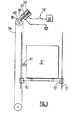
- FIG. 1 an elevator system 1 comprising an elevator car 5 capable of moving vertically from floor to floor in a sheath 3 of a building equipped.
- the sheath 3 comprises a bottom 31 and a ceiling 21.
- This cabin 5 is guided in a conventional manner on guides or vertical rails 7.
- the elevator system may comprise unrepresented elements, such as pulley, motor, counterweight, control cabinet, and / or other.
- a position sensor 10 comprises unrepresented reading means, for example a read head, able to extract data from a magnetic tape 15 installed over substantially the entire stroke of the elevator car.
- the sensor 10 may for example be a Hall effect sensor as described in the document US2006 / 07181 .
- the invention is not limited to a positioning of the sensor 10 below the cabin 5, as shown in FIG. figure 1 .
- the sensor 10 is connected by one or more wires shown here schematically by a single wire referenced 12, to processing means 9.
- the position sensor 10 can thus transmit to the processing means 9 the data read from the magnetic tape 15 for example, position values of the elevator car, or even data for determining position values.
- the invention is not limited to a positioning of the processing means 9 below the cabin 5, as shown in FIG. figure 1 .
- the processing means 9 are arranged to detect any overspeed from the data received from the position sensor 10.
- These processing means 9 are in communication with a locking device 11.
- wire 13 connect the processing means 9 to the locking device 11.
- the invention is not limited to a positioning of the locking device 11 below the cabin 5, as shown on the figure 1 .
- this device it will be possible to arrange this device above the cabin, or else laterally.
- the invention is not limited by a positioning of the sensor 10, processing means 9 and the locking device in proximity to each other.
- the sensor and the locking device may be located below the cabin, and the processing means above this cabin.
- the locking device may be a parachute device of the type known from the prior art, for example with a movable jaw or the like.
- the processing means 9 may nevertheless be adapted to control other types of locking devices, for example a locking cleat, a parachute with speed limiter, a stop valve, and / or other.
- the elevator system 1 thus comprises a movement control device 8 comprising the processing means 9 as well as data receiving means 12 from the position sensor 10, and also transmission means 13, for, in particular case of overspeed detection by the processing means 9, send a blocking signal to the blocking device 11.
- the processing means 9 may for example comprise or be integrated in a processor, or for example a microcontroller a microprocessor, a DSP, an FPGA or other.
- the device 8 may comprise or be integrated in a processor.
- the receiving means 12 may, for example, comprise input pins, an input port, one or more wires, or the like.
- the transmitting means 13 may comprise an output port, an output pin, one or more wires, the wireless transmission means or the like.
- the receiving means 12 may then comprise means of communication between two parts of the same processor, for example reading buses from a memory internal to the processor.
- control system 14 incorporating the position sensor 10 and the motion control device 8, can be used to control the locking device 11 from read data. on the magnetic tape 15.
- This system 14 can be relatively compact and have a relatively low weight.
- the lift system of the figure 1 is devoid of limiting device, and cable, the overspeed detection being performed by the system 14.
- the elevator system 1 can be more compact than the systems of the prior art.
- the figure 2 describes an example of a method implemented by the processing means referenced 9 on the figure 1 .
- these processing means receive a target position value x target.
- This position value x target may for example be from a control cabinet not shown on the figure 1 , able to program and impose the displacements of the cabin 5 according to the requests of the users and the position values received from the position sensor 10.
- This target target position value X is kept in a memory. This value will be used during a test step 214 described later, in order to avoid reaching the target position with too high a speed.
- This mode variable value Var_mode1 is used to select a position value corresponding to a limit switch x FC , during a step 202.
- the processing means may for example be programmed to choose a value x FC of 10000 mm when the elevator system is used in a normal manner, for traveling purposes. users, 9500 mm in reduced reserve mode, and 9000 mm in revision mode.
- this step is not represented on the figure 2 it may optionally be possible to further choose a low end position value as a function of the value of the variable Var_mode1. For example we can choose a value of 0 mm in normal mode, 500 mm in reduced reserve mode, and 10000 mm in revision mode.
- the processing means comprise a memory associating each potential value of the variable Var_mode2 with a respective speed threshold value V THR .
- V THR can be 50 cm / second.
- the leveling or iso-leveling mode it is possible to choose lower speed thresholds, for example 20 and 10 cm / second respectively.
- a reception step 203 of a current position value x (n) resulting from the Hall effect position sensor in order to select the values of the variables x FC and V THR , a reception step 203 of a current position value x (n) resulting from the Hall effect position sensor.
- the treatment means referenced 9 on the figure 1 are arranged to estimate during a step 204 a speed value of the elevator car from this position value x (n) and from a position value received during a previous cycle x (n -1).
- the processing means 9 may include calculation means capable of estimating a time derivative of the speed. More simply, since the duration of a cycle is relatively constant from one cycle to the next, it will be sufficient to calculate a difference between the value x (n) of the current cycle and the value x (n -1) of the current cycle and consider that this difference is proportional to the actual speed of the cabin.
- the threshold value V THR is itself calculated or converted to be comparable to this difference.
- step 205 the estimated cabin speed V (n) is compared with the speed threshold value chosen in step 202.
- step 204 If the estimated speed value in step 204 is greater than the threshold value V THR , then the processing means 9 transmit to the blocking device 11 a blocking signal.
- the processing means transmit by default a non-zero signal to impose, via a coil system, a position to the blocking device.
- the signal emitted by the processing means 9 is set to zero, so that the coil no longer exerts any action on the locking device, which then blocks the elevator car.
- the emission of this blocking signal is referenced 209 on the figure 2 .
- the blocking signal may simply correspond to a lack of signal, or a signal equal to zero. This is advantageous in that in case of failure in the chain of transmission between the processing means 9 and the parachute 11, for example of cutting a wire connected to the coil, the cabin will be blocked, so that the failure can be detected very quickly.
- the processing means transmit by default no signal to the blocking device, and in the event of overspeed detection, a non-zero signal is transmitted in order to block the cabin.
- step 208 After a waiting time represented by step 208, and an incrementing step 207, the system returns to its initial state, that is, steps 200, 201, 202, 203, 204, and 205 are repeated.
- a return can be provided not in step 200, but in step 203, in order to avoid fastidiously repeating steps 200, 201 and 202.
- test 205 If the test 205 is negative, then another test 206 is implemented.
- the position value x (n) is compared with the end-of-travel value x FC during this step 206. If it turns out that the absolute value of difference between the position value x (n) and the value of limit switch x FC chosen in step 202 is less than or equal to a threshold position value x THR , then the processing means emit a stop signal, during a step 210, to turn off the motor of the elevator machinery.
- the value of the mode variable Var_mod1 is compared with a third value V3 corresponding to the reduced reserve situation.
- the processing means perform the incremental standby steps 208 and then return to step 200.
- step 212 the current position value x (n) is compared with the position value x (n-1). If these values are equal, then the system returns to step 208, 207, and so on. In the opposite case, that is to say if the value V (n) calculated in step 204 is strictly positive, then the system emits a blocking signal in order to activate the blocking device. This is represented by step 209.
- the current position value is compared with the target position. If the current position value is far enough away from the target position, then steps 208, 207 etc. are performed. In the opposite case, that is, if the current position value subtracted from the target position value is less than an absolute value at a threshold value x ' THR , then a test 213 is made.
- step 204 the value of speed V (n) estimated in step 204 is compared with a second speed threshold V ' THR . If the current speed value, estimated in step 204, exceeds this threshold V ' THR , that is to say if the cabin is relatively close to the target position and has an estimated speed that is too high, then a blocking signal is issued in step 209 to activate the blocking device. It is thus possible to avoid an arrival at the target position with a speed that is too high.
- variable door mode indicating a state of the cabin door is received, during a step 215.
- a test 216 is performed; if it turns out that the value of the mode_port received variable corresponds to an open state of the door and that the car speed is not zero, then a blocking signal is issued in step 209 so activate the blocking device. In the opposite case, we return to steps 208, 207, etc.
- the invention is in no way limited by the implementation of the figure 2 , and in particular by the order of the steps and by the way these steps are implemented.
- the method implemented in the control system can thus be allow controlled schuntage of the security chain.
- the figure 3 illustrates another embodiment of the invention, wherein the blocking signal is sent to a wheel 35 of a speed limiter.
- Unrepresented processing means for example a processor, receive position signals from a not shown position sensor, for example a magnetic tape. This processor generates a blocking signal controlling the state of a switch 38.
- the switch 38 is closed. A coil 37 is then connected to a power supply 50.
- This coil 37 comprises a mobile core or cleat 39.
- the power supply 50 provides a voltage and / or an intensity such that the supply of electricity to the coil 37 tends to move this cleat 39 away from the center of the wheel 35.
- a spring 36 on the contrary tends to push this stopper 39 towards the center of the wheel 35.
- the power supply 50 is arranged so that when the switch is closed, the force created by the coil 37 is substantially equal to the force exerted by the spring 36. In other words, when the switch 38 is closed, the cleat is closed. is in a position of equilibrium, apart from a toothed wheel 40.
- This toothed wheel 40 is secured to the wheel 35 of the limiter.
- the switch 38 is open, as shown in FIG. figure 3 .
- the coil 37 is then no longer powered, and only the spring 36 exerts a force on the movable cleat 39.
- the cleat 39 is then pushed towards the toothed wheel 40, and is interposed between two teeth of this toothed wheel. to block the rotation of the wheel 35.
- a cabin 5 ' is secured by means of securing 41, of the type known from the prior art, to a cable 34.
Landscapes
- Maintenance And Inspection Apparatuses For Elevators (AREA)
- Elevator Door Apparatuses (AREA)
Applications Claiming Priority (1)
| Application Number | Priority Date | Filing Date | Title |
|---|---|---|---|
| FR1162480A FR2984864A1 (fr) | 2011-12-27 | 2011-12-27 | Controle du mouvement d'une cabine d'ascenseur |
Publications (2)
| Publication Number | Publication Date |
|---|---|
| EP2610204A2 true EP2610204A2 (de) | 2013-07-03 |
| EP2610204A3 EP2610204A3 (de) | 2013-09-25 |
Family
ID=47427258
Family Applications (1)
| Application Number | Title | Priority Date | Filing Date |
|---|---|---|---|
| EP12199501.3A Withdrawn EP2610204A3 (de) | 2011-12-27 | 2012-12-27 | Bewegungskontrolle einer Aufzugskabine |
Country Status (2)
| Country | Link |
|---|---|
| EP (1) | EP2610204A3 (de) |
| FR (1) | FR2984864A1 (de) |
Cited By (1)
| Publication number | Priority date | Publication date | Assignee | Title |
|---|---|---|---|---|
| CN112840141A (zh) * | 2018-10-19 | 2021-05-25 | 三菱电机株式会社 | 电梯的制动装置劣化预测系统 |
Citations (3)
| Publication number | Priority date | Publication date | Assignee | Title |
|---|---|---|---|---|
| EP1189034A1 (de) | 2000-07-07 | 2002-03-20 | Elgo-Elektrik GmbH | Längenmessvorrichtung |
| WO2003011733A1 (de) | 2001-07-31 | 2003-02-13 | Inventio Ag | Aufzuganlage mit einem messsystem zur ermittlung der absoluten kabinenposition |
| US20060071818A1 (en) | 2002-07-30 | 2006-04-06 | Frank Muller | Device for positional and/or length determination |
Family Cites Families (6)
| Publication number | Priority date | Publication date | Assignee | Title |
|---|---|---|---|---|
| US6170614B1 (en) * | 1998-12-29 | 2001-01-09 | Otis Elevator Company | Electronic overspeed governor for elevators |
| DE50209017D1 (de) * | 2001-07-04 | 2007-02-01 | Inventio Ag | Verfahren zum verhindern einer unzulässig hohen fahrgeschwindigkeit des lastaufnahmemittels eines aufzugs |
| CN100542929C (zh) * | 2004-04-27 | 2009-09-23 | 三菱电机株式会社 | 电梯装置 |
| ATE371624T1 (de) * | 2005-01-07 | 2007-09-15 | Thyssen Krupp Aufzuege Gmbh | Aufzugsanlage mit einer steuervorrichtung |
| DE102009040109A1 (de) * | 2009-09-04 | 2011-03-10 | Bode Components Gmbh | Geschwindigkeitsbegrenzer für ein Aufzugsystem |
| FI121663B (fi) * | 2009-10-09 | 2011-02-28 | Kone Corp | Mittausjärjestely, valvontajärjestely sekä hissijärjestelmä |
-
2011
- 2011-12-27 FR FR1162480A patent/FR2984864A1/fr not_active Withdrawn
-
2012
- 2012-12-27 EP EP12199501.3A patent/EP2610204A3/de not_active Withdrawn
Patent Citations (3)
| Publication number | Priority date | Publication date | Assignee | Title |
|---|---|---|---|---|
| EP1189034A1 (de) | 2000-07-07 | 2002-03-20 | Elgo-Elektrik GmbH | Längenmessvorrichtung |
| WO2003011733A1 (de) | 2001-07-31 | 2003-02-13 | Inventio Ag | Aufzuganlage mit einem messsystem zur ermittlung der absoluten kabinenposition |
| US20060071818A1 (en) | 2002-07-30 | 2006-04-06 | Frank Muller | Device for positional and/or length determination |
Cited By (1)
| Publication number | Priority date | Publication date | Assignee | Title |
|---|---|---|---|---|
| CN112840141A (zh) * | 2018-10-19 | 2021-05-25 | 三菱电机株式会社 | 电梯的制动装置劣化预测系统 |
Also Published As
| Publication number | Publication date |
|---|---|
| FR2984864A1 (fr) | 2013-06-28 |
| EP2610204A3 (de) | 2013-09-25 |
Similar Documents
| Publication | Publication Date | Title |
|---|---|---|
| EP2551191B1 (de) | Verfahren und Vorrichtung zum Erkennen des Ausfahrens einer Steuerfläche eines Luftfahrzeugs | |
| FR2713193A1 (fr) | Procédé et dispositif pour détecter un dépassement des charges de dimensionnement d'un aéronef. | |
| CA2590991A1 (fr) | Equilibrage en puissance de deux turbomoteurs d'un aeronef | |
| FR3004547A1 (fr) | Procede et dispositif de detection automatique d'une mesure erronee d'une temperature totale sur un aeronef. | |
| FR2986398A1 (fr) | Dispositif de securite pour la commande d'un moteur comprenant une redondance des acquisitions d'une mesure de capteurs | |
| EP1937554A1 (de) | System zum enteisen und/oder entnebeln einer flugzeugfläche, verfahren zu seiner steuerung und damit ausgerüstetes flugzeug | |
| EP2610204A2 (de) | Bewegungskontrolle einer Aufzugskabine | |
| EP2086810B1 (de) | Verfahren zur simulation des bremsens eines kabeltransportsystems, verfahren zur diagnose des bremsens des systems und steuervorrichtung für das system | |
| EP2602601B1 (de) | Überwachungssystem einer kinematischen Kette | |
| EP1526033B1 (de) | Verfahren zur Handhabung der Betriebsarten eines Sitzes und diesen Verfahren anwendenten Sitz | |
| FR2879562A1 (fr) | Dispositif pour emettre une autorisation d'agir sur le fonctionnement d'un moteur d'aeronef et systeme de controle de moteur comportant un tel dispositif | |
| CA2926889C (fr) | Procede de surveillance d'un systeme de verrouillage pour inverseur de poussee de turbomachine | |
| FR2977881A1 (fr) | Dispositif de blocage de cabine d'ascenseur dans une gaine a une distance determinee du plafond ou du sol de la gaine | |
| FR3134573A1 (fr) | Ascenseur à boucle fermée | |
| FR3022230A1 (fr) | Systeme declencheur d'un dispositif de blocage de cabine d'ascenseur, notamment limiteur de vitesse. | |
| FR3031081A1 (fr) | Procede et dispositif de commande pour porte d'aeronef, et porte d'aeronef l'incorporant | |
| EP2803550A1 (de) | Vorrichtung und Verfahren zur Regelung der Geschwindigkeit eines Transportgerätes | |
| EP3650299B1 (de) | Reguliervorrichtung der beladung einer luftseilförderanlage | |
| FR3012121A1 (fr) | Vehicule comprenant un ascenseur, notamment destine a recevoir des passagers | |
| EP3068717B1 (de) | Aufzugssystem mit reduzierter ausbalancierung | |
| FR2737712A1 (fr) | Procede et systeme de reglage automatique de la position d'arret d'une cabine d'ascenseur | |
| JP6248429B2 (ja) | コンベア装置およびその制動能力診断方法 | |
| FR2938521A1 (fr) | Dispositif elevateur | |
| EP2682924A1 (de) | Fernbedienungsverfahren und -vorrichtung für Maschine | |
| FR2924069A1 (fr) | Dispositif de controle du deplacement d'un siege electrique de vehicule automobile, pour la detection d'un coincement |
Legal Events
| Date | Code | Title | Description |
|---|---|---|---|
| PUAI | Public reference made under article 153(3) epc to a published international application that has entered the european phase |
Free format text: ORIGINAL CODE: 0009012 |
|
| AK | Designated contracting states |
Kind code of ref document: A2 Designated state(s): AL AT BE BG CH CY CZ DE DK EE ES FI FR GB GR HR HU IE IS IT LI LT LU LV MC MK MT NL NO PL PT RO RS SE SI SK SM TR |
|
| AX | Request for extension of the european patent |
Extension state: BA ME |
|
| PUAL | Search report despatched |
Free format text: ORIGINAL CODE: 0009013 |
|
| AK | Designated contracting states |
Kind code of ref document: A3 Designated state(s): AL AT BE BG CH CY CZ DE DK EE ES FI FR GB GR HR HU IE IS IT LI LT LU LV MC MK MT NL NO PL PT RO RS SE SI SK SM TR |
|
| AX | Request for extension of the european patent |
Extension state: BA ME |
|
| RIC1 | Information provided on ipc code assigned before grant |
Ipc: B66B 1/34 20060101ALI20130821BHEP Ipc: B66B 5/06 20060101AFI20130821BHEP Ipc: B66B 5/00 20060101ALI20130821BHEP |
|
| STAA | Information on the status of an ep patent application or granted ep patent |
Free format text: STATUS: THE APPLICATION IS DEEMED TO BE WITHDRAWN |
|
| 18D | Application deemed to be withdrawn |
Effective date: 20140326 |