EP2610456B1 - Elektrischer heizkatalysator - Google Patents
Elektrischer heizkatalysator Download PDFInfo
- Publication number
- EP2610456B1 EP2610456B1 EP10847168.1A EP10847168A EP2610456B1 EP 2610456 B1 EP2610456 B1 EP 2610456B1 EP 10847168 A EP10847168 A EP 10847168A EP 2610456 B1 EP2610456 B1 EP 2610456B1
- Authority
- EP
- European Patent Office
- Prior art keywords
- electrode chamber
- ventilation
- temperature
- ventilation passage
- passage
- Prior art date
- Legal status (The legal status is an assumption and is not a legal conclusion. Google has not performed a legal analysis and makes no representation as to the accuracy of the status listed.)
- Not-in-force
Links
Images


Classifications
-
- F—MECHANICAL ENGINEERING; LIGHTING; HEATING; WEAPONS; BLASTING
- F01—MACHINES OR ENGINES IN GENERAL; ENGINE PLANTS IN GENERAL; STEAM ENGINES
- F01N—GAS-FLOW SILENCERS OR EXHAUST APPARATUS FOR MACHINES OR ENGINES IN GENERAL; GAS-FLOW SILENCERS OR EXHAUST APPARATUS FOR INTERNAL-COMBUSTION ENGINES
- F01N3/00—Exhaust or silencing apparatus having means for purifying, rendering innocuous, or otherwise treating exhaust
- F01N3/08—Exhaust or silencing apparatus having means for purifying, rendering innocuous, or otherwise treating exhaust for rendering innocuous
- F01N3/10—Exhaust or silencing apparatus having means for purifying, rendering innocuous, or otherwise treating exhaust for rendering innocuous by thermal or catalytic conversion of noxious components of exhaust
- F01N3/18—Exhaust or silencing apparatus having means for purifying, rendering innocuous, or otherwise treating exhaust for rendering innocuous by thermal or catalytic conversion of noxious components of exhaust characterised by methods of operation; Control
- F01N3/20—Exhaust or silencing apparatus having means for purifying, rendering innocuous, or otherwise treating exhaust for rendering innocuous by thermal or catalytic conversion of noxious components of exhaust characterised by methods of operation; Control specially adapted for catalytic conversion
- F01N3/2006—Periodically heating or cooling catalytic reactors, e.g. at cold starting or overheating
- F01N3/2013—Periodically heating or cooling catalytic reactors, e.g. at cold starting or overheating using electric or magnetic heating means
-
- F—MECHANICAL ENGINEERING; LIGHTING; HEATING; WEAPONS; BLASTING
- F01—MACHINES OR ENGINES IN GENERAL; ENGINE PLANTS IN GENERAL; STEAM ENGINES
- F01N—GAS-FLOW SILENCERS OR EXHAUST APPARATUS FOR MACHINES OR ENGINES IN GENERAL; GAS-FLOW SILENCERS OR EXHAUST APPARATUS FOR INTERNAL-COMBUSTION ENGINES
- F01N3/00—Exhaust or silencing apparatus having means for purifying, rendering innocuous, or otherwise treating exhaust
- F01N3/08—Exhaust or silencing apparatus having means for purifying, rendering innocuous, or otherwise treating exhaust for rendering innocuous
- F01N3/10—Exhaust or silencing apparatus having means for purifying, rendering innocuous, or otherwise treating exhaust for rendering innocuous by thermal or catalytic conversion of noxious components of exhaust
- F01N3/18—Exhaust or silencing apparatus having means for purifying, rendering innocuous, or otherwise treating exhaust for rendering innocuous by thermal or catalytic conversion of noxious components of exhaust characterised by methods of operation; Control
- F01N3/20—Exhaust or silencing apparatus having means for purifying, rendering innocuous, or otherwise treating exhaust for rendering innocuous by thermal or catalytic conversion of noxious components of exhaust characterised by methods of operation; Control specially adapted for catalytic conversion
- F01N3/2006—Periodically heating or cooling catalytic reactors, e.g. at cold starting or overheating
- F01N3/2013—Periodically heating or cooling catalytic reactors, e.g. at cold starting or overheating using electric or magnetic heating means
- F01N3/2026—Periodically heating or cooling catalytic reactors, e.g. at cold starting or overheating using electric or magnetic heating means directly electrifying the catalyst substrate, i.e. heating the electrically conductive catalyst substrate by joule effect
-
- F—MECHANICAL ENGINEERING; LIGHTING; HEATING; WEAPONS; BLASTING
- F01—MACHINES OR ENGINES IN GENERAL; ENGINE PLANTS IN GENERAL; STEAM ENGINES
- F01N—GAS-FLOW SILENCERS OR EXHAUST APPARATUS FOR MACHINES OR ENGINES IN GENERAL; GAS-FLOW SILENCERS OR EXHAUST APPARATUS FOR INTERNAL-COMBUSTION ENGINES
- F01N3/00—Exhaust or silencing apparatus having means for purifying, rendering innocuous, or otherwise treating exhaust
- F01N3/08—Exhaust or silencing apparatus having means for purifying, rendering innocuous, or otherwise treating exhaust for rendering innocuous
- F01N3/10—Exhaust or silencing apparatus having means for purifying, rendering innocuous, or otherwise treating exhaust for rendering innocuous by thermal or catalytic conversion of noxious components of exhaust
- F01N3/24—Exhaust or silencing apparatus having means for purifying, rendering innocuous, or otherwise treating exhaust for rendering innocuous by thermal or catalytic conversion of noxious components of exhaust characterised by constructional aspects of converting apparatus
- F01N3/28—Construction of catalytic reactors
- F01N3/2839—Arrangements for mounting catalyst support in housing, e.g. with means for compensating thermal expansion or vibration
- F01N3/2853—Arrangements for mounting catalyst support in housing, e.g. with means for compensating thermal expansion or vibration using mats or gaskets between catalyst body and housing
-
- F—MECHANICAL ENGINEERING; LIGHTING; HEATING; WEAPONS; BLASTING
- F01—MACHINES OR ENGINES IN GENERAL; ENGINE PLANTS IN GENERAL; STEAM ENGINES
- F01N—GAS-FLOW SILENCERS OR EXHAUST APPARATUS FOR MACHINES OR ENGINES IN GENERAL; GAS-FLOW SILENCERS OR EXHAUST APPARATUS FOR INTERNAL-COMBUSTION ENGINES
- F01N3/00—Exhaust or silencing apparatus having means for purifying, rendering innocuous, or otherwise treating exhaust
- F01N3/08—Exhaust or silencing apparatus having means for purifying, rendering innocuous, or otherwise treating exhaust for rendering innocuous
- F01N3/10—Exhaust or silencing apparatus having means for purifying, rendering innocuous, or otherwise treating exhaust for rendering innocuous by thermal or catalytic conversion of noxious components of exhaust
- F01N3/24—Exhaust or silencing apparatus having means for purifying, rendering innocuous, or otherwise treating exhaust for rendering innocuous by thermal or catalytic conversion of noxious components of exhaust characterised by constructional aspects of converting apparatus
- F01N3/28—Construction of catalytic reactors
- F01N3/2839—Arrangements for mounting catalyst support in housing, e.g. with means for compensating thermal expansion or vibration
- F01N3/2853—Arrangements for mounting catalyst support in housing, e.g. with means for compensating thermal expansion or vibration using mats or gaskets between catalyst body and housing
- F01N3/2871—Arrangements for mounting catalyst support in housing, e.g. with means for compensating thermal expansion or vibration using mats or gaskets between catalyst body and housing the mats or gaskets having an additional, e.g. non-insulating or non-cushioning layer, a metal foil or an adhesive layer
-
- B—PERFORMING OPERATIONS; TRANSPORTING
- B01—PHYSICAL OR CHEMICAL PROCESSES OR APPARATUS IN GENERAL
- B01J—CHEMICAL OR PHYSICAL PROCESSES, e.g. CATALYSIS OR COLLOID CHEMISTRY; THEIR RELEVANT APPARATUS
- B01J35/00—Catalysts, in general, characterised by their form or physical properties
- B01J35/30—Catalysts, in general, characterised by their form or physical properties characterised by their physical properties
- B01J35/33—Electric or magnetic properties
-
- F—MECHANICAL ENGINEERING; LIGHTING; HEATING; WEAPONS; BLASTING
- F01—MACHINES OR ENGINES IN GENERAL; ENGINE PLANTS IN GENERAL; STEAM ENGINES
- F01N—GAS-FLOW SILENCERS OR EXHAUST APPARATUS FOR MACHINES OR ENGINES IN GENERAL; GAS-FLOW SILENCERS OR EXHAUST APPARATUS FOR INTERNAL-COMBUSTION ENGINES
- F01N2240/00—Combination or association of two or more different exhaust treating devices, or of at least one such device with an auxiliary device, not covered by indexing codes F01N2230/00 or F01N2250/00, one of the devices being
- F01N2240/16—Combination or association of two or more different exhaust treating devices, or of at least one such device with an auxiliary device, not covered by indexing codes F01N2230/00 or F01N2250/00, one of the devices being an electric heater, i.e. a resistance heater
-
- F—MECHANICAL ENGINEERING; LIGHTING; HEATING; WEAPONS; BLASTING
- F01—MACHINES OR ENGINES IN GENERAL; ENGINE PLANTS IN GENERAL; STEAM ENGINES
- F01N—GAS-FLOW SILENCERS OR EXHAUST APPARATUS FOR MACHINES OR ENGINES IN GENERAL; GAS-FLOW SILENCERS OR EXHAUST APPARATUS FOR INTERNAL-COMBUSTION ENGINES
- F01N2470/00—Structure or shape of exhaust gas passages, pipes or tubes
- F01N2470/08—Exhaust gas passages being formed between the walls of an outer shell and an inner chamber
-
- Y—GENERAL TAGGING OF NEW TECHNOLOGICAL DEVELOPMENTS; GENERAL TAGGING OF CROSS-SECTIONAL TECHNOLOGIES SPANNING OVER SEVERAL SECTIONS OF THE IPC; TECHNICAL SUBJECTS COVERED BY FORMER USPC CROSS-REFERENCE ART COLLECTIONS [XRACs] AND DIGESTS
- Y02—TECHNOLOGIES OR APPLICATIONS FOR MITIGATION OR ADAPTATION AGAINST CLIMATE CHANGE
- Y02T—CLIMATE CHANGE MITIGATION TECHNOLOGIES RELATED TO TRANSPORTATION
- Y02T10/00—Road transport of goods or passengers
- Y02T10/10—Internal combustion engine [ICE] based vehicles
- Y02T10/12—Improving ICE efficiencies
Definitions
- the present invention relates to an electric heating catalyst that is arranged in an exhaust passage of an internal combustion engine.
- an electric heating catalyst in which a catalyst is heated by means of a heat generation element which generates heat by electrical energization thereof.
- an insulating member which serves to insulate electricity is arranged between the heat generation element which generates heat by electrical energization thereof, and a case in which the heat generation element is received.
- Patent Document 1 there is disclosed a technique in which in an EHC, a mat made of an insulating material is arranged between a carrier which is electrically energized to generate heat and a case in which the carrier is received. Due to the arrangement of such an insulating member, it is possible to suppress the heat generation element and the case from being short-circuited to each other.
- an electrode chamber which is a space for passing or inserting electrodes connected to the heat generation element.
- This electrode chamber is formed by being surrounded with the insulating member and the heat generation element.
- the exhaust gas which flows in an exhaust pipe permeates into the insulating member and the heat generation element.
- the exhaust gas which has passed through the peripheral wall of the heat generation element or the insulating member, comes.
- Moisture is contained in the exhaust gas, and hence, when the exhaust gas comes into the electrode chamber, condensed water may be generated in the electrode chamber because of condensation of the moisture in the exhaust gas.
- condensed water may be generated due to condensation of the moisture in the exhaust gas on a wall surface of the exhaust pipe.
- the condensed water is generated inside the exhaust pipe, it is forced by the exhaust gas to flow along the inner wall surface of the exhaust pipe. Then, at the time the condensed water reaches the EHC, it permeates into the insulating member and the heat generation element. When the condensed water permeates into the insulating member and the heat generation element, it may pass through them and come into the electrode chamber.
- condensed water exists in the electrode chamber, it evaporates therein to generate water vapor. Also, condensed water may evaporate inside the insulating member or the heat generation element, so that it may comes into the electrode chamber in a state of water vapor. When the humidity in the electrode chamber rises with such water vapor, there is a fear that the insulation resistance between the electrodes and the case in the electrode chamber may decrease to a large extent.
- the present invention has been made in view of the above problems, and has for its object to suppress a decrease in the insulation resistance between electrodes and a case in an EHC.
- the present invention is to remove, in an EHC, water vapor and exhaust gas from an electrode chamber by providing a ventilation passage which serves to ventilate the electrode chamber.
- an EHC - resides in an electric heating catalyst which is arranged in an exhaust passage of an internal combustion engine, and which is provided with:
- the water vapor and the exhaust gas can be removed from the electrode chamber by ventilating the electrode chamber by way of the ventilation passage.
- the ventilation passage may be connected to the electrode chamber.
- the water vapor and the exhaust gas can be directly removed from the inside of the electrode chamber.
- the ventilation passage may be connected to a part in which the insulating member exists at an upstream side of the electrode chamber.
- the water vapor and the exhaust gas before coming into the electrode chamber can be removed.
- the water vapor and the exhaust gas which have once come into the electrode chamber can be removed through the insulating member.
- the electric heating catalyst according to the present invention may be further provided with a temperature acquisition part that serves to acquire a temperature in the electrode chamber.
- the electric heating catalyst according to the present invention may be further provided with a ventilation control part that serves to control the execution of ventilation of the electrode chamber.
- the ventilation control part may carry out the ventilation of the electrode chamber by way of the ventilation passage, when the temperature in the electrode chamber acquired by the temperature acquisition part is higher than a prescribed temperature.
- the prescribed temperature is a threshold by which a determination can be made that when the temperature in the electrode chamber becomes higher than the prescribed temperature, the humidity in the electrode chamber can be made excessively high due to the water vapor generated by the evaporation of condensed water.
- the prescribed temperature can be beforehand obtained based on experiments, etc.
- the ventilation control part may start the ventilation of the electrode chamber by way of the ventilation passage at the time of starting of the internal combustion engine. According to this, it is possible to suppress the water vapor and the exhaust gas from coming into the electrode chamber, from the time of the starting of the internal combustion engine. As a result, the generation of water vapor in the electrode chamber after the completion of the starting of the internal combustion engine can be suppressed.
- the ventilation passage may have a first ventilation passage that is connected to the electrode chamber, and a second ventilation passage that is connected to a part in which the insulating member exists at an upstream side of the electrode chamber.
- the ventilation control part may carry out the ventilation of the electrode chamber by way of the first ventilation passage when the temperature in the electrode chamber acquired by the temperature acquisition part is higher than said prescribed temperature, and may carry out the ventilation of the electrode chamber by way of the second ventilation passage when said temperature is equal to or lower than said prescribed temperature.
- the temperature in the electrode chamber when the temperature in the electrode chamber is higher than the prescribed temperature, the water vapor and the exhaust gas can be directly removed from the electrode chamber.
- the temperature in the electrode chamber is equal to or lower than the prescribed temperature, such as at the time of cold starting of the engine or the like, it is possible to suppress the water vapor and the exhaust gas from coming into the electrode chamber.
- an end of the ventilation passage which is at an opposite side of an end thereof connected to a main body of the electric heating catalyst, may be connected to an intake passage of the internal combustion engine. According to this, it is possible to achieve the ventilation of the electrode chamber by making use of negative pressure in the intake passage.
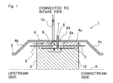
- Fig. 1 is a view showing the schematic construction of an electric heating catalyst (EHC) according to this first embodiment of the present invention.
- the EHC 1 according to this embodiment is arranged in an exhaust pipe or passage of an internal combustion engine mounted on a vehicle.
- the internal combustion engine may be a diesel engine, or may be a gasoline engine.
- the EHC 1 according to this embodiment can also be used in a vehicle which adopts a hybrid system with an electric motor.
- Fig. 1 is a cross sectional view which shows the EHC 1 cut in a longitudinal direction thereof along a central axis A of the exhaust pipe 2 of the internal combustion engine.
- the shape of the EHC 1 is in line symmetry with respect to the central axis A, and hence, in Fig. 1 , only an upper part of the EHC 1 is shown for the sake of convenience.
- the EHC 1 is provided with a catalyst carrier 3, a case 4, a mat 5, an inner pipe 6, electrodes 7, and a ventilation passage 10.
- the catalyst carrier 3 is formed in the shape of a cylinder, and is arranged in such a manner that a central axis thereof is in alignment with the central axis A of the exhaust pipe 2.
- An exhaust gas purification catalyst 15 is carried or supported by the catalyst carrier 3.
- the catalyst carrier 3 is formed of a material which, when energized, becomes an electric resistance to generate heat.
- a material for the catalyst carrier 3 there can be exemplified SiC.
- the catalyst carrier 3 has a plurality of passages which extend in a direction in which an exhaust gas flows (i.e., the direction of the central axis A), and which have a cross section of honeycomb shape vertical to the direction in which the exhaust gas flows. The exhaust gas flows through these passages.
- the cross sectional shape of the catalyst carrier 3 in the direction orthogonal to the central axis A may be elliptical, etc.
- the central axis A is a central axis common to the exhaust pipe 2, the catalyst carrier 3, the inner pipe 6, and the case 4.
- the catalyst carrier 3 is received in the case 4.
- An electrode chamber 9 is formed in the case 4.
- One pair of electrodes 7 (only one electrode being illustrated in Fig. 1 ) are connected to the catalyst carrier 3 through the electrode chamber 9. Electricity is supplied to the electrodes 7 from a battery (not shown). When electricity is supplied to the electrode 7, the catalyst carrier 3 is electrically energized. When the catalyst carrier 3 generates heat by energization thereof, the exhaust gas purification catalyst 15 supported by the catalyst carrier 3 is heated, so that the activation thereof is facilitated.
- the case 4 is formed of metal. As a material which forms the case 4, there can be exemplified a stainless steel material.
- the case 4 has a reception portion 4a which is constructed to include a curved surface parallel to the central axis A, and tapered portions 4b, 4c which serve to connect the reception portion 4a and the exhaust pipe 2 with each other at an upstream side and a downstream side, respectively, of the reception portion 4a.
- the reception portion 4a has a passage cross sectional area which is larger than that of the exhaust pipe 2, and the catalyst carrier 3, the mat 5, and the inner pipe 6 are received in the inside of the reception portion 4a.
- the tapered portions 4b, 4c each take a tapered shape of which the passage cross sectional area decreases in accordance with the increasing distance thereof from the reception portion 4a.
- the mat 5 is inserted between an inner wall surface of the reception portion 4a of the case 4, and an outer peripheral surface of the catalyst carrier 3.
- the catalyst carrier 3 is supported by the mat 5.
- the inner pipe 6 is inserted between the mat 5.
- the mat 5 is divided into a portion at the side of the case 4 and a portion at the side of the catalyst carrier 3 by means of the inner pipe 6.
- the mat 5 is formed of an electric insulation material.
- a material which forms the mat 5 there can be exemplified a ceramic fiber which includes alumina as a main component.
- the mat 5 is wound around the outer peripheral surface of the catalyst carrier 3 and the outer peripheral surface of the inner pipe 6. Due to the insertion of the mat 5 between the catalyst carrier 3 and the case 4, it is possible to suppress electricity from flowing into the case 4 at the time when the catalyst carrier 3 is energized.
- the inner pipe 6 is formed of an electrically insulating material.
- Alumina can be exemplified as a material which forms the inner pipe 6.
- the inner pipe 6 is formed into a tubular shape with the central axis A being located as a center thereof. As shown in Fig. 1 , the inner pipe 6 has a length in the direction of the central axis A longer than that of the mat 5. As a result, the inner pipe 6 has an upstream side end and a downstream side end thereof protruded from an upstream side end face and a downstream side end face of the mat 5, respectively.
- the case 4 and the inner pipe 6 have through holes 4d, 6a opened therein so as to allow the electrodes 7 to pass them, respectively.
- the mat 5 has a space formed therein so as to allow the electrodes 7 to pass them.
- the electrode chamber 9 is formed by such a space which is located between such the inner wall surface of the case 4 and the outer peripheral surface of the catalyst carrier 3, and which has a side wall surface thereof formed by the mat 5.
- Support members 8 which serve to support the electrodes 7, respectively, are arranged in the through holes 4d which are opened in the case 4.
- the support members 8 are formed of an electrically insulating material, and are fitted with no gap between the case 4 and the electrodes 7.
- the EHC 1 is provided with the ventilation passage 10 for ventilating the electrode chamber 9.
- the ventilation passage 10 has one end thereof connected to the electrode chamber 9, and the other end thereof connected to an intake pipe or passage (not shown) of the internal combustion engine.
- the catalyst carrier 3 corresponds to a heat generation element according to the present invention.
- the heat generation element according to the present invention is not limited to a carrier which supports the catalyst, but instead the heat generation element may be a structure which is arranged at an upstream side of the catalyst, for example.
- the case 4 corresponds to a case according to the present invention
- the mat 5 corresponds to an insulating member according to the present invention.
- the ventilation passage 10 corresponds to a ventilation passage according to the present invention.
- arrows indicate flows of exhaust gas, condensed water, and water vapor which has been generated due to the evaporation of condensed water.
- the exhaust gas flowing in the exhaust pipe 2 permeates into the mat 5 and the catalyst carrier 3.
- the moisture in the exhaust gas may condense, thus generating condensed water in the electrode chamber 9.
- the condensed water which has passed through them may come into the electrode chamber 9.
- condensed water If condensed water is present in the electrode chamber 9, it evaporates therein to generate water vapor. In addition, the condensed water, which has accumulated in the mat 5 or the catalyst carrier 3, may evaporate, and may come into the electrode chamber 9 in a state of water vapor. As the humidity in the electrode chamber 9 is raised by such water vapor, there is a fear that the insulation resistance between the electrodes 7 and the case 4 in the electrode chamber 9 may decrease to a large extent.
- the ventilation passage 10 is provided in the EHC 1, so that the electrode chamber 9 is ventilated through this ventilation passage 10.
- the other end of the ventilation passage 10 is connected to the intake pipe of the internal combustion engine.
- gases in the electrode chamber 9 are drawn into the ventilation passage 10 under the action of negative pressure in the intake pipe.
- the electrode chamber 9 can be ventilated.
- the water vapor and the exhaust gas can be removed from the electrode chamber 9 by means of this ventilation.
- the ventilation passage 10 does not necessarily need to be connected to the intake pipe.
- a vacuum pump may be provided on the ventilation passage 10, so that the electrode chamber 9 can be ventilated by the operation of this vacuum pump.
- Fig. 2 is a view showing the schematic construction of an EHC according to a second embodiment.
- a temperature sensor 21 that serves to detect the temperature in an electrode chamber 9.
- a detection value of this temperature sensor 21 is inputted to an electronic control unit (ECU) 20.
- ECU electronice control unit
- a ventilation control valve 11 is arranged in a ventilation passage 10. The ventilation control valve 11 is controlled by the ECU 20. When the ventilation control valve 11 is turned on, the ventilation passage 10 is opened, whereas when the ventilation control valve 11 is turned off, the ventilation passage 10 is blocked or closed.
- the construction other than these is the same as that of the EHC according to the first embodiment.
- the temperature sensor 21 corresponds to a temperature acquisition part an according to the present invention.
- an amount of heat given to the electrode chamber 9 can be calculated based on an operating state of an internal combustion engine, and the temperature in the electrode chamber 9 can also be estimated from the amount of heat thus calculated.
- the ECU 20, which estimates the temperature in the electrode chamber 9, corresponds to the temperature acquisition part according to the present invention.
- Fig. 3 is a flow chart showing a flow of ventilation control according to this second embodiment. This flow is beforehand stored in the ECU 20, and is carried out by the ECU 20 at predetermined intervals.
- step S101 a temperature Te in the electrode chamber 9 detected by the temperature sensor 21 is read in. Then, in step S102, it is determined whether the temperature Te in the electrode chamber 9 is equal to or less than an open air temperature Te0.
- this open air temperature Te0 corresponds to a prescribed temperature according to the present invention.
- the prescribed temperature according to the present invention is not limited to the open air temperature.
- step S102 In cases where it is determined, in step S102, that the temperature Te in the electrode chamber 9 is equal to or less than the open air temperature Te0, then in step S103, the ventilation control valve 11 is turned off. As a result of this, the ventilation passage 10 is blocked. In this case, the ventilation of the electrode chamber 9 is not carried out.
- step S104 the ventilation control valve 11 is turned on. As a result of this, the ventilation passage 10 is opened, so that the ventilation of the electrode chamber 9 is carried out.
- Fig. 4 is a view showing the schematic construction of an EHC according to a third embodiment.
- a ventilation passage is not directly connected to an electrode chamber 9, unlike the first embodiment.
- a ventilation passage 12 is connected to a part of a case 4 in which a mat 5 exists at an upstream side of the electrode chamber 9. The construction other than this is the same as that of the EHC according to the first embodiment.
- arrows indicate flows of exhaust gas, condensed water, and water vapor which has been generated due to the evaporation of condensed water.
- the water vapor and the exhaust gas which have permeated into the mat 5 from an upstream side thereof along the flow of the exhaust gas, are drawn into the ventilation passage 12 before they reach the electrode chamber 9.
- the water vapor and the exhaust gas before coming into the electrode chamber 9 can be removed. Accordingly, it is possible to suppress the water vapor and the exhaust gas from coming into the electrode chamber 9. As a result, the generation of condensed water in the electrode chamber 9 can be suppressed.
- the water vapor and the exhaust gas which have once come into the electrode chamber 9 can be removed through the mat 5.
- Fig. 5 is a view showing the schematic construction of an EHC according to a fourth embodiment.
- a ventilation control valve 13 is arranged in a ventilation passage 12.
- the ventilation control valve 13 is controlled by an ECU 20.
- the ventilation control valve 13 When the ventilation control valve 13 is turned on, the ventilation passage 12 is opened, whereas when the ventilation control valve 13 is turned off, the ventilation passage 12 is blocked or closed.
- the construction other than this is the same as that of the EHC according to the third embodiment.
- Fig. 6 is a flow chart showing a flow of ventilation control according to this fourth embodiment. This flow is beforehand stored in the ECU 20, and is carried out by the ECU 20 at predetermined intervals.
- step S201 it is determined whether an internal combustion engine to which an exhaust pipe 2 is connected has been started. In cases where it is determined, in step S201, that the internal combustion engine has not been started, then in step S202, the ventilation control valve 13 is turned off. As a result of this, the ventilation passage 12 is blocked. In this case, the ventilation of an electrode chamber 9 is not carried out. on the other hand, in cases where it is determined, in step S201, that the internal combustion engine has been started, then in step S203, the ventilation control valve 13 is turned on. As a result of this, the ventilation passage 12 is opened, so that the ventilation of the electrode chamber 9 is carried out.
- Fig. 7 is a view showing the schematic construction of an EHC according to a fifth embodiment.
- a temperature sensor 21 that serves to detect the temperature in an electrode chamber 9.
- a detection value of this temperature sensor 21 is inputted to an ECU 20.
- a ventilation passage 14 branches on the way into a first ventilation passage 14a and a second ventilation passage 14b. Then, the first ventilation passage 14a is connected to the electrode chamber 9, and the second ventilation passage 14b is connected to a part of a case 4 in which a mat 5 exists at an upstream side of the electrode chamber 9.
- a ventilation control valve 15 is arranged at a branch point at which the ventilation passage 14 branches into the first ventilation passage 14a and the second ventilation passage 14b.
- the ventilation control valve 15 is a three-way valve, and is controlled by the ECU 20.
- the ventilation control valve 15 When the ventilation control valve 15 is turned on, the second ventilation passage 14b is opened, whereas when the ventilation control valve 15 is turned off, the first ventilation passage 14a is opened.
- the construction other than these is the same as that of the EHC according to the first embodiment.
- an amount of heat given to the electrode chamber 9 may be calculated based on an operating state of an internal combustion engine, and the temperature in the electrode chamber 9 may also be estimated from the amount of heat thus calculated.
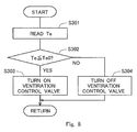
- Fig. 8 is a flow chart showing a flow of ventilation control according to this fifth embodiment. This flow is beforehand stored in the ECU 20, and is carried out by the ECU 20 at predetermined intervals.
- step S301 a temperature Te in the electrode chamber 9 detected by the temperature sensor 21 is read in. Then, in step S302, it is determined whether the temperature Te in the electrode chamber 9 is equal to or less than an open air temperature Te0.
- this open air temperature Te0 corresponds to a prescribed temperature according to the present invention.
- the prescribed temperature according to the present invention is not limited to the open air temperature.
- step S302 In cases where it is determined, in step S302, that the temperature Te in the electrode chamber 9 is equal to or less than the open air temperature Te0, then in step S303, the ventilation control valve 15 is turned on. As a result of this, the second ventilation passage 14b is opened, and the ventilation of the electrode chamber 9 is carried out through the second ventilation passage 14b.
- step S302 in cases where it is determined, in step S302, that the temperature Te in the electrode chamber 9 is higher than the open air temperature Te0, then in step S304, the ventilation control valve 15 is turned off. As a result of this, the first ventilation passage 14a is opened, and the ventilation of the electrode chamber 9 is carried out through the first ventilation passage 14a.
- the ventilation passage 14 may not necessarily be constructed to branch on the way.
- the first and second ventilation passages 14a, 14b may be connected to an intake pipe separately from each other, and a ventilation control valve may be arranged in each of these ventilation passages.
Landscapes
- Chemical & Material Sciences (AREA)
- Engineering & Computer Science (AREA)
- Chemical Kinetics & Catalysis (AREA)
- Health & Medical Sciences (AREA)
- Toxicology (AREA)
- Combustion & Propulsion (AREA)
- Mechanical Engineering (AREA)
- General Engineering & Computer Science (AREA)
- Exhaust Gas After Treatment (AREA)
- Catalysts (AREA)
Claims (7)
- Elektroheizkatalysator (1), der in einem Abgasstrang einer Verbrennungskraftmaschine angeordnet ist, wobei der Katalysator aufweist:ein Wärmeerzeugungselement (3), das bestromt wird, um Wärme zu erzeugen, so dass ein Katalysator durch die Erzeugung von Wärme aufgeheizt wird;ein Gehäuse (4), das das Wärmeerzeugungselement aufnimmt;ein Isolierungselement (5), das zwischen dem Wärmeerzeugungselement und dem Gehäuse angeordnet ist, um das Wärmeerzeugungselement zu tragen und den Strom zu isolieren;Elektroden (7), die durch eine Elektrodenkammer (9), bei der es sich um einen Raum handelt, der sich zwischen einer Innenwandoberfläche des Gehäuses und einer Außenrandoberfläche des Wärmeerzeugungselements befindet, und die eine Seitenwandoberfläche aufweist, die durch das Isolierungselement gebildet wird, mit dem Wärmeerzeugungselement verbunden sind, wobei die Elektroden dem Wärmeerzeugungselement Elektrizität zuführen;eine Belüftungsleitung (10, 12, 14), die so angeordnet ist, dass sie Gase aufnimmt, die von der Elektrodenkammer aufgrund eines Unterdrucks angesaugt werden.
- Elektroheizkatalysator (1) nach Anspruch 1, wobei die Belüftungsleitung (10, 12, 14) mit der Elektrodenkammer (9) verbunden ist.
- Elektroheizkatalysator (1) nach Anspruch 2, ferner aufweisend:einen Temperaturerhaltungsteil (21), der eine Temperatur in der Elektrodenkammer (9) erhält; undeinen Belüftungssteuerungsteil (11), der eine Belüftung der Elektrodenkammer über die Belüftungsleitung (10, 12, 14) durchführt, wenn die Temperatur in der Elektrodenkammer, die durch den Temperaturerhaltungsteil erhalten wird, höher ist als eine vorgegebene Temperatur.
- Elektroheizkatalysator (1) nach Anspruch 1, wobei die Belüftungsleitung (10, 12, 14) mit einem Teil verbunden ist, in dem sich das Isolierungselement (5) an einer Stromaufwärtsseite der Elektrodenkammer (9) befindet.
- Elektroheizkatalysator (1) nach Anspruch 4, ferner aufweisend:einen Belüftungssteuerungsteil (11), der die Belüftung der Elektrodenkammer (9) durch die Belüftungsleitung (10, 12, 14) zu dem Zeitpunkt startet, an dem die Verbrennungskraftmaschine gestartet wird.
- Elektroheizkatalysator (1) nach Anspruch 1, wobei
die Belüftungsleitung (10, 12, 14) aufweist:eine erste Belüftungsleitung (14a), die mit der Elektrodenkammer (9) verbunden ist; undeine zweite Belüftungsleitung (14b), die mit einem Teil verbunden ist, in dem sich das Isolierungselement (5) an einer Stromaufwärtsseite der Elektrodenkammer befindet; undwobei der Elektroheizkatalysator ferner aufweist:einen Temperaturerhaltungsteil (21), der eine Temperatur in der Elektrodenkammer erhält; undeinen Belüftungssteuerungsteil (11), der eine Belüftung der Elektrodenkammer durch die erste Belüftungsleitung durchführt, wenn die Temperatur in der Elektrodenkammer, die durch den Temperaturerhaltungsteil erhalten wird, höher ist als eine vorgegebene Temperatur, und eine Belüftung der Elektrodenkammer durch die zweite Belüftungsleitung durchführt, wenn die Temperatur niedriger als oder gleich der vorgegebenen Temperatur ist. - Elektroheizkatalysator (1) nach einem der Ansprüche 1 bis 6, wobei ein Ende der Belüftungsleitung (10, 12, 14), das an einer gegenüberliegenden Seite eines Endes derselben mit einem Hauptkörper des Elektroheizkatalysators verbunden ist, mit einer Ansaugleitung der Verbrennungskraftmaschine verbunden ist.
Applications Claiming Priority (1)
| Application Number | Priority Date | Filing Date | Title |
|---|---|---|---|
| PCT/JP2010/064283 WO2012025993A1 (ja) | 2010-08-24 | 2010-08-24 | 電気加熱式触媒 |
Publications (4)
| Publication Number | Publication Date |
|---|---|
| EP2610456A1 EP2610456A1 (de) | 2013-07-03 |
| EP2610456A4 EP2610456A4 (de) | 2014-04-02 |
| EP2610456B1 true EP2610456B1 (de) | 2016-08-17 |
| EP2610456B8 EP2610456B8 (de) | 2016-09-28 |
Family
ID=45695291
Family Applications (1)
| Application Number | Title | Priority Date | Filing Date |
|---|---|---|---|
| EP10847168.1A Not-in-force EP2610456B8 (de) | 2010-08-24 | 2010-08-24 | Elektrischer heizkatalysator |
Country Status (5)
| Country | Link |
|---|---|
| US (1) | US8938952B2 (de) |
| EP (1) | EP2610456B8 (de) |
| JP (1) | JP5287990B2 (de) |
| CN (1) | CN103038470B (de) |
| WO (1) | WO2012025993A1 (de) |
Families Citing this family (8)
| Publication number | Priority date | Publication date | Assignee | Title |
|---|---|---|---|---|
| CN103038470B (zh) | 2010-08-24 | 2016-07-06 | 丰田自动车株式会社 | 电加热式催化剂 |
| JP5387777B2 (ja) | 2010-08-31 | 2014-01-15 | トヨタ自動車株式会社 | 電気加熱式触媒 |
| WO2012032652A1 (ja) | 2010-09-10 | 2012-03-15 | トヨタ自動車株式会社 | 電気加熱式触媒 |
| JP5967128B2 (ja) * | 2014-04-11 | 2016-08-10 | トヨタ自動車株式会社 | 通電加熱式触媒装置及びその製造方法 |
| GB2530202A (en) * | 2015-12-10 | 2016-03-16 | Gm Global Tech Operations Inc | Method of operating an aftertreatment system of an internal combustion engine |
| DE102018127074A1 (de) * | 2018-10-30 | 2020-04-30 | Faurecia Emissions Control Technologies, Germany Gmbh | Katalysatorkörper, elektrisch beheizbarer Katalysator, Kraftfahrzeug mit Katalysator und Verfahren zur Herstellung eines Katalysators |
| CN111530395A (zh) * | 2020-05-08 | 2020-08-14 | 中国科学院长春应用化学研究所 | 一种通电制备催化剂的反应装置 |
| JP2022072369A (ja) * | 2020-10-29 | 2022-05-17 | 日本碍子株式会社 | 接合体および接合体の製造方法 |
Family Cites Families (25)
| Publication number | Priority date | Publication date | Assignee | Title |
|---|---|---|---|---|
| US4976929A (en) * | 1988-05-20 | 1990-12-11 | W. R. Grace & Co.-Conn. | Electrically heated catalytic converter |
| JP2818473B2 (ja) | 1990-06-29 | 1998-10-30 | 日本碍子株式会社 | 自動車排ガス浄化用触媒コンバーター装置及び自動車排ガスの浄化方法 |
| US5070694A (en) | 1990-10-31 | 1991-12-10 | W. R. Grace & Co. -Conn. | Structure for electrically heatable catalytic core |
| US5177961A (en) * | 1991-06-26 | 1993-01-12 | W. R. Grace & Co.-Conn. | Upstream collimator for electrically heatable catalytic converter |
| US5238650A (en) * | 1991-09-13 | 1993-08-24 | W. R. Grace & Co.-Conn. | Electrode feed through |
| JPH05231140A (ja) * | 1992-02-18 | 1993-09-07 | Mitsubishi Motors Corp | 排気ガス浄化装置 |
| JPH05269387A (ja) * | 1992-03-26 | 1993-10-19 | Nissan Motor Co Ltd | 排気浄化用触媒コンバータ装置 |
| JPH05317651A (ja) * | 1992-05-18 | 1993-12-03 | Daikin Ind Ltd | 触媒装置 |
| JPH0596421U (ja) * | 1992-05-26 | 1993-12-27 | カルソニック株式会社 | 電熱触媒担体の電極構造 |
| JPH0596424U (ja) | 1992-05-27 | 1993-12-27 | カルソニック株式会社 | 電熱触媒担体の電極取付構造 |
| JPH062534A (ja) * | 1992-06-19 | 1994-01-11 | Mazda Motor Corp | 排気ガス浄化装置 |
| JPH07238825A (ja) * | 1994-02-25 | 1995-09-12 | Toyota Motor Corp | 電気ヒータ付触媒装置 |
| JP3562004B2 (ja) | 1995-02-02 | 2004-09-08 | 日産自動車株式会社 | 内燃機関の触媒浄化装置 |
| JP3494498B2 (ja) * | 1995-04-17 | 2004-02-09 | 日本碍子株式会社 | 電極構造および通電発熱式ヒーター |
| JP2007239556A (ja) | 2006-03-07 | 2007-09-20 | Toyota Motor Corp | 内燃機関の排気浄化システム |
| JP2008014186A (ja) | 2006-07-04 | 2008-01-24 | Toyota Motor Corp | 高電圧供給装置 |
| JP2009142762A (ja) * | 2007-12-14 | 2009-07-02 | Calsonic Kansei Corp | 電気加熱触媒担体及びその製造方法 |
| JP5239678B2 (ja) | 2008-09-19 | 2013-07-17 | マツダ株式会社 | エンジンの排気浄化装置 |
| JP2010242724A (ja) * | 2009-04-10 | 2010-10-28 | Toyota Motor Corp | 車両の制御装置 |
| JP5120500B2 (ja) | 2010-07-15 | 2013-01-16 | トヨタ自動車株式会社 | 内燃機関の排気浄化装置 |
| CN103038470B (zh) | 2010-08-24 | 2016-07-06 | 丰田自动车株式会社 | 电加热式催化剂 |
| JP5387777B2 (ja) * | 2010-08-31 | 2014-01-15 | トヨタ自動車株式会社 | 電気加熱式触媒 |
| WO2012032652A1 (ja) * | 2010-09-10 | 2012-03-15 | トヨタ自動車株式会社 | 電気加熱式触媒 |
| JP2012112302A (ja) * | 2010-11-24 | 2012-06-14 | Toyota Motor Corp | 触媒コンバータ装置 |
| WO2012093481A1 (ja) * | 2011-01-06 | 2012-07-12 | イビデン株式会社 | 排ガス処理装置 |
-
2010
- 2010-08-24 CN CN201080005285.8A patent/CN103038470B/zh not_active Expired - Fee Related
- 2010-08-24 US US13/146,267 patent/US8938952B2/en not_active Expired - Fee Related
- 2010-08-24 EP EP10847168.1A patent/EP2610456B8/de not_active Not-in-force
- 2010-08-24 WO PCT/JP2010/064283 patent/WO2012025993A1/ja not_active Ceased
- 2010-08-24 JP JP2011532368A patent/JP5287990B2/ja not_active Expired - Fee Related
Also Published As
| Publication number | Publication date |
|---|---|
| US20120047881A1 (en) | 2012-03-01 |
| EP2610456A4 (de) | 2014-04-02 |
| JP5287990B2 (ja) | 2013-09-11 |
| EP2610456B8 (de) | 2016-09-28 |
| CN103038470B (zh) | 2016-07-06 |
| EP2610456A1 (de) | 2013-07-03 |
| WO2012025993A1 (ja) | 2012-03-01 |
| CN103038470A (zh) | 2013-04-10 |
| US8938952B2 (en) | 2015-01-27 |
| JPWO2012025993A1 (ja) | 2013-10-28 |
Similar Documents
| Publication | Publication Date | Title |
|---|---|---|
| EP2610456B1 (de) | Elektrischer heizkatalysator | |
| EP2796682B1 (de) | Vorrichtung zur erkennung eines anomalen zustandes für elektrisch beheizbaren katalysator | |
| EP2594759B1 (de) | Abgasreinigungsvorrichtung eines verbrennungsmotors | |
| EP2784280B1 (de) | Steuerungsvorrichtung für einen elektrisch beheizten katalysator und vorrichtung zur schätzung des qualitätsverlustgrades von elektroden für den elektrisch beheizten katalysator | |
| EP2775113B1 (de) | Vorrichtung zur steuerung elektrisch beheizten katalysators | |
| US20130140295A1 (en) | Electric heating catalyst | |
| US9109490B2 (en) | Electric heating catalyst | |
| US20140292350A1 (en) | Failure detection apparatus for an electrically heated catalyst | |
| EP2612700B1 (de) | Elektrisch beheizter katalysator | |
| EP2614878A1 (de) | Elektrisch beheizter katalysator | |
| US9046020B2 (en) | Electrically heated catalyst | |
| EP2614888A1 (de) | Elektrisch beheizter katalysator | |
| JPWO2012014317A1 (ja) | 電気加熱式触媒 |
Legal Events
| Date | Code | Title | Description |
|---|---|---|---|
| PUAI | Public reference made under article 153(3) epc to a published international application that has entered the european phase |
Free format text: ORIGINAL CODE: 0009012 |
|
| 17P | Request for examination filed |
Effective date: 20110919 |
|
| AK | Designated contracting states |
Kind code of ref document: A1 Designated state(s): AL AT BE BG CH CY CZ DE DK EE ES FI FR GB GR HR HU IE IS IT LI LT LU LV MC MK MT NL NO PL PT RO SE SI SK SM TR |
|
| DAX | Request for extension of the european patent (deleted) | ||
| RIN1 | Information on inventor provided before grant (corrected) |
Inventor name: YOSHIOKA, MAMORU Inventor name: KUMAGAI, NORIAKI Inventor name: TAKAGI, NAOYA |
|
| A4 | Supplementary search report drawn up and despatched |
Effective date: 20140304 |
|
| RIC1 | Information provided on ipc code assigned before grant |
Ipc: F01N 3/28 20060101ALI20140226BHEP Ipc: F01N 3/24 20060101ALI20140226BHEP Ipc: F01N 3/20 20060101AFI20140226BHEP Ipc: B01J 37/34 20060101ALI20140226BHEP |
|
| 17Q | First examination report despatched |
Effective date: 20150703 |
|
| GRAP | Despatch of communication of intention to grant a patent |
Free format text: ORIGINAL CODE: EPIDOSNIGR1 |
|
| INTG | Intention to grant announced |
Effective date: 20160310 |
|
| GRAS | Grant fee paid |
Free format text: ORIGINAL CODE: EPIDOSNIGR3 |
|
| GRAA | (expected) grant |
Free format text: ORIGINAL CODE: 0009210 |
|
| GRAT | Correction requested after decision to grant or after decision to maintain patent in amended form |
Free format text: ORIGINAL CODE: EPIDOSNCDEC |
|
| AK | Designated contracting states |
Kind code of ref document: B1 Designated state(s): AL AT BE BG CH CY CZ DE DK EE ES FI FR GB GR HR HU IE IS IT LI LT LU LV MC MK MT NL NO PL PT RO SE SI SK SM TR |
|
| REG | Reference to a national code |
Ref country code: GB Ref legal event code: FG4D |
|
| REG | Reference to a national code |
Ref country code: CH Ref legal event code: EP |
|
| REG | Reference to a national code |
Ref country code: IE Ref legal event code: FG4D |
|
| REG | Reference to a national code |
Ref country code: AT Ref legal event code: REF Ref document number: 821329 Country of ref document: AT Kind code of ref document: T Effective date: 20160915 |
|
| REG | Reference to a national code |
Ref country code: DE Ref legal event code: R096 Ref document number: 602010035717 Country of ref document: DE |
|
| REG | Reference to a national code |
Ref country code: NL Ref legal event code: MP Effective date: 20160817 |
|
| REG | Reference to a national code |
Ref country code: LT Ref legal event code: MG4D |
|
| REG | Reference to a national code |
Ref country code: AT Ref legal event code: MK05 Ref document number: 821329 Country of ref document: AT Kind code of ref document: T Effective date: 20160817 |
|
| PG25 | Lapsed in a contracting state [announced via postgrant information from national office to epo] |
Ref country code: HR Free format text: LAPSE BECAUSE OF FAILURE TO SUBMIT A TRANSLATION OF THE DESCRIPTION OR TO PAY THE FEE WITHIN THE PRESCRIBED TIME-LIMIT Effective date: 20160817 Ref country code: IT Free format text: LAPSE BECAUSE OF FAILURE TO SUBMIT A TRANSLATION OF THE DESCRIPTION OR TO PAY THE FEE WITHIN THE PRESCRIBED TIME-LIMIT Effective date: 20160817 Ref country code: FI Free format text: LAPSE BECAUSE OF FAILURE TO SUBMIT A TRANSLATION OF THE DESCRIPTION OR TO PAY THE FEE WITHIN THE PRESCRIBED TIME-LIMIT Effective date: 20160817 Ref country code: LT Free format text: LAPSE BECAUSE OF FAILURE TO SUBMIT A TRANSLATION OF THE DESCRIPTION OR TO PAY THE FEE WITHIN THE PRESCRIBED TIME-LIMIT Effective date: 20160817 Ref country code: NO Free format text: LAPSE BECAUSE OF FAILURE TO SUBMIT A TRANSLATION OF THE DESCRIPTION OR TO PAY THE FEE WITHIN THE PRESCRIBED TIME-LIMIT Effective date: 20161117 Ref country code: NL Free format text: LAPSE BECAUSE OF FAILURE TO SUBMIT A TRANSLATION OF THE DESCRIPTION OR TO PAY THE FEE WITHIN THE PRESCRIBED TIME-LIMIT Effective date: 20160817 |
|
| PG25 | Lapsed in a contracting state [announced via postgrant information from national office to epo] |
Ref country code: AT Free format text: LAPSE BECAUSE OF FAILURE TO SUBMIT A TRANSLATION OF THE DESCRIPTION OR TO PAY THE FEE WITHIN THE PRESCRIBED TIME-LIMIT Effective date: 20160817 Ref country code: LV Free format text: LAPSE BECAUSE OF FAILURE TO SUBMIT A TRANSLATION OF THE DESCRIPTION OR TO PAY THE FEE WITHIN THE PRESCRIBED TIME-LIMIT Effective date: 20160817 Ref country code: BE Free format text: LAPSE BECAUSE OF NON-PAYMENT OF DUE FEES Effective date: 20160831 Ref country code: GR Free format text: LAPSE BECAUSE OF FAILURE TO SUBMIT A TRANSLATION OF THE DESCRIPTION OR TO PAY THE FEE WITHIN THE PRESCRIBED TIME-LIMIT Effective date: 20161118 Ref country code: PL Free format text: LAPSE BECAUSE OF FAILURE TO SUBMIT A TRANSLATION OF THE DESCRIPTION OR TO PAY THE FEE WITHIN THE PRESCRIBED TIME-LIMIT Effective date: 20160817 Ref country code: ES Free format text: LAPSE BECAUSE OF FAILURE TO SUBMIT A TRANSLATION OF THE DESCRIPTION OR TO PAY THE FEE WITHIN THE PRESCRIBED TIME-LIMIT Effective date: 20160817 Ref country code: SE Free format text: LAPSE BECAUSE OF FAILURE TO SUBMIT A TRANSLATION OF THE DESCRIPTION OR TO PAY THE FEE WITHIN THE PRESCRIBED TIME-LIMIT Effective date: 20160817 Ref country code: PT Free format text: LAPSE BECAUSE OF FAILURE TO SUBMIT A TRANSLATION OF THE DESCRIPTION OR TO PAY THE FEE WITHIN THE PRESCRIBED TIME-LIMIT Effective date: 20161219 |
|
| REG | Reference to a national code |
Ref country code: CH Ref legal event code: PL |
|
| PG25 | Lapsed in a contracting state [announced via postgrant information from national office to epo] |
Ref country code: RO Free format text: LAPSE BECAUSE OF FAILURE TO SUBMIT A TRANSLATION OF THE DESCRIPTION OR TO PAY THE FEE WITHIN THE PRESCRIBED TIME-LIMIT Effective date: 20160817 Ref country code: LI Free format text: LAPSE BECAUSE OF NON-PAYMENT OF DUE FEES Effective date: 20160831 Ref country code: CH Free format text: LAPSE BECAUSE OF NON-PAYMENT OF DUE FEES Effective date: 20160831 Ref country code: EE Free format text: LAPSE BECAUSE OF FAILURE TO SUBMIT A TRANSLATION OF THE DESCRIPTION OR TO PAY THE FEE WITHIN THE PRESCRIBED TIME-LIMIT Effective date: 20160817 |
|
| REG | Reference to a national code |
Ref country code: DE Ref legal event code: R097 Ref document number: 602010035717 Country of ref document: DE |
|
| REG | Reference to a national code |
Ref country code: DE Ref legal event code: R084 Ref document number: 602010035717 Country of ref document: DE |
|
| PG25 | Lapsed in a contracting state [announced via postgrant information from national office to epo] |
Ref country code: SM Free format text: LAPSE BECAUSE OF FAILURE TO SUBMIT A TRANSLATION OF THE DESCRIPTION OR TO PAY THE FEE WITHIN THE PRESCRIBED TIME-LIMIT Effective date: 20160817 Ref country code: CZ Free format text: LAPSE BECAUSE OF FAILURE TO SUBMIT A TRANSLATION OF THE DESCRIPTION OR TO PAY THE FEE WITHIN THE PRESCRIBED TIME-LIMIT Effective date: 20160817 Ref country code: BG Free format text: LAPSE BECAUSE OF FAILURE TO SUBMIT A TRANSLATION OF THE DESCRIPTION OR TO PAY THE FEE WITHIN THE PRESCRIBED TIME-LIMIT Effective date: 20161117 Ref country code: SK Free format text: LAPSE BECAUSE OF FAILURE TO SUBMIT A TRANSLATION OF THE DESCRIPTION OR TO PAY THE FEE WITHIN THE PRESCRIBED TIME-LIMIT Effective date: 20160817 Ref country code: BE Free format text: LAPSE BECAUSE OF FAILURE TO SUBMIT A TRANSLATION OF THE DESCRIPTION OR TO PAY THE FEE WITHIN THE PRESCRIBED TIME-LIMIT Effective date: 20160817 Ref country code: DK Free format text: LAPSE BECAUSE OF FAILURE TO SUBMIT A TRANSLATION OF THE DESCRIPTION OR TO PAY THE FEE WITHIN THE PRESCRIBED TIME-LIMIT Effective date: 20160817 |
|
| REG | Reference to a national code |
Ref country code: IE Ref legal event code: MM4A |
|
| PLBE | No opposition filed within time limit |
Free format text: ORIGINAL CODE: 0009261 |
|
| STAA | Information on the status of an ep patent application or granted ep patent |
Free format text: STATUS: NO OPPOSITION FILED WITHIN TIME LIMIT |
|
| PG25 | Lapsed in a contracting state [announced via postgrant information from national office to epo] |
Ref country code: MC Free format text: LAPSE BECAUSE OF FAILURE TO SUBMIT A TRANSLATION OF THE DESCRIPTION OR TO PAY THE FEE WITHIN THE PRESCRIBED TIME-LIMIT Effective date: 20160817 |
|
| REG | Reference to a national code |
Ref country code: FR Ref legal event code: ST Effective date: 20170602 |
|
| 26N | No opposition filed |
Effective date: 20170518 |
|
| GBPC | Gb: european patent ceased through non-payment of renewal fee |
Effective date: 20161117 |
|
| PG25 | Lapsed in a contracting state [announced via postgrant information from national office to epo] |
Ref country code: FR Free format text: LAPSE BECAUSE OF NON-PAYMENT OF DUE FEES Effective date: 20161017 Ref country code: IE Free format text: LAPSE BECAUSE OF NON-PAYMENT OF DUE FEES Effective date: 20160824 |
|
| PG25 | Lapsed in a contracting state [announced via postgrant information from national office to epo] |
Ref country code: LU Free format text: LAPSE BECAUSE OF NON-PAYMENT OF DUE FEES Effective date: 20160824 Ref country code: SI Free format text: LAPSE BECAUSE OF FAILURE TO SUBMIT A TRANSLATION OF THE DESCRIPTION OR TO PAY THE FEE WITHIN THE PRESCRIBED TIME-LIMIT Effective date: 20160817 |
|
| PGFP | Annual fee paid to national office [announced via postgrant information from national office to epo] |
Ref country code: DE Payment date: 20170815 Year of fee payment: 8 |
|
| PG25 | Lapsed in a contracting state [announced via postgrant information from national office to epo] |
Ref country code: GB Free format text: LAPSE BECAUSE OF NON-PAYMENT OF DUE FEES Effective date: 20161117 |
|
| PG25 | Lapsed in a contracting state [announced via postgrant information from national office to epo] |
Ref country code: CY Free format text: LAPSE BECAUSE OF FAILURE TO SUBMIT A TRANSLATION OF THE DESCRIPTION OR TO PAY THE FEE WITHIN THE PRESCRIBED TIME-LIMIT Effective date: 20160817 Ref country code: HU Free format text: LAPSE BECAUSE OF FAILURE TO SUBMIT A TRANSLATION OF THE DESCRIPTION OR TO PAY THE FEE WITHIN THE PRESCRIBED TIME-LIMIT; INVALID AB INITIO Effective date: 20100824 |
|
| PG25 | Lapsed in a contracting state [announced via postgrant information from national office to epo] |
Ref country code: MK Free format text: LAPSE BECAUSE OF FAILURE TO SUBMIT A TRANSLATION OF THE DESCRIPTION OR TO PAY THE FEE WITHIN THE PRESCRIBED TIME-LIMIT Effective date: 20160817 Ref country code: MT Free format text: LAPSE BECAUSE OF NON-PAYMENT OF DUE FEES Effective date: 20160831 Ref country code: TR Free format text: LAPSE BECAUSE OF FAILURE TO SUBMIT A TRANSLATION OF THE DESCRIPTION OR TO PAY THE FEE WITHIN THE PRESCRIBED TIME-LIMIT Effective date: 20160817 Ref country code: IS Free format text: LAPSE BECAUSE OF FAILURE TO SUBMIT A TRANSLATION OF THE DESCRIPTION OR TO PAY THE FEE WITHIN THE PRESCRIBED TIME-LIMIT Effective date: 20160817 |
|
| PG25 | Lapsed in a contracting state [announced via postgrant information from national office to epo] |
Ref country code: AL Free format text: LAPSE BECAUSE OF FAILURE TO SUBMIT A TRANSLATION OF THE DESCRIPTION OR TO PAY THE FEE WITHIN THE PRESCRIBED TIME-LIMIT Effective date: 20160817 |
|
| REG | Reference to a national code |
Ref country code: DE Ref legal event code: R119 Ref document number: 602010035717 Country of ref document: DE |
|
| PG25 | Lapsed in a contracting state [announced via postgrant information from national office to epo] |
Ref country code: DE Free format text: LAPSE BECAUSE OF NON-PAYMENT OF DUE FEES Effective date: 20190301 |