EP2610528A2 - Unité de pompe électrique - Google Patents
Unité de pompe électrique Download PDFInfo
- Publication number
- EP2610528A2 EP2610528A2 EP12198859.6A EP12198859A EP2610528A2 EP 2610528 A2 EP2610528 A2 EP 2610528A2 EP 12198859 A EP12198859 A EP 12198859A EP 2610528 A2 EP2610528 A2 EP 2610528A2
- Authority
- EP
- European Patent Office
- Prior art keywords
- hydraulic pressure
- motor
- fluid
- pump system
- electric pump
- Prior art date
- Legal status (The legal status is an assumption and is not a legal conclusion. Google has not performed a legal analysis and makes no representation as to the accuracy of the status listed.)
- Granted
Links
Images




Classifications
-
- F—MECHANICAL ENGINEERING; LIGHTING; HEATING; WEAPONS; BLASTING
- F04—POSITIVE - DISPLACEMENT MACHINES FOR LIQUIDS; PUMPS FOR LIQUIDS OR ELASTIC FLUIDS
- F04B—POSITIVE-DISPLACEMENT MACHINES FOR LIQUIDS; PUMPS
- F04B49/00—Control, e.g. of pump delivery, or pump pressure of, or safety measures for, machines, pumps, or pumping installations, not otherwise provided for, or of interest apart from, groups F04B1/00 - F04B47/00
- F04B49/06—Control using electricity
-
- F—MECHANICAL ENGINEERING; LIGHTING; HEATING; WEAPONS; BLASTING
- F16—ENGINEERING ELEMENTS AND UNITS; GENERAL MEASURES FOR PRODUCING AND MAINTAINING EFFECTIVE FUNCTIONING OF MACHINES OR INSTALLATIONS; THERMAL INSULATION IN GENERAL
- F16H—GEARING
- F16H61/00—Control functions within control units of change-speed- or reversing-gearings for conveying rotary motion ; Control of exclusively fluid gearing, friction gearing, gearings with endless flexible members or other particular types of gearing
- F16H61/0021—Generation or control of line pressure
-
- F—MECHANICAL ENGINEERING; LIGHTING; HEATING; WEAPONS; BLASTING
- F16—ENGINEERING ELEMENTS AND UNITS; GENERAL MEASURES FOR PRODUCING AND MAINTAINING EFFECTIVE FUNCTIONING OF MACHINES OR INSTALLATIONS; THERMAL INSULATION IN GENERAL
- F16H—GEARING
- F16H61/00—Control functions within control units of change-speed- or reversing-gearings for conveying rotary motion ; Control of exclusively fluid gearing, friction gearing, gearings with endless flexible members or other particular types of gearing
- F16H61/0021—Generation or control of line pressure
- F16H61/0025—Supply of control fluid; Pumps therefor
- F16H61/0031—Supply of control fluid; Pumps therefor using auxiliary pumps, e.g. pump driven by a different power source than the engine
-
- F—MECHANICAL ENGINEERING; LIGHTING; HEATING; WEAPONS; BLASTING
- F16—ENGINEERING ELEMENTS AND UNITS; GENERAL MEASURES FOR PRODUCING AND MAINTAINING EFFECTIVE FUNCTIONING OF MACHINES OR INSTALLATIONS; THERMAL INSULATION IN GENERAL
- F16H—GEARING
- F16H59/00—Control inputs to control units of change-speed- or reversing-gearings for conveying rotary motion
- F16H59/68—Inputs being a function of gearing status
- F16H59/72—Inputs being a function of gearing status dependent on oil characteristics, e.g. temperature, viscosity
Definitions
- the invention relates generally to an electric pump system, and more specifically to an electric pump system that is suitable for use in a vehicle that has an idling stop function.
- a vehicle that has a so-called idling stop function of automatically stopping an engine when the vehicle temporarily stops for parking or temporarily stops at a red light, and automatically starting the engine in response to a driver's vehicle starting operation.
- an idling time is reduced and therefore the fuel efficiency is improved.
- a mechanical pump that is driven by the engine is usually mounted in the vehicle, and hydraulic fluid is supplied from the mechanical pump through an oil passage to hydraulically-actuated devices such as a transmission mechanism. Therefore, when the engine is automatically stopped by the above-described idling stop function, the mechanical pump is also stopped. In this case, when a driver attempts to start the vehicle after a restart of the engine, the hydraulic pressure that is required to actuate the hydraulically-actuated device may not be ensured and a shock may occur in the vehicle.
- a hydraulic pressure sensor that detects the hydraulic pressure in an oil passage and an electric pump system that uses a motor as a drive source are provided. While an engine is automatically stopped by an idling stop function, if the hydraulic pressure that is detected by the hydraulic pressure sensor becomes lower than or equal to a predetermined value, the hydraulic pressure that is required to actuate a hydraulically-actuated device is ensured by supplying hydraulic fluid from the electric pump system to the hydraulically-actuated device. In this way, it is possible to reliably ensure the hydraulic pressure that is required to actuate the hydraulically-actuated device at the restart of the engine. As a result, it is possible to suppress the above-described shock.
- the hydraulic pressure of the hydraulic fluid that is supplied from the mechanical pump to the hydraulically-actuated device is generally higher by several tens of times than the hydraulic pressure of the hydraulic fluid that is supplied from the electric pump system to the hydraulically-actuated device. Therefore, if the resolution of the hydraulic pressure sensor is set to a resolution corresponding to the hydraulic pressure of the mechanical pump, it is difficult to highly accurately detect the hydraulic pressure of the hydraulic fluid with the use of the hydraulic pressure sensor for the mechanical pump. Therefore, when drive control on the electric pump system is executed on the basis of the hydraulic pressure that is detected by the hydraulic pressure sensor for the mechanical pump, the hydraulic pressure of the hydraulic fluid may increase more than necessary and electricity may be wastefully consumed by the electric pump system.
- An aspect of the invention relates to an electric pump system, including: an oil pump that supplies hydraulic fluid to a hydraulically-actuated device through an oil passage as a motor is driven; and a control unit that executes drive control on the motor based on a hydraulic pressure of the hydraulic fluid in the oil passage.
- the control unit estimates a hydraulic pressure value of the hydraulic fluid based on a driving current for the motor and a rotation speed of the motor.
- FIG. 1 an electric pump system according to a first embodiment of the invention will be described with reference to FIG. 1 to FIG. 5 and FIGs. 6A and 6B .
- the electric pump system according to the first embodiment is used in a system that supplies hydraulic fluid to a transmission mechanism of a vehicle.
- a vehicle that has the above-described idling stop function is employed as the vehicle in the first embodiment.
- an oil supply system according to the first embodiment will be described with reference to FIG. 1 .
- hydraulic fluid stored in an oil pan 1 of the vehicle is drawn up through a mechanical pump 2.
- the mechanical pump 2 operates using an engine 3 as a drive source.
- the mechanical pump 2 pressurizes the hydraulic fluid drawn up from the oil pan 1, and delivers the pressurized hydraulic fluid to a transmission mechanism 4 through a main oil passage La. That is, in the oil supply system, when the engine 3 is driven, the hydraulic fluid is supplied to the transmission mechanism 4 on the basis of an operation of the mechanical pump 2.
- An auxiliary oil passage Lb is connected to a midpoint of the main oil passage La, and an electric pump system 10 according to the present embodiment is provided on the auxiliary oil passage Lb.
- the electric pump system 10 is formed of an oil pump 11, a motor 12, and an electric oil pump (EOP) ECU 13.
- the oil pump 11 is provided at a midpoint of the auxiliary oil passage Lb.
- the motor 12 drives the oil pump 11.
- the EOPECU 13 executes drive control on the motor 12.
- the oil pump 11 is operated by driving the motor 12.
- the oil pump 11 draws up the hydraulic fluid from the oil pan 1 and pressurizes the hydraulic fluid, and then delivers the pressurized hydraulic fluid to the transmission mechanism 4 through the auxiliary oil passage Lb.
- a check valve 5 is provided at a midpoint of the auxiliary oil passage Lb.
- the check valve 5 prevents backflow of the hydraulic fluid from the main oil passage La.
- the electric pump system 10 operates instead of the mechanical pump 2, thus making it possible to supply the hydraulic fluid to the transmission mechanism 4.
- the oil supply system includes a hydraulic pressure sensor 7 and a temperature sensor 8 that detects a temperature Toil of the hydraulic fluid.
- the hydraulic pressure sensor 7 detects a hydraulic pressure Poil of the hydraulic fluid in the main oil passage La.
- the temperature sensor 8 detects the temperature Toil of the hydraulic fluid in the main oil passage La.
- Outputs from the sensors are input into a host ECU 6 that comprehensively executes the idling stop function of the vehicle.
- the host ECU 6 detects the fact that the vehicle is temporarily stopped on the basis of state quantities of the vehicle, such as a vehicle speed and an accelerator operation amount, which are detected by various sensors mounted in the vehicle, the host ECU 6 temporarily stops the engine 3.
- the host ECU 6 monitors the hydraulic pressure of the hydraulic fluid with the use of the hydraulic pressure sensor 7, and determines whether the hydraulic pressure of the hydraulic fluid is higher than or equal to a target hydraulic pressure.
- the target hydraulic pressure is set to a hydraulic pressure that is required to be supplied to the transmission mechanism 4 in order to suppress the above-described shock.
- the host ECU 6 computes a value of current that should be supplied to the motor 12 of the electric pump system 10 on the basis of the difference between the hydraulic pressure of the hydraulic fluid and the target hydraulic pressure, and outputs a drive request signal that contains the computed current command value to the EOPECU (control unit) 13 via an in-vehicle network.
- the host ECU 6 detects the temperature Toil of the hydraulic fluid with the use of the temperature sensor 8 at predetermined intervals, and outputs the information on the detected fluid temperature to the EOPECU 13 via the in-vehicle network.
- the host ECU 6 detects the fact that a vehicle start operation is performed by a driver on the basis of the state quantities of the vehicle, which are detected by the various sensors, during a period in which the engine 3 is temporarily stopped, the host ECU 6 restarts the engine 3.
- the host ECU 6 restarts the engine 3
- the host ECU 6 outputs a stop request signal to the EOPECU 13 via the in-vehicle network.
- the EOPECU 13 executes drive control on the motor 12 on the basis of the drive request signal, the fluid temperature information and the stop request signal from the host ECU 6. Next, the electrical configuration and the operation of the EOPECU 13 will be described in detail with reference to FIG. 2 .
- the EOPECU 13 includes an inverter circuit 14 and a microcomputer 16.
- the inverter circuit 14 converts direct-current power into three-phase alternating-current power.
- the microcomputer 16 executes drive control on the motor 12 by driving the inverter circuit 14 through pulse width modulation (PWM).
- PWM pulse width modulation
- the EOPECU 13 includes a memory 17 and a timer 18.
- the inverter circuit 14 is formed of a parallel circuit that includes a pair of transistors T1, T2, a pair of transistors T3, T4 and a pair of transistors T5, T6.
- Three-phase alternating-current power is generated from electric power output from connection points at which respective pairs of transistors are connected to each other.
- the microcomputer 16 performs switching operations of the transistors T1 to T6 of the inverter circuit 14 by outputting gate drive signals to the transistors T1 to T6.
- a power supply 20 such as an in-vehicle battery
- the obtained three-phase alternating-current power is supplied to the motor 12 through a UL line, a VL line, and a WL line.
- a current sensor 19 is provided at a midpoint of a ground line that extends from the transistors T2, T4, T6.
- the current sensor 19 detects the sum of values of U-phase, V-phase and W-phase currents that are supplied to the motor 12, that is, a driving current (actual current) that is supplied to the motor 12.
- An output from the current sensor 19 is input into the microcomputer 16.
- the microcomputer 16 executes feedback control on the driving current for the motor 12 on the basis of the current command value that is contained in the drive request signal. Specifically, the microcomputer 16 executes feedback control in which the gate drive signals for the inverter circuit 14 at each time are generated and output to the inverter circuit 14 in order to bring the driving current for the motor 12, which is detected by the current sensor 19, closer to the current command value that is contained in the drive request signal.
- the motor 12 is driven in accordance with the current command value from the host ECU 6, and the hydraulic pressure of the hydraulic fluid approaches the target hydraulic pressure.
- the hydraulic pressure sensor 7 shown in FIG. 1 detects the hydraulic pressure of the hydraulic fluid that is supplied from the mechanical pump 2 to the transmission mechanism 4. Therefore, the resolution of the hydraulic pressure sensor 7 is set to a resolution that corresponds to the mechanical pump 2. On the other hand, the hydraulic pressure of the hydraulic fluid that is supplied from the mechanical pump 2 to the transmission mechanism 4 is higher by several tens of times than the hydraulic pressure of the hydraulic fluid that is supplied from the electric pump system 10 to the transmission mechanism 4. Thus, in the hydraulic pressure sensor 7, it is difficult to accurately detect the magnitude of the hydraulic pressure of the hydraulic fluid that is supplied from the electric pump system 10 to the transmission mechanism 4.
- the hydraulic pressure of the hydraulic fluid that is supplied from the electric pump system 10 to the transmission mechanism 4 may increase more than necessary and electricity may be wastefully consumed by the electric pump system 10.
- the magnitude of the hydraulic pressure of the hydraulic fluid that is supplied from the electric pump system 10 to the transmission mechanism 4 is determined on the basis of the power output from the motor 12.
- the power output from the motor 12 is correlated with the driving current for the motor 12 and the rotation speed of the motor 12. Furthermore, as the fluid temperature of the hydraulic fluid increases, the viscosity of hydraulic fluid decreases and the hydraulic pressure of the hydraulic fluid decreases. That is, there is also a correlation between the fluid temperature and the hydraulic pressure of the hydraulic fluid.
- the hydraulic pressure of the hydraulic fluid that is supplied from the electric pump system 10 to the transmission mechanism 4 is estimated on the basis of the driving current for the motor 12 and the rotation speed of the motor 12, and the current command value is set on the basis of the estimated hydraulic pressure.
- the set current command value is corrected on the basis of the fluid temperature of the hydraulic fluid.
- the EOPECU 13 executes drive control on the motor 12 on the basis of the corrected current command value.
- Control shown in FIG. 3 is started when the drive request signal is transmitted to the EOPECU 13 from the host ECU 6. After that, the control is repeatedly executed at predetermined computation intervals during a period until the stop request signal is transmitted to the EOPECU 13 from the host ECU 6.
- step S1 the process of estimating the hydraulic pressure of the hydraulic fluid that is supplied from the electric pump system 10 to the transmission mechanism 4 is executed (step S1).
- step S10 a driving current Iw for the motor 12 and a rotation speed (number of revolutions) N of the motor 12 are detected (step S10).
- the driving current Iw for the motor 12 is detected by the current sensor 19.
- the rotation speed N of the motor 12 is determined on the basis of the duty ratio of each of the gate drive signals (the ratio of a period of time during which each gate drive signal is on with respect to a unit period of time) that are input into the inverter circuit 14.
- the rotation speed N of the motor 12 is obtained on the basis of the duty ratio of each gate drive signal.
- a hydraulic pressure Pe of the hydraulic fluid is estimated on the basis of the driving current Iw for the motor 12 and the rotation speed N of the motor 12.
- the correlation among the driving current Iw for the motor 12, the rotation speed N of the motor 12 and the estimated hydraulic pressure Pe is empirically obtained in advance, and the correlation among them is mapped as illustrated in FIG. 5 and is stored in the memory 17 of the EOPECU 13. In the map shown in FIG.
- the correlations between the driving current Iw for the motor 12 and the estimated hydraulic pressure Pe are indicated by the respective solid lines m1 to m8 (where N1 ⁇ N2 ⁇ ... ⁇ N7 ⁇ N8).
- the estimated hydraulic pressure Pe becomes higher as the rotation speed N of the motor 12 becomes lower in the case where the driving current Iw for the motor 12 is the same, and the estimated hydraulic pressure Pe becomes higher as the driving current Iw for the motor 12 becomes higher in the case where the rotation speed N of the motor 12 is the same.
- the estimated hydraulic pressure Pe is computed on the basis of the driving current Iw for the motor 12 and the rotation speed N of the motor 12 using the map shown in FIG. 5 . Values that are not on the solid lines m1 to m8 in the map shown in FIG. 5 are computed, as needed, through estimation using values on the solid lines.
- the fluid temperature Toil of the hydraulic fluid is detected on the basis of the information on the fluid temperature provided from the host ECU 6, and a fluid temperature correction gain Kt is set on the basis of the detected fluid temperature Toil of the hydraulic fluid.
- the fluid temperature correction gain Kt is set to one of first to third gains Kt1 to Kt3.
- first to third gains Kt1 to Kt3 there is a correlation that Kt1 > Kt2 > Kt3.
- the fluid temperature Toil of the hydraulic fluid falls within a low fluid temperature range, that is, 0°C ⁇ Toil ⁇ 40°C.
- the fluid temperature correction gain Kt is set to the first gain Kt1.
- the fluid temperature Toil of the hydraulic fluid falls within an intermediate fluid temperature range, that is, 40°C ⁇ Toil ⁇ 80°C. In this case, the fluid temperature correction gain Kt is set to the second gain Kt2.
- the fluid temperature correction gain Kt is set to the third gain Kt3.
- the estimated hydraulic pressure Pe is corrected by multiplying the estimated hydraulic pressure Pe, which is computed in step S11, by the fluid temperature correction gain Kt.
- step S2 it is determined whether the estimated hydraulic pressure Pe is the target hydraulic pressure (step S2).
- the target hydraulic pressure is set to a value that falls within a range of which the lower limit is a first threshold Pth11 and of which the upper limit is a second threshold Pth12.
- step S2 it is determined whether the estimated hydraulic pressure Pe satisfies the relationship, Pth11 ⁇ Pe ⁇ Pth12.
- the current command value Ia is corrected to be increased or reduced as described in the following b1) and b2) (step S3).
- the estimated hydraulic pressure Pe is lower than or equal to the first threshold Pth11. That is, the hydraulic pressure of the hydraulic fluid is lower than the target hydraulic pressure, and the power output from the motor 12 is insufficient. In this case, the current command value Ia is corrected to be increased by a correction value ⁇ Ia. As a result, the power that is output from the motor 12 increases.
- the estimated hydraulic pressure Pe is higher than or equal to the second threshold Pth12. That is, the hydraulic pressure of the hydraulic fluid is higher than the target hydraulic pressure, and the power output from the motor 12 is excessive.
- the current command value Ia is corrected to be reduced by a correction value ⁇ Ia. As a result, the power that is output from the motor 12 decreases.
- the current command value contained in the drive request signal is used as the current command value Ia. After that, the immediately preceding current command value Ia is used.
- step S4 drive control on the motor 12 is executed on the basis of the corrected current command value Ia.
- the estimated hydraulic pressure Pe is the target hydraulic pressure (YES in step S2)
- drive control on the motor 12 is executed on the basis of the immediately preceding current command value Ia (step S4).
- the hydraulic pressure of the hydraulic fluid is estimated on the basis of the driving current for the motor 12, the rotation speed of the motor 12 and the fluid temperature of the hydraulic fluid. Therefore, it is possible to highly accurately detect the hydraulic pressure of the hydraulic fluid. As a result, as shown in FIG. 6B , it is possible to detect, for example, that the hydraulic pressure of the hydraulic fluid is higher than or equal to the second threshold Pth12 at time t10 even without using the hydraulic pressure sensor 7. At this time, in the electric pump system 10, as indicated by the solid line in FIG. 6A , after time t10, the current command value Ia is corrected to be reduced gradually by an amount corresponding to the correction value ⁇ Ia.
- the power output from the motor 12 gradually decreases.
- the hydraulic pressure of the hydraulic fluid is gradually reduced.
- the current command value Ia is no longer corrected as shown in FIG. 6A . Therefore, the hydraulic pressure of the hydraulic fluid converges to the target hydraulic pressure.
- a hydraulic pressure that is required to actuate the transmission mechanism 4 is reliably ensured, it is possible to reduce the current command value Ia for the motor 12 from the value I1 to the value I2 as shown in FIG. 6A .
- the hydraulic pressure of the hydraulic fluid is estimated on the basis of the driving current for the motor 12 and the rotation speed of the motor 12.
- Drive control on the motor 12 is executed on the basis of the estimated hydraulic pressure Pe.
- the fluid temperature correction gain Kt is set on the basis of the fluid temperature of the hydraulic fluid.
- the estimated hydraulic pressure Pe is corrected on the basis of the set fluid temperature correction gain Kt. Therefore, it is possible to further highly accurately estimate the hydraulic pressure of the hydraulic fluid.
- the fluid temperature correction gain Kt is set to one of the first to third gains Kt1 to Kt3 for the respective three fluid temperature ranges defined in advance. Therefore, the EOPECU 13 is required just to execute computation process of correcting the estimated hydraulic pressure Pe for each of the three fluid temperature ranges. Therefore, it is possible to reduce the computation load on the EOPECU 13.
- the current command value Ia for the motor 12 is corrected to be increased or reduced by the correction value ⁇ Ia such that the estimated hydraulic pressure Pe approaches the target hydraulic pressure.
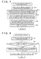
- FIG. 7 shows an electric pump system according to a modified example to the first embodiment.
- An in-vehicle battery is usually used as a power source for the motor 12. Therefore, when the voltage value of the in-vehicle battery decreases due to aged degradation, or the like, of the in-vehicle battery, the power output from the motor 12 also decreases. Accordingly, the hydraulic pressure of the hydraulic fluid decreases. That is, there is also a correlation between the hydraulic pressure of the hydraulic fluid and the power supply voltage of the motor 12. As shown in FIG. 7 that shows a flowchart corresponding to the estimated hydraulic pressure computing process illustrated in FIG.
- the estimated hydraulic pressure Pe is corrected by multiplying the estimated hydraulic pressure Pe by the fluid temperature correction gain Kt and the voltage correction gain Kv.
- the electric pump system according to the second embodiment is used in a system that supplies hydraulic fluid to a transmission mechanism of a vehicle.
- the basic configuration of an oil supply system to which the electric pump system according to the second embodiment is applied is similar to that of the oil supply system illustrated in FIG. 1 .
- a multiplication coefficient (correction gain) Ki is set for the correction value ⁇ Ia that is used to correct the current command value Ia for the motor 12.
- the correction gain Ki is set to a first gain Ki1 as its initial value.
- the correction gain Ki is set to a second gain Ki2 that is smaller than the first gain Ki1. That is, in the present embodiment, two correction values, that is, a first correction value obtained by multiplying the correction value ⁇ Ia by the first gain Ki1 and a second correction value obtained by multiplying the correction value ⁇ Ia by the second gain Ki2 are used as the current command value Ia.
- step S5 when the estimated hydraulic pressure Pe is not the target hydraulic pressure (NO in step S2), the current command value Ia is corrected to be increased or reduced as described in the following c1) and c2) (step S5).
- the estimated hydraulic pressure Pe is lower than or equal to the first threshold Pth11. In this case, the estimated hydraulic pressure Pe is corrected to be increased by a value obtained by multiplying the correction value ⁇ Ia by the correction gain Ki. c2) The estimated hydraulic pressure Pe is higher than or equal to the second threshold Pth12. In this case, the estimated hydraulic pressure Pe is corrected to be reduced by a value obtained by multiplying the correction value ⁇ Ia by the correction gain Ki.
- the correction gain Ki is set to the first gain Ki1 as its initial value when the drive request signal is transmitted from the host ECU 6 to the EOPECU 13.
- the process shown in FIG. 9 is started when a drive request signal is transmitted from the host ECU 6. After that, the control is repeatedly executed at predetermined computation intervals during a period until the stop request signal is transmitted to the EOPECU 13 from the host ECU 6.
- the estimated hydraulic pressure Pe is computed through the estimated hydraulic pressure computing process illustrated in FIG. 4 or FIG. 7 (step S20).
- the estimated hydraulic pressure Pe is monitored to determine whether the estimated hydraulic pressure Pe is a value around the target hydraulic pressure.
- a third threshold Pth21 and a fourth threshold Pth22 are set for the estimated hydraulic pressure Pe.
- the third threshold Pth21 is a value that is slightly larger than the first threshold Pth11.
- the fourth threshold Pth22 is a value that is slightly smaller than the second threshold Pth12.
- the estimated hydraulic pressure Pe satisfies the relationship, Pth21 ⁇ Pe ⁇ Pth22, it is determined that the estimated hydraulic pressure Pe is a value around the target hydraulic pressure.
- the estimated hydraulic pressure Pe is a value around the target hydraulic pressure (YES in step S21)
- the timer 18 incorporated in the EOPECU 13 starts counting up (step S22).
- the estimated hydraulic pressure Pe is computed at predetermined intervals through the estimated hydraulic pressure computing process illustrated in FIG. 4 or FIG.
- step S23 it is determined that the estimated hydraulic pressure Pe is around the target hydraulic pressure and in a stable state, and the correction gain Ki is changed to the second gain Ki2 (step S24).
- the response of the power output from the motor 12 decreases.
- step S25 the value of the timer 18 is reset.
- step S23 when the estimated hydraulic pressure Pe becomes a value that is not around the target hydraulic pressure before the value of the timer 18 reaches the predetermined value Ta (NO in step S23), the value of the timer 18 is reset without changing the correction gain Ki to the second gain Ki2 (step S25).
- the correction value ⁇ Ia for the current command value Ia is multiplied by the first gain Ki1 at time t20. Therefore, as shown in FIG. 10A , an amount of change in the current command value Ia is large. That is, the power output from the motor 12 significantly decreases. Therefore, as shown in FIG. 10B , it is possible to bring the hydraulic pressure of the hydraulic fluid to a value around the target hydraulic pressure in a short period of time.
- the correction gain Ki is set for the correction value ⁇ Ia that is used to correct the current command value Ia for the motor 12 to increase or reduce the current command value Ia.
- the electric pump system according to the third embodiment is used in a system that supplies hydraulic fluid to a transmission mechanism of a vehicle.
- the basic configuration of the electric pump system according to the third embodiment is similar to that of the electric pump system according to the second embodiment.
- the correction gain Ki set for the correction value ⁇ Ia of the current command value Ia is returned from the second gain Ki2 to the first gain Ki1.
- the details of the control for returning the correction gain Ki to the first gain Ki1 will be described with reference to FIG. 11 and FIG. 12 .
- the procedure in which the EOPECU 13 returns the gain Ki of the correction value ⁇ Ia from the second gain Ki2 to the first gain Ki1 will be described with reference to FIG. 11 .
- the process shown in FIG. 11 is repeatedly executed at predetermined computation intervals when the correction gain Ki is set at the second gain Ki2.
- step S30 it is determined whether fluid temperature range boundary crossing occurs on the basis of the fluid temperature Toil of the hydraulic fluid. Specifically, when the fluid temperature range to which the immediately preceding detected fluid temperature belongs differs from the fluid temperature range to which the presently detected fluid temperature belongs on the basis of the fluid temperature information from the host ECU 6, it is determined that fluid temperature range boundary crossing occurs. For example, when the immediately preceding detected fluid temperature Toil is a temperature that falls within the low fluid temperature range and the presently detected fluid temperature Toil is a temperature that falls within the intermediate fluid temperature range, it is determined that fluid temperature range boundary crossing occurs. When fluid temperature range boundary crossing occurs (YES in step S30), the correction gain Ki is changed to the first gain Ki1 (step S31).
- step S30 when no fluid temperature range boundary crossing occurs (NO in step S30), the series of processes is ended.
- an example of an operation (operation) of the electric pump system 10 according to the present embodiment will be described with reference to FIG. 12 .
- the hydraulic pressure of the hydraulic fluid when the hydraulic pressure of the hydraulic fluid is stably at the target hydraulic pressure and the fluid temperature of the hydraulic fluid is a temperature that falls within the low fluid temperature range, if the fluid temperature of the hydraulic fluid increases from time t31 and the temperature shifts from the low fluid temperature range to the intermediate fluid temperature range, the viscosity of the hydraulic fluid decreases. Therefore, the hydraulic pressure of the hydraulic fluid may decrease to a hydraulic pressure P1 that is lower than the target hydraulic pressure. At this time, if the correction gain Ki remains at the second gain Ki2, the response of the power output from the motor 12 is slow. Therefore, as indicated by a long dashed two short dashed line in FIG. 12 , a long period of time may be required to cause the hydraulic pressure of the hydraulic fluid to converge to the target hydraulic pressure.
- the correction gain Ki is changed from the second gain Ki2 to the first gain Ki1 at time t32. Therefore, the response of the power output from the motor 12 increases.
- the solid line in FIG. 12 it is possible to reduce a period of time that is required to cause the hydraulic pressure of the hydraulic fluid to converge to the target hydraulic pressure. Therefore, it is possible to further reliably suppress noise, or the like, that is generated from the electric pump system 10 as the motor 12 is driven.
- the above-described embodiments may be modified into the following alternative embodiments as needed.
- the correction gain Ki is changed from the second gain Ki2 to the first gain Ki1.
- the changed gain may be a value larger than the second gain Ki2 instead of the first gain Ki1.
- the current command value Ia for the motor 12 is corrected by adding the correction value ⁇ Ia to the current command value Ia or subtracting the correction value ⁇ Ia from the current command value Ia.
- a multiplication coefficient (gain) may be set for the current command value Ia and the current command value Ia may be corrected by increasing or reducing the gain. That is, the method of correcting the current command value Ia is not particularly limited as long as the current command value Ia for the motor 12 is increased or reduced such that the estimated hydraulic pressure Pe approaches the target hydraulic pressure.
- the fluid temperature correction gain Kt is set for the estimated hydraulic pressure Pe, and the fluid temperature correction gain Kt is set to one of the values set for the respective three fluid temperature ranges.
- the estimated hydraulic pressure Pe is corrected on the basis of the fluid temperature of the hydraulic fluid.
- a map that shows the correlation among the driving current Iw for the motor 12, the rotation speed N of the motor 12 and the estimated hydraulic pressure Pe as illustrated in FIG. 5 is prepared in advance for each of the three fluid temperature ranges. Then, the map that is used to compute the estimated hydraulic pressure Pe may be selected on the basis of the fluid temperature of the hydraulic fluid at that time. With such a method as well, it is possible to easily correct the estimated hydraulic pressure Pe for each of the three fluid temperature ranges.
- the three fluid temperature ranges are set for the fluid temperature of the hydraulic fluid.
- the number of set fluid temperature ranges may be changed as needed.
- the estimated hydraulic pressure Pe is corrected for each of the three fluid temperature ranges.
- such correction process may be omitted. That is, in the process illustrated in FIG. 4 , it is possible to omit the processes of steps S12 and S13.
- the EOPECU 13 detects the fluid temperature of the hydraulic fluid on the basis of the fluid temperature information provided from the host ECU 6.
- the EOPECU 13 may directly detect the fluid temperature of the hydraulic fluid by directly receiving the output from the temperature sensor 8.
- the invention is applied to the electric pump system that is used in the oil supply system that includes the mechanical pump 2.
- the system to which the invention is applied is not limited to this.
- the invention may be applied to an electric pump system that is used in an oil supply system that includes a pump other than a mechanical pump.
- the electric pump system to which the invention is applied is not limited to the electric pump system that is used in the oil supply system that supplies hydraulic fluid to the transmission mechanism of the vehicle.
- the invention may be applied to an electric pump system that is used in an oil supply system that supplies hydraulic fluid to an appropriate hydraulically-actuated device.
- hydraulic fluid that is stored in an oil pan is supplied to a transmission mechanism through an oil passage by driving an oil pump with the use of a motor.
- An EOPECU estimates a hydraulic pressure of the hydraulic fluid on the basis of a driving current for the motor and a rotation speed of the motor, and executes drive control on the motor on the basis of the estimated hydraulic pressure value.
Landscapes
- Engineering & Computer Science (AREA)
- General Engineering & Computer Science (AREA)
- Mechanical Engineering (AREA)
- Control Of Transmission Device (AREA)
- Control Of Positive-Displacement Pumps (AREA)
- Fluid-Pressure Circuits (AREA)
Applications Claiming Priority (1)
| Application Number | Priority Date | Filing Date | Title |
|---|---|---|---|
| JP2011288504A JP5891787B2 (ja) | 2011-12-28 | 2011-12-28 | オイル供給システム |
Publications (3)
| Publication Number | Publication Date |
|---|---|
| EP2610528A2 true EP2610528A2 (fr) | 2013-07-03 |
| EP2610528A3 EP2610528A3 (fr) | 2018-01-24 |
| EP2610528B1 EP2610528B1 (fr) | 2020-08-05 |
Family
ID=47678504
Family Applications (1)
| Application Number | Title | Priority Date | Filing Date |
|---|---|---|---|
| EP12198859.6A Active EP2610528B1 (fr) | 2011-12-28 | 2012-12-21 | Unité de pompe électrique |
Country Status (4)
| Country | Link |
|---|---|
| US (1) | US9309881B2 (fr) |
| EP (1) | EP2610528B1 (fr) |
| JP (1) | JP5891787B2 (fr) |
| CN (1) | CN103185002B (fr) |
Cited By (3)
| Publication number | Priority date | Publication date | Assignee | Title |
|---|---|---|---|---|
| WO2016193187A1 (fr) * | 2015-06-03 | 2016-12-08 | Continental Automotive Gmbh | Procédé pour déterminer la pression régnant dans un système de refoulement de fluide |
| EP3289212A1 (fr) * | 2015-04-27 | 2018-03-07 | Continental Automotive GmbH | Procédé pour augmenter la précision d'une détection de pression sans capteur |
| EP3789612A1 (fr) | 2019-09-06 | 2021-03-10 | Weber-Hydraulik GmbH | Appareil hydraulique portable fonctionnant sur accumulateur pour outils de sauvetage hydraulique |
Families Citing this family (16)
| Publication number | Priority date | Publication date | Assignee | Title |
|---|---|---|---|---|
| JP5938901B2 (ja) | 2011-12-28 | 2016-06-22 | 株式会社ジェイテクト | モータ制御装置および電動ポンプユニット |
| CN103629344B (zh) * | 2013-11-18 | 2018-07-06 | 浙江吉利控股集团有限公司 | 湿式双离合自动变速器传动系统及其传动控制方法 |
| DE102014222404A1 (de) * | 2014-11-03 | 2016-05-04 | Continental Automotive Gmbh | Verfahren zur Überprüfung eines mit einem Druck korrelierenden Parameters in einem druckabhängigen Fluidfördersystem, Steuergerät und Fluidfördersystem |
| KR101673699B1 (ko) * | 2014-11-19 | 2016-11-07 | 현대자동차주식회사 | 토크 어시스트 amt의 eop 변속 패턴 개선 방법 |
| JP6428287B2 (ja) * | 2015-01-19 | 2018-11-28 | 株式会社ジェイテクト | データ送受信装置 |
| JP6429697B2 (ja) * | 2015-03-26 | 2018-11-28 | ジヤトコ株式会社 | 車両用油圧制御装置 |
| DE102015210166A1 (de) * | 2015-06-02 | 2016-12-08 | Zf Friedrichshafen Ag | Verfahren zur Bestimmung des Ausgangsdrucks einer elektrisch angetriebenen Ölpumpe eines Fahrzeuggetriebes, und Verfahren zur Adaption eines Druckmodells einer solchen Ölpumpe |
| DE102015214019A1 (de) * | 2015-07-24 | 2017-02-23 | Continental Reifen Deutschland Gmbh | Verfahren zur Druckmessung |
| DE102015214006A1 (de) * | 2015-07-24 | 2017-01-26 | Continental Reifen Deutschland Gmbh | Verfahren zur Druckmessung |
| JP6288059B2 (ja) | 2015-12-09 | 2018-03-07 | トヨタ自動車株式会社 | 車両用動力伝達装置 |
| DE102016211271A1 (de) | 2016-06-23 | 2017-12-28 | Zf Friedrichshafen Ag | Verfahren zur Bestimmung eines Korrekturfaktors für einen hydraulischen Ansteuerwert |
| JP6496367B2 (ja) * | 2017-08-10 | 2019-04-03 | 本田技研工業株式会社 | 油圧制御装置 |
| JP6599410B2 (ja) * | 2017-08-10 | 2019-10-30 | 本田技研工業株式会社 | 油圧制御装置 |
| KR20200116266A (ko) * | 2019-04-01 | 2020-10-12 | 현대자동차주식회사 | 변속기 유압회로의 라인압 제어방법 |
| KR20220132982A (ko) * | 2021-03-24 | 2022-10-04 | 현대자동차주식회사 | 하이브리드 차량의 제어방법 |
| CN117068260A (zh) * | 2023-08-16 | 2023-11-17 | 东风商用车有限公司 | 节能型转向液压助力控制方法、装置、设备及存储介质 |
Citations (1)
| Publication number | Priority date | Publication date | Assignee | Title |
|---|---|---|---|---|
| JP2002206634A (ja) | 2000-12-28 | 2002-07-26 | Aisin Aw Co Ltd | オイルポンプの駆動制御装置 |
Family Cites Families (12)
| Publication number | Priority date | Publication date | Assignee | Title |
|---|---|---|---|---|
| US5715797A (en) * | 1995-06-28 | 1998-02-10 | Nippondenso Co., Ltd. | Fuel supply system for internal combustion engine and method of adjusting it |
| JP3652141B2 (ja) * | 1998-11-04 | 2005-05-25 | 光洋精工株式会社 | パワーステアリング装置 |
| JP4576714B2 (ja) * | 2000-12-28 | 2010-11-10 | アイシン・エィ・ダブリュ株式会社 | オイルポンプの駆動制御装置 |
| JP2004144020A (ja) * | 2002-10-24 | 2004-05-20 | Daikin Ind Ltd | 高圧クーラント供給装置 |
| JP3783716B2 (ja) * | 2004-01-22 | 2006-06-07 | トヨタ自動車株式会社 | ハイブリッド車の制御装置 |
| DE102004046950B4 (de) * | 2004-09-28 | 2021-10-28 | Volkswagen Ag | Druckversorgungseinrichtung und Verfahren zur Steuerung einer Druckversorgungseinrichtung |
| CN200993067Y (zh) * | 2006-12-20 | 2007-12-19 | 陈志林 | 智能电子燃油泵 |
| JP4945473B2 (ja) * | 2008-02-06 | 2012-06-06 | 株式会社日立カーエンジニアリング | 電動オイルポンプ用モータ制御装置 |
| US8408177B2 (en) * | 2008-03-28 | 2013-04-02 | Mazda Motor Corporation | Control method for internal combustion engine system, and internal combustion engine system |
| EP2282402B1 (fr) * | 2008-05-21 | 2020-09-02 | JTEKT Corporation | Dispositif de pompe électrique |
| JP5381135B2 (ja) * | 2009-02-04 | 2014-01-08 | 株式会社ジェイテクト | 電動ポンプユニット |
| KR101173050B1 (ko) * | 2009-12-04 | 2012-08-13 | 기아자동차주식회사 | 전동식 오일펌프의 구동 제어 장치 및 방법 |
-
2011
- 2011-12-28 JP JP2011288504A patent/JP5891787B2/ja active Active
-
2012
- 2012-12-21 EP EP12198859.6A patent/EP2610528B1/fr active Active
- 2012-12-25 CN CN201210572463.6A patent/CN103185002B/zh active Active
- 2012-12-27 US US13/727,917 patent/US9309881B2/en active Active
Patent Citations (1)
| Publication number | Priority date | Publication date | Assignee | Title |
|---|---|---|---|---|
| JP2002206634A (ja) | 2000-12-28 | 2002-07-26 | Aisin Aw Co Ltd | オイルポンプの駆動制御装置 |
Cited By (3)
| Publication number | Priority date | Publication date | Assignee | Title |
|---|---|---|---|---|
| EP3289212A1 (fr) * | 2015-04-27 | 2018-03-07 | Continental Automotive GmbH | Procédé pour augmenter la précision d'une détection de pression sans capteur |
| WO2016193187A1 (fr) * | 2015-06-03 | 2016-12-08 | Continental Automotive Gmbh | Procédé pour déterminer la pression régnant dans un système de refoulement de fluide |
| EP3789612A1 (fr) | 2019-09-06 | 2021-03-10 | Weber-Hydraulik GmbH | Appareil hydraulique portable fonctionnant sur accumulateur pour outils de sauvetage hydraulique |
Also Published As
| Publication number | Publication date |
|---|---|
| CN103185002A (zh) | 2013-07-03 |
| US9309881B2 (en) | 2016-04-12 |
| JP5891787B2 (ja) | 2016-03-23 |
| US20130171008A1 (en) | 2013-07-04 |
| JP2013137069A (ja) | 2013-07-11 |
| CN103185002B (zh) | 2017-07-04 |
| EP2610528B1 (fr) | 2020-08-05 |
| EP2610528A3 (fr) | 2018-01-24 |
Similar Documents
| Publication | Publication Date | Title |
|---|---|---|
| EP2610528B1 (fr) | Unité de pompe électrique | |
| US7508149B2 (en) | Oil pump systems and methods for preventing torque overload in motors of oil pump systems | |
| KR20140109908A (ko) | 모터 제어 장치 및 전동 펌프 유닛 | |
| US9145876B2 (en) | Motor control unit and electric pump unit | |
| JP6277013B2 (ja) | アクチュエータの制御装置 | |
| JP4490173B2 (ja) | 車両用内燃機関の始動制御装置 | |
| KR102588933B1 (ko) | 모터 구동을 위한 인버터 제어 장치 및 방법 | |
| US7071639B2 (en) | Electric motor control apparatus | |
| US7609023B2 (en) | Control apparatus for electric vehicles | |
| US20080144237A1 (en) | Thermal Protection Apparatus and Method for Hybrid Vehicles | |
| CN103248308B (zh) | 控制逆变器的方法 | |
| KR20180031366A (ko) | 가변 전류제어기 게인 방식 모터 제어방법 및 친환경 차량 | |
| JP2010199438A (ja) | ソレノイド駆動装置、及びブレーキ装置 | |
| KR102343296B1 (ko) | Igbt 모듈의 온도 편차 보정 기능을 구비한 모터 구동 시스템 | |
| JP5418416B2 (ja) | モータ制御装置 | |
| US20150139815A1 (en) | Oil pressure control device | |
| JP6079035B2 (ja) | モータ制御装置および電動ポンプユニット | |
| JP2024119444A (ja) | 電動オイルポンプの駆動システムおよびその制御方法 | |
| JP5817520B2 (ja) | モータ制御装置および電動ポンプユニット | |
| CN210129819U (zh) | 并联电源系统 | |
| CN106828189B (zh) | 电动汽车控制方法及装置 | |
| CN114475269A (zh) | 一种电机控制方法、装置、车辆和介质 | |
| JP5645784B2 (ja) | リニアソレノイドの電流制御装置 | |
| CN117246148B (zh) | 电驱动系统的控制方法、控制装置、电子设备和存储介质 | |
| JP2014043182A (ja) | パワーステアリング制御装置 |
Legal Events
| Date | Code | Title | Description |
|---|---|---|---|
| PUAI | Public reference made under article 153(3) epc to a published international application that has entered the european phase |
Free format text: ORIGINAL CODE: 0009012 |
|
| AK | Designated contracting states |
Kind code of ref document: A2 Designated state(s): AL AT BE BG CH CY CZ DE DK EE ES FI FR GB GR HR HU IE IS IT LI LT LU LV MC MK MT NL NO PL PT RO RS SE SI SK SM TR |
|
| AX | Request for extension of the european patent |
Extension state: BA ME |
|
| PUAL | Search report despatched |
Free format text: ORIGINAL CODE: 0009013 |
|
| AK | Designated contracting states |
Kind code of ref document: A3 Designated state(s): AL AT BE BG CH CY CZ DE DK EE ES FI FR GB GR HR HU IE IS IT LI LT LU LV MC MK MT NL NO PL PT RO RS SE SI SK SM TR |
|
| AX | Request for extension of the european patent |
Extension state: BA ME |
|
| RIC1 | Information provided on ipc code assigned before grant |
Ipc: F04B 49/06 20060101ALI20171220BHEP Ipc: F16H 59/72 20060101ALI20171220BHEP Ipc: F16H 61/00 20060101AFI20171220BHEP |
|
| STAA | Information on the status of an ep patent application or granted ep patent |
Free format text: STATUS: REQUEST FOR EXAMINATION WAS MADE |
|
| 17P | Request for examination filed |
Effective date: 20180724 |
|
| GRAP | Despatch of communication of intention to grant a patent |
Free format text: ORIGINAL CODE: EPIDOSNIGR1 |
|
| STAA | Information on the status of an ep patent application or granted ep patent |
Free format text: STATUS: GRANT OF PATENT IS INTENDED |
|
| INTG | Intention to grant announced |
Effective date: 20200317 |
|
| GRAS | Grant fee paid |
Free format text: ORIGINAL CODE: EPIDOSNIGR3 |
|
| GRAA | (expected) grant |
Free format text: ORIGINAL CODE: 0009210 |
|
| STAA | Information on the status of an ep patent application or granted ep patent |
Free format text: STATUS: THE PATENT HAS BEEN GRANTED |
|
| AK | Designated contracting states |
Kind code of ref document: B1 Designated state(s): AL AT BE BG CH CY CZ DE DK EE ES FI FR GB GR HR HU IE IS IT LI LT LU LV MC MK MT NL NO PL PT RO RS SE SI SK SM TR |
|
| REG | Reference to a national code |
Ref country code: GB Ref legal event code: FG4D |
|
| REG | Reference to a national code |
Ref country code: CH Ref legal event code: EP |
|
| REG | Reference to a national code |
Ref country code: AT Ref legal event code: REF Ref document number: 1299154 Country of ref document: AT Kind code of ref document: T Effective date: 20200815 |
|
| REG | Reference to a national code |
Ref country code: DE Ref legal event code: R096 Ref document number: 602012071600 Country of ref document: DE |
|
| REG | Reference to a national code |
Ref country code: IE Ref legal event code: FG4D |
|
| REG | Reference to a national code |
Ref country code: LT Ref legal event code: MG4D |
|
| REG | Reference to a national code |
Ref country code: NL Ref legal event code: MP Effective date: 20200805 |
|
| REG | Reference to a national code |
Ref country code: AT Ref legal event code: MK05 Ref document number: 1299154 Country of ref document: AT Kind code of ref document: T Effective date: 20200805 |
|
| PG25 | Lapsed in a contracting state [announced via postgrant information from national office to epo] |
Ref country code: AT Free format text: LAPSE BECAUSE OF FAILURE TO SUBMIT A TRANSLATION OF THE DESCRIPTION OR TO PAY THE FEE WITHIN THE PRESCRIBED TIME-LIMIT Effective date: 20200805 Ref country code: FI Free format text: LAPSE BECAUSE OF FAILURE TO SUBMIT A TRANSLATION OF THE DESCRIPTION OR TO PAY THE FEE WITHIN THE PRESCRIBED TIME-LIMIT Effective date: 20200805 Ref country code: GR Free format text: LAPSE BECAUSE OF FAILURE TO SUBMIT A TRANSLATION OF THE DESCRIPTION OR TO PAY THE FEE WITHIN THE PRESCRIBED TIME-LIMIT Effective date: 20201106 Ref country code: NO Free format text: LAPSE BECAUSE OF FAILURE TO SUBMIT A TRANSLATION OF THE DESCRIPTION OR TO PAY THE FEE WITHIN THE PRESCRIBED TIME-LIMIT Effective date: 20201105 Ref country code: PT Free format text: LAPSE BECAUSE OF FAILURE TO SUBMIT A TRANSLATION OF THE DESCRIPTION OR TO PAY THE FEE WITHIN THE PRESCRIBED TIME-LIMIT Effective date: 20201207 Ref country code: ES Free format text: LAPSE BECAUSE OF FAILURE TO SUBMIT A TRANSLATION OF THE DESCRIPTION OR TO PAY THE FEE WITHIN THE PRESCRIBED TIME-LIMIT Effective date: 20200805 Ref country code: BG Free format text: LAPSE BECAUSE OF FAILURE TO SUBMIT A TRANSLATION OF THE DESCRIPTION OR TO PAY THE FEE WITHIN THE PRESCRIBED TIME-LIMIT Effective date: 20201105 Ref country code: SE Free format text: LAPSE BECAUSE OF FAILURE TO SUBMIT A TRANSLATION OF THE DESCRIPTION OR TO PAY THE FEE WITHIN THE PRESCRIBED TIME-LIMIT Effective date: 20200805 Ref country code: HR Free format text: LAPSE BECAUSE OF FAILURE TO SUBMIT A TRANSLATION OF THE DESCRIPTION OR TO PAY THE FEE WITHIN THE PRESCRIBED TIME-LIMIT Effective date: 20200805 Ref country code: LT Free format text: LAPSE BECAUSE OF FAILURE TO SUBMIT A TRANSLATION OF THE DESCRIPTION OR TO PAY THE FEE WITHIN THE PRESCRIBED TIME-LIMIT Effective date: 20200805 |
|
| PG25 | Lapsed in a contracting state [announced via postgrant information from national office to epo] |
Ref country code: IS Free format text: LAPSE BECAUSE OF FAILURE TO SUBMIT A TRANSLATION OF THE DESCRIPTION OR TO PAY THE FEE WITHIN THE PRESCRIBED TIME-LIMIT Effective date: 20201205 Ref country code: LV Free format text: LAPSE BECAUSE OF FAILURE TO SUBMIT A TRANSLATION OF THE DESCRIPTION OR TO PAY THE FEE WITHIN THE PRESCRIBED TIME-LIMIT Effective date: 20200805 Ref country code: RS Free format text: LAPSE BECAUSE OF FAILURE TO SUBMIT A TRANSLATION OF THE DESCRIPTION OR TO PAY THE FEE WITHIN THE PRESCRIBED TIME-LIMIT Effective date: 20200805 Ref country code: PL Free format text: LAPSE BECAUSE OF FAILURE TO SUBMIT A TRANSLATION OF THE DESCRIPTION OR TO PAY THE FEE WITHIN THE PRESCRIBED TIME-LIMIT Effective date: 20200805 Ref country code: NL Free format text: LAPSE BECAUSE OF FAILURE TO SUBMIT A TRANSLATION OF THE DESCRIPTION OR TO PAY THE FEE WITHIN THE PRESCRIBED TIME-LIMIT Effective date: 20200805 |
|
| PG25 | Lapsed in a contracting state [announced via postgrant information from national office to epo] |
Ref country code: RO Free format text: LAPSE BECAUSE OF FAILURE TO SUBMIT A TRANSLATION OF THE DESCRIPTION OR TO PAY THE FEE WITHIN THE PRESCRIBED TIME-LIMIT Effective date: 20200805 Ref country code: SM Free format text: LAPSE BECAUSE OF FAILURE TO SUBMIT A TRANSLATION OF THE DESCRIPTION OR TO PAY THE FEE WITHIN THE PRESCRIBED TIME-LIMIT Effective date: 20200805 Ref country code: EE Free format text: LAPSE BECAUSE OF FAILURE TO SUBMIT A TRANSLATION OF THE DESCRIPTION OR TO PAY THE FEE WITHIN THE PRESCRIBED TIME-LIMIT Effective date: 20200805 Ref country code: CZ Free format text: LAPSE BECAUSE OF FAILURE TO SUBMIT A TRANSLATION OF THE DESCRIPTION OR TO PAY THE FEE WITHIN THE PRESCRIBED TIME-LIMIT Effective date: 20200805 Ref country code: DK Free format text: LAPSE BECAUSE OF FAILURE TO SUBMIT A TRANSLATION OF THE DESCRIPTION OR TO PAY THE FEE WITHIN THE PRESCRIBED TIME-LIMIT Effective date: 20200805 |
|
| REG | Reference to a national code |
Ref country code: DE Ref legal event code: R097 Ref document number: 602012071600 Country of ref document: DE |
|
| PG25 | Lapsed in a contracting state [announced via postgrant information from national office to epo] |
Ref country code: AL Free format text: LAPSE BECAUSE OF FAILURE TO SUBMIT A TRANSLATION OF THE DESCRIPTION OR TO PAY THE FEE WITHIN THE PRESCRIBED TIME-LIMIT Effective date: 20200805 |
|
| PLBE | No opposition filed within time limit |
Free format text: ORIGINAL CODE: 0009261 |
|
| STAA | Information on the status of an ep patent application or granted ep patent |
Free format text: STATUS: NO OPPOSITION FILED WITHIN TIME LIMIT |
|
| PG25 | Lapsed in a contracting state [announced via postgrant information from national office to epo] |
Ref country code: SK Free format text: LAPSE BECAUSE OF FAILURE TO SUBMIT A TRANSLATION OF THE DESCRIPTION OR TO PAY THE FEE WITHIN THE PRESCRIBED TIME-LIMIT Effective date: 20200805 |
|
| 26N | No opposition filed |
Effective date: 20210507 |
|
| PG25 | Lapsed in a contracting state [announced via postgrant information from national office to epo] |
Ref country code: IT Free format text: LAPSE BECAUSE OF FAILURE TO SUBMIT A TRANSLATION OF THE DESCRIPTION OR TO PAY THE FEE WITHIN THE PRESCRIBED TIME-LIMIT Effective date: 20200805 |
|
| REG | Reference to a national code |
Ref country code: CH Ref legal event code: PL |
|
| GBPC | Gb: european patent ceased through non-payment of renewal fee |
Effective date: 20201221 |
|
| PG25 | Lapsed in a contracting state [announced via postgrant information from national office to epo] |
Ref country code: MC Free format text: LAPSE BECAUSE OF FAILURE TO SUBMIT A TRANSLATION OF THE DESCRIPTION OR TO PAY THE FEE WITHIN THE PRESCRIBED TIME-LIMIT Effective date: 20200805 Ref country code: SI Free format text: LAPSE BECAUSE OF FAILURE TO SUBMIT A TRANSLATION OF THE DESCRIPTION OR TO PAY THE FEE WITHIN THE PRESCRIBED TIME-LIMIT Effective date: 20200805 |
|
| REG | Reference to a national code |
Ref country code: BE Ref legal event code: MM Effective date: 20201231 |
|
| PG25 | Lapsed in a contracting state [announced via postgrant information from national office to epo] |
Ref country code: IE Free format text: LAPSE BECAUSE OF NON-PAYMENT OF DUE FEES Effective date: 20201221 Ref country code: LU Free format text: LAPSE BECAUSE OF NON-PAYMENT OF DUE FEES Effective date: 20201221 Ref country code: FR Free format text: LAPSE BECAUSE OF NON-PAYMENT OF DUE FEES Effective date: 20201231 |
|
| PG25 | Lapsed in a contracting state [announced via postgrant information from national office to epo] |
Ref country code: LI Free format text: LAPSE BECAUSE OF NON-PAYMENT OF DUE FEES Effective date: 20201231 Ref country code: CH Free format text: LAPSE BECAUSE OF NON-PAYMENT OF DUE FEES Effective date: 20201231 Ref country code: GB Free format text: LAPSE BECAUSE OF NON-PAYMENT OF DUE FEES Effective date: 20201221 |
|
| PG25 | Lapsed in a contracting state [announced via postgrant information from national office to epo] |
Ref country code: IS Free format text: LAPSE BECAUSE OF FAILURE TO SUBMIT A TRANSLATION OF THE DESCRIPTION OR TO PAY THE FEE WITHIN THE PRESCRIBED TIME-LIMIT Effective date: 20201205 Ref country code: TR Free format text: LAPSE BECAUSE OF FAILURE TO SUBMIT A TRANSLATION OF THE DESCRIPTION OR TO PAY THE FEE WITHIN THE PRESCRIBED TIME-LIMIT Effective date: 20200805 Ref country code: MT Free format text: LAPSE BECAUSE OF FAILURE TO SUBMIT A TRANSLATION OF THE DESCRIPTION OR TO PAY THE FEE WITHIN THE PRESCRIBED TIME-LIMIT Effective date: 20200805 Ref country code: CY Free format text: LAPSE BECAUSE OF FAILURE TO SUBMIT A TRANSLATION OF THE DESCRIPTION OR TO PAY THE FEE WITHIN THE PRESCRIBED TIME-LIMIT Effective date: 20200805 |
|
| PG25 | Lapsed in a contracting state [announced via postgrant information from national office to epo] |
Ref country code: MK Free format text: LAPSE BECAUSE OF FAILURE TO SUBMIT A TRANSLATION OF THE DESCRIPTION OR TO PAY THE FEE WITHIN THE PRESCRIBED TIME-LIMIT Effective date: 20200805 |
|
| PG25 | Lapsed in a contracting state [announced via postgrant information from national office to epo] |
Ref country code: BE Free format text: LAPSE BECAUSE OF NON-PAYMENT OF DUE FEES Effective date: 20201231 |
|
| PGFP | Annual fee paid to national office [announced via postgrant information from national office to epo] |
Ref country code: DE Payment date: 20251028 Year of fee payment: 14 |