EP2610531B1 - Dispositif de commande pour une boîte de vitesses - Google Patents
Dispositif de commande pour une boîte de vitesses Download PDFInfo
- Publication number
- EP2610531B1 EP2610531B1 EP12196411.8A EP12196411A EP2610531B1 EP 2610531 B1 EP2610531 B1 EP 2610531B1 EP 12196411 A EP12196411 A EP 12196411A EP 2610531 B1 EP2610531 B1 EP 2610531B1
- Authority
- EP
- European Patent Office
- Prior art keywords
- catching
- contour
- selector shaft
- shaft
- shifting device
- Prior art date
- Legal status (The legal status is an assumption and is not a legal conclusion. Google has not performed a legal analysis and makes no representation as to the accuracy of the status listed.)
- Ceased
Links
- 238000006243 chemical reaction Methods 0.000 claims description 28
- 238000006073 displacement reaction Methods 0.000 claims description 7
- 230000003993 interaction Effects 0.000 description 4
- 230000005540 biological transmission Effects 0.000 description 3
- 238000004519 manufacturing process Methods 0.000 description 3
- 230000008901 benefit Effects 0.000 description 2
- 230000009471 action Effects 0.000 description 1
- 230000008859 change Effects 0.000 description 1
- 230000002349 favourable effect Effects 0.000 description 1
- 230000037431 insertion Effects 0.000 description 1
- 238000003780 insertion Methods 0.000 description 1
- 230000009467 reduction Effects 0.000 description 1
- 239000000523 sample Substances 0.000 description 1
Images
Classifications
-
- F—MECHANICAL ENGINEERING; LIGHTING; HEATING; WEAPONS; BLASTING
- F16—ENGINEERING ELEMENTS AND UNITS; GENERAL MEASURES FOR PRODUCING AND MAINTAINING EFFECTIVE FUNCTIONING OF MACHINES OR INSTALLATIONS; THERMAL INSULATION IN GENERAL
- F16H—GEARING
- F16H63/00—Control outputs from the control unit to change-speed- or reversing-gearings for conveying rotary motion or to other devices than the final output mechanism
- F16H63/02—Final output mechanisms therefor; Actuating means for the final output mechanisms
- F16H63/30—Constructional features of the final output mechanisms
- F16H63/38—Detents
-
- F—MECHANICAL ENGINEERING; LIGHTING; HEATING; WEAPONS; BLASTING
- F16—ENGINEERING ELEMENTS AND UNITS; GENERAL MEASURES FOR PRODUCING AND MAINTAINING EFFECTIVE FUNCTIONING OF MACHINES OR INSTALLATIONS; THERMAL INSULATION IN GENERAL
- F16H—GEARING
- F16H61/00—Control functions within control units of change-speed- or reversing-gearings for conveying rotary motion ; Control of exclusively fluid gearing, friction gearing, gearings with endless flexible members or other particular types of gearing
- F16H61/24—Providing feel, e.g. to enable selection
-
- F—MECHANICAL ENGINEERING; LIGHTING; HEATING; WEAPONS; BLASTING
- F16—ENGINEERING ELEMENTS AND UNITS; GENERAL MEASURES FOR PRODUCING AND MAINTAINING EFFECTIVE FUNCTIONING OF MACHINES OR INSTALLATIONS; THERMAL INSULATION IN GENERAL
- F16H—GEARING
- F16H61/00—Control functions within control units of change-speed- or reversing-gearings for conveying rotary motion ; Control of exclusively fluid gearing, friction gearing, gearings with endless flexible members or other particular types of gearing
- F16H61/24—Providing feel, e.g. to enable selection
- F16H2061/242—Mechanical shift gates or similar guiding means during selection and shifting
-
- F—MECHANICAL ENGINEERING; LIGHTING; HEATING; WEAPONS; BLASTING
- F16—ENGINEERING ELEMENTS AND UNITS; GENERAL MEASURES FOR PRODUCING AND MAINTAINING EFFECTIVE FUNCTIONING OF MACHINES OR INSTALLATIONS; THERMAL INSULATION IN GENERAL
- F16H—GEARING
- F16H61/00—Control functions within control units of change-speed- or reversing-gearings for conveying rotary motion ; Control of exclusively fluid gearing, friction gearing, gearings with endless flexible members or other particular types of gearing
- F16H61/24—Providing feel, e.g. to enable selection
- F16H2061/243—Cams or detent arrays for guiding and providing feel
-
- F—MECHANICAL ENGINEERING; LIGHTING; HEATING; WEAPONS; BLASTING
- F16—ENGINEERING ELEMENTS AND UNITS; GENERAL MEASURES FOR PRODUCING AND MAINTAINING EFFECTIVE FUNCTIONING OF MACHINES OR INSTALLATIONS; THERMAL INSULATION IN GENERAL
- F16H—GEARING
- F16H63/00—Control outputs from the control unit to change-speed- or reversing-gearings for conveying rotary motion or to other devices than the final output mechanism
- F16H63/02—Final output mechanisms therefor; Actuating means for the final output mechanisms
- F16H63/30—Constructional features of the final output mechanisms
- F16H2063/3076—Selector shaft assembly, e.g. supporting, assembly or manufacturing of selector or shift shafts; Special details thereof
Definitions
- the invention relates to a switching device for a manual transmission, wherein the switching device comprises a switching shaft which is displaceable along a longitudinal axis in the axial direction and rotatable about the longitudinal axis in the circumferential direction.
- From the EP 1 036 962 B1 is a switching device with a displaceable in the axial direction and rotatable in the circumferential direction switching shaft known.
- a first latching element and a first latching contour cooperate in such a way that the first latching element, which is pressed against the first latching contour by a first force, ensures an axial latching position of the switching shaft.
- a second latching element and a second latching contour are provided, wherein a second force in the form of a spring force presses the second latching element against the second latching contour and thereby holds the switching shaft in at least one latching position in the circumferential direction.
- the first force with which the first detent element is pressed against the first detent contour causes a first reaction force which acts on the selector shaft.
- the second force with which the second latching element is pressed against the second latching contour causes a second reaction force likewise acting on the switching shaft, the first reaction force and the second reaction force partially canceling out in the radial direction due to the locking elements offset by 180 °.
- Both the first locking element and the second locking element are pressed in the radial direction in the direction of the longitudinal axis of the switching shaft.
- the second locking contour in cooperation with the second locking element for locking in the circumferential direction ensures, it has a relatively small effective radius.
- the effective radius should be understood to mean the radial distance of the second detent contour from the longitudinal axis of the selector shaft (correspondingly, an effective radius can also be defined for the first detent contour). Due to the comparatively small effective radius, the second detent contour must be finely worked to set the desired detent forces, the manufacturing tolerances being comparatively low. To set a certain torque curve when rotating the shaft, the spring force that presses the second locking element against the second locking contour, must be quite high. If the detent element designed as a ball has a small ball diameter, impermissibly high surface pressure can occur.
- the WO 2010/149195 A1 and DE 10 2009 058 023 A1 also show in each case generic switching device with an axially displaceable and displaceable in the circumferential direction switching shaft.
- a first locking element and a second locking element are provided which press in the direction of the switching shaft against an associated locking contour.
- the invention is therefore based on the object to provide a switching device for a manual transmission, which allows a simple and pleasant operation of the gearbox and their production is simplified.
- the switching device is characterized in that a mean effective radius of the second detent contour and a mean effective radius of the first detent contour are different, wherein a quotient of the mean effective radius of the second detent contour and from the mean effective radius of the first detent contour assumes values that are smaller are 0.8 or greater than 1.2. In a preferred embodiment, the quotient is greater than 1.5 or even greater than 2. For example, a quotient equal to 2 means that the average effective radius of the second detent contour is twice as large as the average effective radius of the first detent contour.
- the first latching element is pressed against the first latching contour, wherein due to the course or the shape of the latching contour, the distance between the longitudinal shaft of the switching shaft to a contact point or a sum of contact points (simplified in the following: contact point) varies.
- the mean effective radius of the first detent contour represents the mean value of the distances of the contact points to the longitudinal axis, which can result in the different axial positions of the shift shaft.
- the middle one The effective radius of the second locking contour is defined in an analogous manner. Again, the distances of all possible contact points between the second locking contour and the second locking element are averaged to determine the average effective radius can.
- the mean effective radius of the second detent contour is significantly greater than the mean effective radius of the first detent contour, the influence of manufacturing tolerances is lower. Due to the greater effective radius, the detent contour does not have to be worked so finely, so that the second detent element can be made larger, as a result of which the surface pressure between detent contour and detent element can be reduced.
- Another advantage of the larger mean effective radius of the second locking contour is that for a certain torque curve in the circumferential direction, so if the shift shaft is to be rotated about the longitudinal axis in the circumferential direction, a smaller force is necessary, with the second locking element pressed against the second locking contour becomes. Since the effective radius is included as a factor in the torque, larger torques can be achieved by larger effective radii, or if certain torque values are given, the force can be reduced, with which the second locking element is pressed against the second locking contour. This further reduces the surface pressure. Frictional forces between the second latching element and the second latching contour are also reduced when, for example, the switching shaft is displaced in the axial direction.
- the invention leaves more scope for the reduction of the force with which the first detent element is pressed against the first detent contour, which causes the friction between the first contour and the first detent element lowers.
- the reaction forces acting on the selector shaft can be reduced overall, which has a favorable effect on the bearing friction that has to be overcome during movement of the selector shaft.
- the second catch contour can be arranged stationary.
- the stationary arrangement of the second locking contour refers to the movable switching shaft.
- the first locking contour moves in a preferred embodiment at least in the axial direction with the switching shaft. Seen in the axial direction of the switching shaft thus the first locking element is arranged stationary. Due to the configuration of the first latching contour, however, a movement of the first latching element in the radial direction is provided.
- the first force acting on the first latching element and the second force acting on the second latching element may lie in a plane extending perpendicular to the longitudinal axis of the switching shaft.
- the first reaction force and the second reaction force are offset in the circumferential direction and engage with an enclosed circumferential angle of 160 ° - 180 ° to the shift shaft.
- the first reaction force and the second reaction force are equal in magnitude and include a circumferential angle of 180 °, it comes in the radial direction to a complete compensation of the forces acting on the shift shaft reaction forces.
- Circumferential angles deviating from circumferential angles equal to 180 ° have the advantage that the switching shaft is pressed into a defined position by a resultant of the first reaction force and the second reaction force. Due to the almost complete compensation of the first and second reaction force, however, the resulting force is quite low.
- an axial displacement of the shift shaft leads to a selection of a shift gate.
- a rotation of the switching shaft in a corresponding with the selected shift gate axial position then leads to the insertion of a gear of the gearbox.
- a shift gate is selected by the rotation of the shift shaft, in which case a gear can be engaged by axial displacement of the shift shaft within this shift gate.
- the first force can point in the radial direction to the longitudinal axis of the switching shaft, while the second force points away in the radial direction from the longitudinal axis.
- First and second force which are preferably spring forces point in a direction when their reaction forces acting on the shift shaft are offset by 180 °. Especially with larger quotients (effective radius of the second detent contour to effective radius of the first detent contour), it is advantageous if the second detent element is pressed radially outward against the second detent contour.
- the switching shaft may be formed as a tubular body (or as a hollow shaft) which encloses an inner shaft enclosing in the radial direction.
- the tubular body and the inner shaft are preferably arranged coaxially with each other.
- the inner shift shaft may have a driver, which may extend radially outwardly and is seated in a recess of the tubular body.
- the driver is preferably arranged in the circumferential direction substantially free of play in the recess, while it can be moved in the axial direction within the recess.
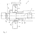
- FIG. 1 shows a switching device, which is designated in its entirety by 1.
- the switching device 1 can engage gears in a manual transmission.
- the switching device 1 comprises a switching shaft 2 with a longitudinal axis 3.
- the switching shaft 2 is displaceable along the longitudinal axis 3. In addition, it can be rotated around the longitudinal axis in the circumferential direction.
- the switching shaft 2 is formed here as a tubular body which is arranged coaxially to an inner shaft 4.
- a driver 5 which provides for a non-rotatable, but axially movable connection of the switching shaft 2 and tube body and inner shaft 4. On the interaction of shift shaft 2 and inner shaft 4 will be discussed later.
- a first detent element in the form of a ball 10 presses against a first detent contour 11.
- the detent contour 11 is fastened to the selector shaft 2, so that an axial displacement of the selector shaft 2 leads to a likewise in the same direction axial displacement of the detent contour 11.
- the first locking element or the ball 10 is pressed with a force F 1 against the locking contour 11.
- the first force F 1 should be the force of a coil spring (not shown) with an end face on the first locking element 10 is present.
- FIG. 1 is also a force F 1R located , which should represent the reaction force acting on the selector shaft 2 by the first force F 1 .
- the reaction force F 1R falls in terms of magnitude and in terms of direction with the first force F 1 together.
- a detent in the circumferential direction that is, when the switching shaft 2 is to be rotated about its longitudinal axis 3, the interaction of a second locking element 20 and a second locking contour 21.
- the second locking element 20 in the form of a ball is held by a detent 22.
- a arranged within the detent 22 coil spring pushes the second locking element 20 with a force F 2 against the detent 21.
- the force F 2 causes a reaction force, a so-called second reaction force F 2R , which presses against the switching shaft 2.
- Due to the opposite arranged Arrangement of detent 12 and detent 22 cancel the forces acting on the switching shaft 2 reaction forces F 1R and F 2R completely, provided that their amounts are the same and they are exactly offset by 180 °.
- the second locking contour 21 is arranged stationary relative to the switching shaft 2.
- the locking contour 21 is designed so that at least in a rotational angle of the switching shaft 2, the force F 2 undergoes a local minimum, which is then defined by the interaction of the second locking element 20 and locking contour 21, a detent position in the circumferential direction.
- FIG. 1 It can also be seen that an effective effective radius R 1 of the first latching contour 11 is significantly smaller than a mean effective radius R 2 of the second latching contour 21.
- the quotient R 2 / R 1 is in the embodiment of FIG. 1 about 3.
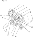
- FIG. 2 shows the switching device 1 in a perspective view.
- a movement of a shift lever 30 leads to an axial displacement of the shift shaft 2.
- a movement of a shift lever 31 ensures that the inner shaft 4 and via the driver 5, the shift shaft 2 and the tubular body rotates.
- FIG. 2 shows the driver 5, FIG. 2 However, does not show the recess in the tubular body in which the driver 5 is seated free of play in the circumferential direction, so that a rotation of the inner shaft leads to a rotation of the tubular body 2.
- FIG. 2 Rather, by a cut-away section in the tubular body 2, the inner shaft 4 and the driver 5 free. The cut-away section does not correspond to the recess in which the driver 5 is seated.
- the power flow from the shift lever 31 to the shift shaft 2 takes place, as already stated above, by the inner shaft 4 and the driver 5. If the shift lever 30 is actuated, only shift shaft 2 shifts in the axial direction, whereas the inner shaft 4 does not change its axial position changes. If the shift shaft 2 or the tubular body axially strigode or rotated (via the inner shaft 4), so moves according to a provided on the circumference of the tubular body shift finger 6. This shift finger 6, depending on the axial position in different shift forks (not shown). By rotating the tubular body can then move the engaged shift fork, whereby a gear of the gearbox can be inserted.
- the shift device 1 further comprises an inner shift gate 40 with four shift gates 41.
- a shift pin 41 engages the inner shift gate 41 and is located in an outer shift gate 41d. By rotation of the switching shaft 2, the switching pin 42 moves within this shift gate 41d. The end positions of the shift pin 42 in the shift gate 41d then correspond to engaged gears of the gearbox.
Landscapes
- Engineering & Computer Science (AREA)
- General Engineering & Computer Science (AREA)
- Mechanical Engineering (AREA)
- Gear-Shifting Mechanisms (AREA)
Claims (9)
- Dispositif de commutation (1) pour un engrenage, comprenant- un arbre de commutation (2) avec un axe longitudinal (3), dans lequel l'arbre de commutation (2) peut être déplacé le long de l'axe longitudinal (3) dans le sens axial et peut être tourné autour de l'axe longitudinal (3) dans le sens périphérique,- un premier élément d'encliquetage (10) et un premier contour d'encliquetage (11), dans lequel une première force presse le premier élément d'encliquetage (10) contre le premier contour d'encliquetage (11) et ainsi l'arbre de commutation (2) est maintenu dans au moins une position d'encliquetage axiale,- un second élément d'encliquetage (20) et un second contour d'encliquetage (21), dans lequel une seconde force presse le second élément d'encliquetage (20) contre le second contour d'encliquetage (21) et ainsi l'arbre de commutation (2) est maintenu dans au moins une position d'encliquetage dans le sens périphérique,dans lequel la première force provoque une première force de réaction agissant sur l'arbre de commutation (2) et la seconde force provoque une seconde force de réaction agissant sur l'arbre de commutation (2), dans lequel la première force de réaction et la seconde force de réaction s'annulent au moins partiellement dans le sens radial,
caractérisé en ce qu'un quotient d'un rayon actif médian du second contour d'encliquetage (21) et d'un rayon actif médian du premier contour d'encliquetage (11) est inférieur à 0,8 ou supérieur à 1,2, dans lesquels le rayon actif médian du premier contour d'encliquetage constitue une valeur médiane des distances des points de contact entre le premier élément d'encliquetage (10) et le premier contour d'encliquetage (11), par rapport à l'axe longitudinal (3) de l'arbre de commutation (2), qui peuvent résulter pour des positions axiales différentes de l'arbre de commutation (2), et dans lequel le rayon actif médian du second contour d'encliquetage constitue une valeur médiane des distances des points de contact entre le second élément d'encliquetage (20) et le second contour d'encliquetage (21), par rapport à l'axe longitudinal (3) de l'arbre de commutation (2), qui peuvent résulter pour des positions différentes de l'arbre de commutation (2) dans le sens périphérique. - Dispositif de commutation (1) selon la revendication 1, caractérisé en ce que le quotient est supérieur à 2.
- Dispositif de commutation (1) selon la revendication 1 ou 2, caractérisé en ce que le second contour d'encliquetage (21) est agencé fixement.
- Dispositif de commutation (1) selon l'une quelconque des revendications 1 à 3, caractérisé en ce que le premier contour d'encliquetage (10) se déplace au moins dans le sens axial avec l'arbre de commutation (2).
- Dispositif de commutation (1) selon l'une quelconque des revendications 1 à 4, caractérisé en ce que la première force agissant sur le premier élément d'encliquetage (10) et la seconde force agissant sur le second élément d'encliquetage (20) se trouvent dans un plan s'étendant perpendiculairement à l'axe longitudinal (3).
- Dispositif de commutation (1) selon l'une quelconque des revendications 1 à 5, caractérisé en ce que la première force de réaction et la seconde force de réaction sont décalées dans le sens périphérique et agissent avec un angle périphérique inclus de 160 à 180 degrés sur l'arbre de commutation.
- Dispositif de commutation (1) selon l'une quelconque des revendications 1 à 6, caractérisé en ce qu'une voie de commutation peut être sélectionnée par un déplacement axial de l'arbre de commutation (2) et une vitesse d'engrenage peut être introduite par une rotation.
- Dispositif de commutation (1) selon l'une quelconque des revendications 1 à 7, caractérisé en ce que l'arbre de commutation (2) est réalisé en tant que corps tubulaire qui entoure un arbre intérieur (4).
- Dispositif de commutation (1) selon la revendication 8, caractérisé en ce que l'arbre intérieur (4) présente un entraîneur (5) qui loge sensiblement sans jeu dans un évidement du corps tubulaire dans le sens périphérique et est agencé de manière mobile dans le sens axial.
Applications Claiming Priority (2)
| Application Number | Priority Date | Filing Date | Title |
|---|---|---|---|
| DE102011057148 | 2011-12-29 | ||
| DE102012100870.1A DE102012100870B4 (de) | 2011-12-29 | 2012-02-02 | Schaltvorrichtung für ein Schaltgetriebe |
Publications (3)
| Publication Number | Publication Date |
|---|---|
| EP2610531A2 EP2610531A2 (fr) | 2013-07-03 |
| EP2610531A3 EP2610531A3 (fr) | 2013-07-24 |
| EP2610531B1 true EP2610531B1 (fr) | 2019-09-18 |
Family
ID=47429621
Family Applications (1)
| Application Number | Title | Priority Date | Filing Date |
|---|---|---|---|
| EP12196411.8A Ceased EP2610531B1 (fr) | 2011-12-29 | 2012-12-11 | Dispositif de commande pour une boîte de vitesses |
Country Status (3)
| Country | Link |
|---|---|
| EP (1) | EP2610531B1 (fr) |
| CN (1) | CN103185136B (fr) |
| DE (1) | DE102012100870B4 (fr) |
Families Citing this family (5)
| Publication number | Priority date | Publication date | Assignee | Title |
|---|---|---|---|---|
| DE112015001436A5 (de) * | 2014-03-26 | 2016-12-08 | Schaeffler Technologies AG & Co. KG | Verfahren zur Bestimmung eines Betriebsmodus eines Getriebeaktors mit genau einem Motor |
| CN104033585B (zh) * | 2014-05-28 | 2016-04-27 | 浙江一铭机车部件有限公司 | 一种用于汽车变速箱的换档轴总成 |
| JP6471609B2 (ja) * | 2015-05-25 | 2019-02-20 | スズキ株式会社 | 手動変速機のシフト装置 |
| JP6384402B2 (ja) * | 2015-05-25 | 2018-09-05 | スズキ株式会社 | 手動変速機のシフト装置 |
| DE102015009036A1 (de) * | 2015-07-11 | 2017-01-12 | GM Global Technology Operations LLC (n. d. Gesetzen des Staates Delaware) | Schaltelement, insbesondere Schaltwelle oder Schaltanlage, für ein Getriebe |
Family Cites Families (11)
| Publication number | Priority date | Publication date | Assignee | Title |
|---|---|---|---|---|
| DE19610104C2 (de) * | 1996-03-15 | 1999-07-01 | Daimler Chrysler Ag | Schaltvorrichtung für ein Zahnräderwechselgetriebe sowie Verfahren zum Steuern dafür |
| DE19911662A1 (de) * | 1999-03-16 | 2000-09-21 | Volkswagen Ag | Rastvorrichtung |
| DE10020451C1 (de) * | 2000-04-26 | 2001-10-25 | Daimler Chrysler Ag | Schaltvorrichtung für ein Zahnräderwechselgetriebe |
| FR2884888B1 (fr) * | 2005-04-26 | 2007-08-03 | Peugeot Citroen Automobiles Sa | Dispositif de commande de boite de vitesses pour vehicule automobile |
| DE102005040704A1 (de) * | 2005-08-27 | 2007-03-08 | Schaeffler Kg | Übertragungselement mit zur Übertragung von Betätigungsbewegungen |
| EP2143979B1 (fr) * | 2008-05-13 | 2012-02-08 | Magneti Marelli S.p.A. | Dispositif de changement de vitesses pour boîte à double embrayages |
| DE102009058023A1 (de) * | 2008-12-19 | 2010-07-01 | Schaeffler Technologies Gmbh & Co. Kg | Schalteinheit eines Kraftfahrzeugschaltgetriebes |
| DE102009019250A1 (de) * | 2009-04-30 | 2010-11-11 | Koki Technik Transmission Systems Gmbh | Rastiervorrichtung, insbesondere für eine Schaltwelle |
| DE102009030823A1 (de) * | 2009-06-26 | 2011-01-20 | Koki Technik Transmission Systems Gmbh | Rastiervorrichtung für eine Schaltwelle |
| DE102010034228A1 (de) * | 2010-08-07 | 2011-05-12 | Daimler Ag | Schaltvorrichtung für ein Getriebe |
| AT509999B1 (de) * | 2010-09-08 | 2012-01-15 | Stiwa Holding Gmbh | Schaltanordnung sowie ein damit ausgestattetes zahnräderwechselgetriebe |
-
2012
- 2012-02-02 DE DE102012100870.1A patent/DE102012100870B4/de not_active Expired - Fee Related
- 2012-12-11 EP EP12196411.8A patent/EP2610531B1/fr not_active Ceased
- 2012-12-28 CN CN201210592066.5A patent/CN103185136B/zh not_active Expired - Fee Related
Non-Patent Citations (1)
| Title |
|---|
| None * |
Also Published As
| Publication number | Publication date |
|---|---|
| CN103185136B (zh) | 2017-03-01 |
| DE102012100870B4 (de) | 2014-07-31 |
| DE102012100870A1 (de) | 2013-07-04 |
| CN103185136A (zh) | 2013-07-03 |
| EP2610531A3 (fr) | 2013-07-24 |
| EP2610531A2 (fr) | 2013-07-03 |
Similar Documents
| Publication | Publication Date | Title |
|---|---|---|
| EP0731885B1 (fr) | Dispositif de changement de vitesse | |
| DE2839457C2 (fr) | ||
| DE2031654B2 (de) | Drehmomentübertragende Verbindung, insbesondere in einem Planetenräderwechselgetriebe | |
| EP2610531B1 (fr) | Dispositif de commande pour une boîte de vitesses | |
| DE3150885C2 (fr) | ||
| EP0975904A1 (fr) | Boite de vitesses avec arbre de selection central | |
| WO2010000590A1 (fr) | Dispositif de commande pour une boîte de vitesses de véhicule à moteur | |
| EP2046613A1 (fr) | Dispositif de levage | |
| EP2576134B1 (fr) | Tourelle revolver | |
| DE10206212A1 (de) | Kraftfahrzeug | |
| DE102009027438A1 (de) | Synchronisierung für ein Schaltgetriebe | |
| DE102021003333B3 (de) | Getriebevorrichtung mit einer Welle | |
| WO2017071993A1 (fr) | Dispositif de changement de vitesses et unité d'entraînement pour un véhicule automobile | |
| EP1956273B1 (fr) | Dispositif de passage doté d'un dispositif à ressort pour boîte de vitesses | |
| DE102006060535A1 (de) | Synchronisiereinrichtung für ein Schaltgetriebe | |
| AT519200B1 (de) | Klauenkupplungsvorrichtung | |
| DE102008045848A1 (de) | Planetengetriebe | |
| DE19536715C2 (de) | Schrittschalteinrichtung für ein Schaltgetriebe, insbesondere für Fahrzeuggetriebe | |
| WO2014059981A1 (fr) | Dispositif de changement de vitesse d'une boîte de vitesses de véhicule à moteur | |
| EP2619485A1 (fr) | Ensemble embrayage pour une transmission à engrenage | |
| EP3685063B1 (fr) | Unité de synchronisation | |
| DE102021128170A1 (de) | Klauenschaltung und Verfahren zum Schalten einer Klauenschaltung | |
| DE102016224001A1 (de) | Schaltvorrichtung eines Schaltgetriebes | |
| EP1966502A1 (fr) | Dispositif de synchronisation et bague de synchronisation pour dispositif de synchronisation | |
| EP0949434B1 (fr) | Transmission à vis |
Legal Events
| Date | Code | Title | Description |
|---|---|---|---|
| PUAL | Search report despatched |
Free format text: ORIGINAL CODE: 0009013 |
|
| PUAI | Public reference made under article 153(3) epc to a published international application that has entered the european phase |
Free format text: ORIGINAL CODE: 0009012 |
|
| AK | Designated contracting states |
Kind code of ref document: A2 Designated state(s): DE FR GB |
|
| AX | Request for extension of the european patent |
Extension state: BA ME |
|
| AK | Designated contracting states |
Kind code of ref document: A3 Designated state(s): DE FR GB |
|
| AX | Request for extension of the european patent |
Extension state: BA ME |
|
| RIC1 | Information provided on ipc code assigned before grant |
Ipc: F16H 61/24 20060101ALN20130619BHEP Ipc: F16H 63/38 20060101AFI20130619BHEP |
|
| 17P | Request for examination filed |
Effective date: 20140124 |
|
| RBV | Designated contracting states (corrected) |
Designated state(s): DE FR GB |
|
| REG | Reference to a national code |
Ref country code: DE Ref legal event code: R079 Ref document number: 502012015301 Country of ref document: DE Free format text: PREVIOUS MAIN CLASS: F16H0063380000 Ipc: F16H0061240000 |
|
| RIC1 | Information provided on ipc code assigned before grant |
Ipc: F16H 63/30 20060101ALN20190314BHEP Ipc: F16H 63/38 20060101ALN20190314BHEP Ipc: F16H 61/24 20060101AFI20190314BHEP |
|
| GRAP | Despatch of communication of intention to grant a patent |
Free format text: ORIGINAL CODE: EPIDOSNIGR1 |
|
| STAA | Information on the status of an ep patent application or granted ep patent |
Free format text: STATUS: GRANT OF PATENT IS INTENDED |
|
| INTG | Intention to grant announced |
Effective date: 20190515 |
|
| GRAS | Grant fee paid |
Free format text: ORIGINAL CODE: EPIDOSNIGR3 |
|
| GRAA | (expected) grant |
Free format text: ORIGINAL CODE: 0009210 |
|
| STAA | Information on the status of an ep patent application or granted ep patent |
Free format text: STATUS: THE PATENT HAS BEEN GRANTED |
|
| AK | Designated contracting states |
Kind code of ref document: B1 Designated state(s): DE FR GB |
|
| REG | Reference to a national code |
Ref country code: GB Ref legal event code: FG4D Free format text: NOT ENGLISH |
|
| REG | Reference to a national code |
Ref country code: DE Ref legal event code: R096 Ref document number: 502012015301 Country of ref document: DE |
|
| REG | Reference to a national code |
Ref country code: DE Ref legal event code: R097 Ref document number: 502012015301 Country of ref document: DE |
|
| PLBE | No opposition filed within time limit |
Free format text: ORIGINAL CODE: 0009261 |
|
| STAA | Information on the status of an ep patent application or granted ep patent |
Free format text: STATUS: NO OPPOSITION FILED WITHIN TIME LIMIT |
|
| 26N | No opposition filed |
Effective date: 20200619 |
|
| PGFP | Annual fee paid to national office [announced via postgrant information from national office to epo] |
Ref country code: GB Payment date: 20221222 Year of fee payment: 11 Ref country code: FR Payment date: 20221219 Year of fee payment: 11 |
|
| PGFP | Annual fee paid to national office [announced via postgrant information from national office to epo] |
Ref country code: DE Payment date: 20221227 Year of fee payment: 11 |
|
| REG | Reference to a national code |
Ref country code: DE Ref legal event code: R119 Ref document number: 502012015301 Country of ref document: DE |
|
| GBPC | Gb: european patent ceased through non-payment of renewal fee |
Effective date: 20231211 |
|
| PG25 | Lapsed in a contracting state [announced via postgrant information from national office to epo] |
Ref country code: DE Free format text: LAPSE BECAUSE OF NON-PAYMENT OF DUE FEES Effective date: 20240702 |
|
| PG25 | Lapsed in a contracting state [announced via postgrant information from national office to epo] |
Ref country code: GB Free format text: LAPSE BECAUSE OF NON-PAYMENT OF DUE FEES Effective date: 20231211 |
|
| PG25 | Lapsed in a contracting state [announced via postgrant information from national office to epo] |
Ref country code: FR Free format text: LAPSE BECAUSE OF NON-PAYMENT OF DUE FEES Effective date: 20231231 |
|
| PG25 | Lapsed in a contracting state [announced via postgrant information from national office to epo] |
Ref country code: GB Free format text: LAPSE BECAUSE OF NON-PAYMENT OF DUE FEES Effective date: 20231211 Ref country code: FR Free format text: LAPSE BECAUSE OF NON-PAYMENT OF DUE FEES Effective date: 20231231 Ref country code: DE Free format text: LAPSE BECAUSE OF NON-PAYMENT OF DUE FEES Effective date: 20240702 |