EP2610566A2 - Zweitürige Kühlvorrichtung - Google Patents
Zweitürige Kühlvorrichtung Download PDFInfo
- Publication number
- EP2610566A2 EP2610566A2 EP12198433.0A EP12198433A EP2610566A2 EP 2610566 A2 EP2610566 A2 EP 2610566A2 EP 12198433 A EP12198433 A EP 12198433A EP 2610566 A2 EP2610566 A2 EP 2610566A2
- Authority
- EP
- European Patent Office
- Prior art keywords
- guiding
- bar
- door
- projection
- groove
- Prior art date
- Legal status (The legal status is an assumption and is not a legal conclusion. Google has not performed a legal analysis and makes no representation as to the accuracy of the status listed.)
- Granted
Links
Images


Classifications
-
- F—MECHANICAL ENGINEERING; LIGHTING; HEATING; WEAPONS; BLASTING
- F25—REFRIGERATION OR COOLING; COMBINED HEATING AND REFRIGERATION SYSTEMS; HEAT PUMP SYSTEMS; MANUFACTURE OR STORAGE OF ICE; LIQUEFACTION SOLIDIFICATION OF GASES
- F25D—REFRIGERATORS; COLD ROOMS; ICE-BOXES; COOLING OR FREEZING APPARATUS NOT OTHERWISE PROVIDED FOR
- F25D23/00—General constructional features
- F25D23/02—Doors; Covers
- F25D23/028—Details
-
- F—MECHANICAL ENGINEERING; LIGHTING; HEATING; WEAPONS; BLASTING
- F25—REFRIGERATION OR COOLING; COMBINED HEATING AND REFRIGERATION SYSTEMS; HEAT PUMP SYSTEMS; MANUFACTURE OR STORAGE OF ICE; LIQUEFACTION SOLIDIFICATION OF GASES
- F25D—REFRIGERATORS; COLD ROOMS; ICE-BOXES; COOLING OR FREEZING APPARATUS NOT OTHERWISE PROVIDED FOR
- F25D2323/00—General constructional features not provided for in other groups of this subclass
- F25D2323/02—Details of doors or covers not otherwise covered
- F25D2323/021—French doors
Definitions
- the present invention relates to a refrigeration appliance comprising two doors, in particular a domestic refrigeration appliance, such as a refrigerator.
- WO2007/115868 discloses a refrigeration device, comprising a body, a pair of side-by-side doors connected to opposite sides of the body and a bar rotatably connected on a first door.
- the bar can be pivoted between an extension position and a retraction position by a guiding projection capable of displacing in a guiding groove, wherein the bar is in the extension position when the first door is closed, and the bar is in the retraction position when the door is opened.
- a guiding projection capable of displacing in a guiding groove
- the guiding projection can displace with respect to the first door in a direction of a pivot axis of the first door. Thus, it may be ensured that a top end of the guiding projection contact with a bottom of the guiding groove such that no air can enter an interior of the refrigeration device through the guiding projection.
- the bar may be rotated into the retraction position via a movement of the guiding projection within the guiding groove under cooperation of the guiding projection with the guiding groove, there is such a possibility in which the bar may be unintentionally rotated into the extension position by a user.
- the guiding projection may be rebounded due to intensive collision of the guiding projection with a groove wall defining the guiding groove, which may lead to damage of the refrigeration appliance.
- one aspect of the present invention relates to a refrigeration appliance, comprising: a body, a front end of which has an opening; a first door and a second door each comprising a first edge and a second edge opposite to said first edge, the first edges of the first door and the second door being fixed to opposite sides of said opening respectively; a bar fixed to the second edge of said first door and being able to be pivoted between a retraction position and an extension position, the bar being in the extension position when the first door is closed, wherein said bar can pass through the closed second door when the bar is in said retraction position; and a guiding mechanism for guiding said bar to rotate, said guiding mechanism comprising a first guiding member disposed on said bar and a second guiding member disposed on an edge of said opening, wherein one of said first guiding member and said second guiding member comprises a guiding projection, the other of said first guiding member and said second guiding member comprises a guiding groove, and said guiding projection can be moved within said guiding groove to cause said
- first guiding member and the second guiding member do not intensively collide with each other so as to cause damage when the first door is closed in the case that the bar is in the extension position, thereby it being beneficial to improve useful life of the refrigeration appliance.
- said bar and said first door define an angle therebetween, which keeps constant when said first door is closed in the case that said bar is in the extension position.
- said guiding projection is linearly moved with respect to said first door when said first door is closed in the case that said bar is in the extension position.
- said guiding projection extends over a groove wall of said guiding groove facing said guiding projection so as to enter said guiding groove.
- At least one of said guiding projection and said groove wall can be displaced with respect to said first door along a direction of a pivot axis of said first door.
- at least one of the guiding projection and the groove wall can be moved away from each other when the guiding projection and the groove wall contact with each other. Further, this benefits return of the displaceable member to an initial position to prevent the guiding projection within the groove wall from moving away from the groove wall after the contact between the guiding projection and the groove wall has been released.
- a tip face of at least one of said guiding projection and said groove wall has a guiding slope, and a height of said guiding projection and/or said groove wall at respective guiding slope become smaller while getting closer to each other.
- the entire tip face of at least one of said guiding projection and said groove wall forms said guiding slope. This may cause the guiding projection to more easily extend over the groove wall to enter the guiding groove.
- said guiding slope has a plurality of protuberances. This benefits reduction of a friction force between the guiding projection and the groove wall.
- said protuberances comprise ribs extending along an inclination direction of said guiding slope.
- said guiding projection is rotated along the guiding groove and causes said bar to rotate into the retraction position, which cause the bar to automatically arrive in the retraction position after the first door is opened, thereby, in a normal condition, it is possible to close the first door by rotating the guiding projection along the guiding groove.
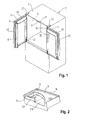
- a refrigeration appliance 1 comprises a heat insulation body 2, a left door 4 and a right door 5 fixed to two opposite sides of the body 2.
- the body 2 defines a refrigeration chamber 20 with a front opening 3.
- the left door 4 and the right door 5 are connected to a front side of the body 2, in order to selectively open or close the refrigeration chamber 20.
- the left door 4 and the right door 5 are each fixed on the body 2 by respective hinge units 22 so as to be capable of rotating around respective longitudinal axes.
- Fig. 1 the left door 4 and the right door 5 are shown in an open position.
- the left door 4 comprises a first edge 41 fixed to a left side of the opening 3 and a second edge 42 opposite to the first edge 41
- the right door 5 comprises a first edge 51 fixed to a right side of the opening 3 and a second edge 52 opposite to the first edge 51.
- the refrigeration appliance 1 For closing the gap, the refrigeration appliance 1 has a bar 6 fixed to the second edge 42 of the left door 4. It should be understood that the bar 6 may also be fixed to the right door 5.
- the bar 6 is pivoted to the left door 4 so as to be capable of rotating around a vertical axis (not shown).
- the bar 6 can be pivoted between an extension position and a retraction position.
- the bar 6 having a rectangular cross section is retracted such that its narrow side faces the body 2.
- the bar 6 does not extend beyond the second edge 42 of the left door 4.
- the bar 6 in a close state of the right door 5, the bar 6 can extend over the right door 5 if the left door 4 is closed.
- the bar 6 snaps into an interior of the body 2 and is rotated around the vertical axis during the process, such that a joint face 61 formed at a wide side of the bar 6 is flush with a front end face of a frame 21 of the body 2 after the bar 6 snaps into the body 2, and then the bar 6 is in the extension position, wherein the front end face can rest against seal gaskets 43, 53 of the left door 4 and the right door 5 in the close state.
- the frame 21 and the joint face 61 form a joint surface capable of covering the gap between the left door 4 and the right door 5, and the seal gaskets 43, 53 of the left door 4 and the right door 5 rest against said joint surface in a sealing manner.
- the refrigeration appliance 1 comprises a guiding mechanism 7 for guiding the bar 6 to rotate.
- the guiding mechanism 7 comprises a first guiding member 8 disposed on at least one end of the bar 6 and a second guiding member 9 disposed at an edge of the opening 3.
- the first guiding member 8 and the second guiding member 9 are provided only on an upper end of the bar 6 and an upper edge of the opening 3 respectively.
- the guiding mechanism may also be provided between a lower end of the bar 6 and a lower edge of the opening 3. It is also possible to provide the guiding mechanism between two respective ends of the bar 6 and the body 2.
- the first guiding member 8 comprises a guiding projection 10
- the second guiding member 9 comprises a guiding groove 11.
- the guiding projection 10 can be moved within the guiding groove 11 to cause the bar 6 to rotate.
- the guiding projection 10 has an arcuate cross section.
- the guiding projection 10 can be moved with respect to the left door 4 along a direction of the pivot axis of the left door 4, and this means that the guiding projection 10 can be moved in a longitudinal direction in the present embodiment.
- the guiding projection 10 can be moved with respect to the bar 6.
- a cutout 63 for receiving the guiding projection 10 may be disposed at the end of the bar 6, and the guiding projection 10 is guided in the cutout 63 in a manner that it can be displaced vertically.
- a sleeve 102 is provided at an inside of the guiding projection 10 and the sleeve 102 surrounds a pin 62 located within the bar 6.
- the guiding mechanism 7 also comprises a coil spring 71 located on the pin 62, in order to support the guiding projection 10. The coil spring 71 can push the guiding projection 10 upward when no external force is applied.
- a tip face of the guiding projection 10 forms a first guiding slope 101.
- a height of the guiding projection 10 at the respective first guiding slope 101 is smaller as it is closer to a rear face 64 facing away from the joint face 61, such that an edge of the tip face of the guiding projection 10 closest to the rear face 64 has a minimum height.
- the guiding projection 10 has the minimum height at an edge thereof closest to the second guiding member 9.
- the guiding groove 11 of the second guiding member 9 has a curved shape.
- the guiding groove 11 has an inlet 110 facing the first guiding member 8.
- the second guiding member 9 comprises a first groove wall 12 facing the first guiding member 8 and a second groove wall 14 facing away from the first guiding member 8.
- the first groove wall 12 is in front of the guiding groove 11, and the second groove wall 14 is behind the guiding groove 11.
- a tip face of the first groove wall 12 has a second guiding slope 122 corresponding to the first guiding slope 101.
- a height of the first groove wall 12 at the respective second guiding slope 122 is smaller as it is closer to the guiding projection 10, such that the height of the first groove wall 12 at a front edge of the respective tip face is minimum.
- the first groove wall 12 has a minimum height at an edge closest to the guiding projection 10 in the direction perpendicular to the frame 21/the joint face 61.
- the left door 4 can be opened in the case of a closed state of the right door 5.
- the bar 6 may automatically be rotated into the retraction position so as to not interfere with the right door 5. However, the bar 6 may unintentionally be rotated into the extension position due to misoperation of a user.
- the guiding projection 10 can also enter the guiding groove 11 to close the left door 4 even though the bar 6 is in the extension position.
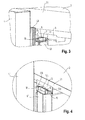
- Figs 4-7 schematically shows closing process of the left door 4 when the bar 6 is in the extension position.
- the guiding slope 101 of the guiding projection 10 is slightly lower at a side close to the body 2 than the most front side of the tip face of the first groove wall 12 in the longitudinal direction, thus the guiding slope 101 and the first groove wall 12 overlap each other in the longitudinal direction. If the left door 4 is further pushed, the tip face of the guiding projection 10 and the tip face of the first groove wall 12 contact with and press each other so as to compress the spring 71, therefore, the guiding projection 10 supported by the spring 71 move downward, as shown in Fig. 6 .
- the guiding projection 10 has extended over the first groove wall 12 and entered the guiding groove 11. After the contact and press between the guiding projection 10 and the first groove wall 12 has been released, the guiding projection 10 is moved toward a bottom wall of the guiding groove 11 under a support force of the spring 71.
- the guiding projection 10 and the first groove wall 12 overlap each other in the direction perpendicular to the joint face 61, in order to prevent the guiding projection 10 from extending over the first groove wall 12 to exit the guiding groove 11.
- the first guiding slope 101 is provided with a plurality of protuberances 13.
- the protuberances 13 may be formed by ribs extending in a slope direction of the first guiding slope 101. In an alternative embodiment, the protuberances 13 may also be provided on the second guiding slope 122.
- a wear resistant layer for reducing wear may also be provided on the tip face of the guiding projection 10 and the tip face of the first groove wall 12.
- the entire tip face of the guiding projection 10 forms the first guiding slope 101.
- the first guiding slope 101 may also be formed by a part of the tip face of the guiding projection 10.
- the second guiding slope 121 may also be formed by the entire tip face of the first groove wall 12 or a part of the tip face of the first groove wall 12.
- the guiding projection 10 may be moved along the direction of the pivot axis of the left door 4 under the support force of the spring 17.
- the entire guiding member provided with the guiding groove or only the first groove wall therein can be moved in the vertical direction under a support force of a spring such that the bar in the extension position can extend over the first groove wall to be translationally pushed into the guiding groove.
- the first guiding member 8 mounted on the bar 6 is provided with the guiding projection 10, while the second guiding member 9 on the body 2 is provided with the guiding groove 11 adapted to cooperate with the guiding projection 10.
- the present invention is not limited to this, but there are also other embodiments.
- the guiding groove is disposed on the guiding member on the bar, while the guiding projection adapted to cooperate with the guiding groove is provided on the body.
Landscapes
- Engineering & Computer Science (AREA)
- Chemical & Material Sciences (AREA)
- Combustion & Propulsion (AREA)
- Physics & Mathematics (AREA)
- Mechanical Engineering (AREA)
- Thermal Sciences (AREA)
- General Engineering & Computer Science (AREA)
- Refrigerator Housings (AREA)
- Cold Air Circulating Systems And Constructional Details In Refrigerators (AREA)
Applications Claiming Priority (1)
| Application Number | Priority Date | Filing Date | Title |
|---|---|---|---|
| CN201110461228.7A CN103185441B (zh) | 2011-12-30 | 2011-12-30 | 包括两个门的制冷电器 |
Publications (3)
| Publication Number | Publication Date |
|---|---|
| EP2610566A2 true EP2610566A2 (de) | 2013-07-03 |
| EP2610566A3 EP2610566A3 (de) | 2017-11-29 |
| EP2610566B1 EP2610566B1 (de) | 2019-08-28 |
Family
ID=47603060
Family Applications (1)
| Application Number | Title | Priority Date | Filing Date |
|---|---|---|---|
| EP12198433.0A Active EP2610566B1 (de) | 2011-12-30 | 2012-12-20 | Zweitürige Kühlvorrichtung |
Country Status (2)
| Country | Link |
|---|---|
| EP (1) | EP2610566B1 (de) |
| CN (1) | CN103185441B (de) |
Cited By (6)
| Publication number | Priority date | Publication date | Assignee | Title |
|---|---|---|---|---|
| CN103542677A (zh) * | 2013-10-31 | 2014-01-29 | 合肥美的电冰箱有限公司 | 用于冰箱的翻转梁和具有其的冰箱 |
| CN104236226A (zh) * | 2014-10-11 | 2014-12-24 | 合肥美的电冰箱有限公司 | 冰箱的门体 |
| WO2016192972A1 (en) * | 2015-06-04 | 2016-12-08 | Arcelik Anonim Sirketi | A refrigerator with increased insulation efficiency |
| US20180179792A1 (en) * | 2015-09-11 | 2018-06-28 | Lg Electronics Inc. | Refrigerator |
| US10775095B2 (en) * | 2016-01-14 | 2020-09-15 | Lg Electronics Inc. | Refrigerator |
| US20240318896A1 (en) * | 2021-12-23 | 2024-09-26 | Samsung Electronics Co., Ltd. | Refrigerator |
Families Citing this family (14)
| Publication number | Priority date | Publication date | Assignee | Title |
|---|---|---|---|---|
| CN104279823A (zh) * | 2014-10-24 | 2015-01-14 | 合肥美的电冰箱有限公司 | 冰箱门体组件和冰箱 |
| CN104534796A (zh) * | 2014-12-23 | 2015-04-22 | 合肥美的电冰箱有限公司 | 冰箱及其翻转梁组件 |
| CN105202856B (zh) * | 2015-10-14 | 2018-02-02 | 青岛海尔股份有限公司 | 冰箱 |
| CN106855332B (zh) * | 2015-12-09 | 2021-02-09 | 博西华电器(江苏)有限公司 | 制冷设备及其工作方法 |
| CN105890255B (zh) * | 2016-04-29 | 2018-05-11 | 合肥华凌股份有限公司 | 一种冰箱门及冰箱 |
| CN106052275A (zh) * | 2016-07-15 | 2016-10-26 | 合肥华凌股份有限公司 | 对开门冰箱及其冰箱翻转梁 |
| CN106152687B (zh) * | 2016-08-30 | 2018-12-14 | 青岛海尔股份有限公司 | 对开门冰箱及其竖梁导向装置 |
| CN106322901B (zh) * | 2016-09-09 | 2018-03-23 | 青岛海尔股份有限公司 | 对开门冰箱及其竖梁导向装置 |
| CN106524623B (zh) * | 2016-10-31 | 2018-04-20 | 青岛海尔股份有限公司 | 法式对开门冰箱及其竖梁导向装置 |
| CN106610167B (zh) * | 2016-11-28 | 2018-03-23 | 青岛海尔股份有限公司 | 法式对开门冰箱及其竖梁导向装置 |
| CN108968533A (zh) * | 2018-08-10 | 2018-12-11 | 昆山弘锦威电子有限公司 | 一种液晶显示屏半成品贮存装置 |
| KR20200021823A (ko) * | 2018-08-21 | 2020-03-02 | 주식회사 위니아대우 | 프렌치 도어 타입 냉장고 및 도어 실링 장치 |
| US10982897B2 (en) * | 2019-04-03 | 2021-04-20 | Haier Us Appliance Solutions, Inc. | Appliance having an articulating mullion and damping assembly |
| JP7542849B2 (ja) * | 2020-08-31 | 2024-09-02 | アクア株式会社 | 冷蔵庫 |
Citations (1)
| Publication number | Priority date | Publication date | Assignee | Title |
|---|---|---|---|---|
| WO2007115868A2 (de) | 2006-04-05 | 2007-10-18 | BSH Bosch und Siemens Hausgeräte GmbH | Kältegerät mit zwei türen |
Family Cites Families (7)
| Publication number | Priority date | Publication date | Assignee | Title |
|---|---|---|---|---|
| KR970004291Y1 (ko) * | 1992-11-09 | 1997-05-08 | 윤종용 | 냉장고의 냉기유출방지구조 |
| CA2438766C (en) * | 2003-08-29 | 2008-12-30 | Maytag Corporation | Refrigerator incorporating french doors with rotating mullion bar |
| KR100602218B1 (ko) * | 2004-12-28 | 2006-07-19 | 엘지전자 주식회사 | 플렌치도어 타입 냉장고의 냉장실도어 실링장치 |
| CN101135531B (zh) * | 2006-08-28 | 2010-10-13 | 海尔集团公司 | 具有活动中梁对开门的电冰箱 |
| US8167389B2 (en) * | 2008-09-25 | 2012-05-01 | Samsung Electronics Co., Ltd. | Refrigerator mullion with protection unit |
| KR20110032898A (ko) * | 2009-09-24 | 2011-03-30 | 엘지전자 주식회사 | 냉기 유출방지 부재를 갖는 냉장고 |
| CN102506547A (zh) * | 2011-11-22 | 2012-06-20 | 合肥美的荣事达电冰箱有限公司 | 冰箱 |
-
2011
- 2011-12-30 CN CN201110461228.7A patent/CN103185441B/zh active Active
-
2012
- 2012-12-20 EP EP12198433.0A patent/EP2610566B1/de active Active
Patent Citations (1)
| Publication number | Priority date | Publication date | Assignee | Title |
|---|---|---|---|---|
| WO2007115868A2 (de) | 2006-04-05 | 2007-10-18 | BSH Bosch und Siemens Hausgeräte GmbH | Kältegerät mit zwei türen |
Cited By (8)
| Publication number | Priority date | Publication date | Assignee | Title |
|---|---|---|---|---|
| CN103542677A (zh) * | 2013-10-31 | 2014-01-29 | 合肥美的电冰箱有限公司 | 用于冰箱的翻转梁和具有其的冰箱 |
| CN103542677B (zh) * | 2013-10-31 | 2015-10-21 | 合肥美的电冰箱有限公司 | 用于冰箱的翻转梁和具有其的冰箱 |
| CN104236226A (zh) * | 2014-10-11 | 2014-12-24 | 合肥美的电冰箱有限公司 | 冰箱的门体 |
| WO2016192972A1 (en) * | 2015-06-04 | 2016-12-08 | Arcelik Anonim Sirketi | A refrigerator with increased insulation efficiency |
| US20180179792A1 (en) * | 2015-09-11 | 2018-06-28 | Lg Electronics Inc. | Refrigerator |
| US11199033B2 (en) * | 2015-09-11 | 2021-12-14 | Lg Electronics Inc. | Refrigerator |
| US10775095B2 (en) * | 2016-01-14 | 2020-09-15 | Lg Electronics Inc. | Refrigerator |
| US20240318896A1 (en) * | 2021-12-23 | 2024-09-26 | Samsung Electronics Co., Ltd. | Refrigerator |
Also Published As
| Publication number | Publication date |
|---|---|
| CN103185441A (zh) | 2013-07-03 |
| EP2610566A3 (de) | 2017-11-29 |
| CN103185441B (zh) | 2016-09-07 |
| EP2610566B1 (de) | 2019-08-28 |
Similar Documents
| Publication | Publication Date | Title |
|---|---|---|
| EP2610566A2 (de) | Zweitürige Kühlvorrichtung | |
| US8474103B2 (en) | Door hinge | |
| KR101949738B1 (ko) | 냉장고용 레일 조립체 및 냉장고 | |
| CN103452414B (zh) | 门开关用支撑条 | |
| KR101030879B1 (ko) | 도어 자동닫힘장치를 구비한 가구 | |
| EP3026376A1 (de) | Aufbewahrungsboxanordnung und kühlschrank damit | |
| CN104075534B (zh) | 冰箱 | |
| US20090273262A1 (en) | Ejector of a moveable furniture part | |
| KR20210000434A (ko) | 냉장고 도어용 힌지 어셈블리 | |
| KR100602218B1 (ko) | 플렌치도어 타입 냉장고의 냉장실도어 실링장치 | |
| EP2713109B1 (de) | Gargerät mit einer Vorrichtung zum Verschließen eines Abzugs | |
| KR102873470B1 (ko) | 디스플레이 모듈을 포함하는 가전제품 | |
| US10612686B2 (en) | Safety faucet for hot water | |
| CN108106311B (zh) | 冰箱 | |
| CN205894867U (zh) | 把手组件和冰箱 | |
| RU2012150129A (ru) | Передняя панель для розетки | |
| EP2336689A2 (de) | Türgriff für Haushaltskühlvorrichtung | |
| EP3649414B1 (de) | Kühlschrank mit doppeltüren | |
| JP5784338B2 (ja) | 閉鎖機構付き丁番 | |
| JP6909296B2 (ja) | 扉開閉機構 | |
| KR102100191B1 (ko) | 냉장고 | |
| CN206890949U (zh) | 冰箱及其翻转梁 | |
| JP4827746B2 (ja) | 扉開閉機構 | |
| KR101390975B1 (ko) | 미닫이식 도어용 안전 손잡이 | |
| CN112212595B (zh) | 一种冰箱 |
Legal Events
| Date | Code | Title | Description |
|---|---|---|---|
| PUAI | Public reference made under article 153(3) epc to a published international application that has entered the european phase |
Free format text: ORIGINAL CODE: 0009012 |
|
| AK | Designated contracting states |
Kind code of ref document: A2 Designated state(s): AL AT BE BG CH CY CZ DE DK EE ES FI FR GB GR HR HU IE IS IT LI LT LU LV MC MK MT NL NO PL PT RO RS SE SI SK SM TR |
|
| AX | Request for extension of the european patent |
Extension state: BA ME |
|
| RAP1 | Party data changed (applicant data changed or rights of an application transferred) |
Owner name: BSH HAUSGERAETE GMBH |
|
| PUAL | Search report despatched |
Free format text: ORIGINAL CODE: 0009013 |
|
| AK | Designated contracting states |
Kind code of ref document: A3 Designated state(s): AL AT BE BG CH CY CZ DE DK EE ES FI FR GB GR HR HU IE IS IT LI LT LU LV MC MK MT NL NO PL PT RO RS SE SI SK SM TR |
|
| AX | Request for extension of the european patent |
Extension state: BA ME |
|
| RIC1 | Information provided on ipc code assigned before grant |
Ipc: F25D 23/02 20060101AFI20171023BHEP |
|
| STAA | Information on the status of an ep patent application or granted ep patent |
Free format text: STATUS: REQUEST FOR EXAMINATION WAS MADE |
|
| 17P | Request for examination filed |
Effective date: 20180529 |
|
| RBV | Designated contracting states (corrected) |
Designated state(s): AL AT BE BG CH CY CZ DE DK EE ES FI FR GB GR HR HU IE IS IT LI LT LU LV MC MK MT NL NO PL PT RO RS SE SI SK SM TR |
|
| GRAP | Despatch of communication of intention to grant a patent |
Free format text: ORIGINAL CODE: EPIDOSNIGR1 |
|
| STAA | Information on the status of an ep patent application or granted ep patent |
Free format text: STATUS: GRANT OF PATENT IS INTENDED |
|
| INTG | Intention to grant announced |
Effective date: 20190517 |
|
| GRAS | Grant fee paid |
Free format text: ORIGINAL CODE: EPIDOSNIGR3 |
|
| GRAA | (expected) grant |
Free format text: ORIGINAL CODE: 0009210 |
|
| STAA | Information on the status of an ep patent application or granted ep patent |
Free format text: STATUS: THE PATENT HAS BEEN GRANTED |
|
| AK | Designated contracting states |
Kind code of ref document: B1 Designated state(s): AL AT BE BG CH CY CZ DE DK EE ES FI FR GB GR HR HU IE IS IT LI LT LU LV MC MK MT NL NO PL PT RO RS SE SI SK SM TR |
|
| REG | Reference to a national code |
Ref country code: GB Ref legal event code: FG4D |
|
| REG | Reference to a national code |
Ref country code: CH Ref legal event code: EP |
|
| REG | Reference to a national code |
Ref country code: AT Ref legal event code: REF Ref document number: 1172918 Country of ref document: AT Kind code of ref document: T Effective date: 20190915 |
|
| REG | Reference to a national code |
Ref country code: IE Ref legal event code: FG4D |
|
| REG | Reference to a national code |
Ref country code: DE Ref legal event code: R096 Ref document number: 602012063337 Country of ref document: DE |
|
| REG | Reference to a national code |
Ref country code: NL Ref legal event code: MP Effective date: 20190828 |
|
| REG | Reference to a national code |
Ref country code: LT Ref legal event code: MG4D |
|
| PG25 | Lapsed in a contracting state [announced via postgrant information from national office to epo] |
Ref country code: HR Free format text: LAPSE BECAUSE OF FAILURE TO SUBMIT A TRANSLATION OF THE DESCRIPTION OR TO PAY THE FEE WITHIN THE PRESCRIBED TIME-LIMIT Effective date: 20190828 Ref country code: LT Free format text: LAPSE BECAUSE OF FAILURE TO SUBMIT A TRANSLATION OF THE DESCRIPTION OR TO PAY THE FEE WITHIN THE PRESCRIBED TIME-LIMIT Effective date: 20190828 Ref country code: PT Free format text: LAPSE BECAUSE OF FAILURE TO SUBMIT A TRANSLATION OF THE DESCRIPTION OR TO PAY THE FEE WITHIN THE PRESCRIBED TIME-LIMIT Effective date: 20191230 Ref country code: SE Free format text: LAPSE BECAUSE OF FAILURE TO SUBMIT A TRANSLATION OF THE DESCRIPTION OR TO PAY THE FEE WITHIN THE PRESCRIBED TIME-LIMIT Effective date: 20190828 Ref country code: BG Free format text: LAPSE BECAUSE OF FAILURE TO SUBMIT A TRANSLATION OF THE DESCRIPTION OR TO PAY THE FEE WITHIN THE PRESCRIBED TIME-LIMIT Effective date: 20191128 Ref country code: NL Free format text: LAPSE BECAUSE OF FAILURE TO SUBMIT A TRANSLATION OF THE DESCRIPTION OR TO PAY THE FEE WITHIN THE PRESCRIBED TIME-LIMIT Effective date: 20190828 Ref country code: FI Free format text: LAPSE BECAUSE OF FAILURE TO SUBMIT A TRANSLATION OF THE DESCRIPTION OR TO PAY THE FEE WITHIN THE PRESCRIBED TIME-LIMIT Effective date: 20190828 Ref country code: NO Free format text: LAPSE BECAUSE OF FAILURE TO SUBMIT A TRANSLATION OF THE DESCRIPTION OR TO PAY THE FEE WITHIN THE PRESCRIBED TIME-LIMIT Effective date: 20191128 |
|
| PG25 | Lapsed in a contracting state [announced via postgrant information from national office to epo] |
Ref country code: RS Free format text: LAPSE BECAUSE OF FAILURE TO SUBMIT A TRANSLATION OF THE DESCRIPTION OR TO PAY THE FEE WITHIN THE PRESCRIBED TIME-LIMIT Effective date: 20190828 Ref country code: IS Free format text: LAPSE BECAUSE OF FAILURE TO SUBMIT A TRANSLATION OF THE DESCRIPTION OR TO PAY THE FEE WITHIN THE PRESCRIBED TIME-LIMIT Effective date: 20191228 Ref country code: LV Free format text: LAPSE BECAUSE OF FAILURE TO SUBMIT A TRANSLATION OF THE DESCRIPTION OR TO PAY THE FEE WITHIN THE PRESCRIBED TIME-LIMIT Effective date: 20190828 Ref country code: AL Free format text: LAPSE BECAUSE OF FAILURE TO SUBMIT A TRANSLATION OF THE DESCRIPTION OR TO PAY THE FEE WITHIN THE PRESCRIBED TIME-LIMIT Effective date: 20190828 Ref country code: GR Free format text: LAPSE BECAUSE OF FAILURE TO SUBMIT A TRANSLATION OF THE DESCRIPTION OR TO PAY THE FEE WITHIN THE PRESCRIBED TIME-LIMIT Effective date: 20191129 Ref country code: ES Free format text: LAPSE BECAUSE OF FAILURE TO SUBMIT A TRANSLATION OF THE DESCRIPTION OR TO PAY THE FEE WITHIN THE PRESCRIBED TIME-LIMIT Effective date: 20190828 |
|
| REG | Reference to a national code |
Ref country code: AT Ref legal event code: MK05 Ref document number: 1172918 Country of ref document: AT Kind code of ref document: T Effective date: 20190828 |
|
| PG25 | Lapsed in a contracting state [announced via postgrant information from national office to epo] |
Ref country code: TR Free format text: LAPSE BECAUSE OF FAILURE TO SUBMIT A TRANSLATION OF THE DESCRIPTION OR TO PAY THE FEE WITHIN THE PRESCRIBED TIME-LIMIT Effective date: 20190828 |
|
| PG25 | Lapsed in a contracting state [announced via postgrant information from national office to epo] |
Ref country code: AT Free format text: LAPSE BECAUSE OF FAILURE TO SUBMIT A TRANSLATION OF THE DESCRIPTION OR TO PAY THE FEE WITHIN THE PRESCRIBED TIME-LIMIT Effective date: 20190828 Ref country code: DK Free format text: LAPSE BECAUSE OF FAILURE TO SUBMIT A TRANSLATION OF THE DESCRIPTION OR TO PAY THE FEE WITHIN THE PRESCRIBED TIME-LIMIT Effective date: 20190828 Ref country code: PL Free format text: LAPSE BECAUSE OF FAILURE TO SUBMIT A TRANSLATION OF THE DESCRIPTION OR TO PAY THE FEE WITHIN THE PRESCRIBED TIME-LIMIT Effective date: 20190828 Ref country code: IT Free format text: LAPSE BECAUSE OF FAILURE TO SUBMIT A TRANSLATION OF THE DESCRIPTION OR TO PAY THE FEE WITHIN THE PRESCRIBED TIME-LIMIT Effective date: 20190828 Ref country code: EE Free format text: LAPSE BECAUSE OF FAILURE TO SUBMIT A TRANSLATION OF THE DESCRIPTION OR TO PAY THE FEE WITHIN THE PRESCRIBED TIME-LIMIT Effective date: 20190828 Ref country code: RO Free format text: LAPSE BECAUSE OF FAILURE TO SUBMIT A TRANSLATION OF THE DESCRIPTION OR TO PAY THE FEE WITHIN THE PRESCRIBED TIME-LIMIT Effective date: 20190828 |
|
| PG25 | Lapsed in a contracting state [announced via postgrant information from national office to epo] |
Ref country code: SM Free format text: LAPSE BECAUSE OF FAILURE TO SUBMIT A TRANSLATION OF THE DESCRIPTION OR TO PAY THE FEE WITHIN THE PRESCRIBED TIME-LIMIT Effective date: 20190828 Ref country code: CZ Free format text: LAPSE BECAUSE OF FAILURE TO SUBMIT A TRANSLATION OF THE DESCRIPTION OR TO PAY THE FEE WITHIN THE PRESCRIBED TIME-LIMIT Effective date: 20190828 Ref country code: SK Free format text: LAPSE BECAUSE OF FAILURE TO SUBMIT A TRANSLATION OF THE DESCRIPTION OR TO PAY THE FEE WITHIN THE PRESCRIBED TIME-LIMIT Effective date: 20190828 Ref country code: IS Free format text: LAPSE BECAUSE OF FAILURE TO SUBMIT A TRANSLATION OF THE DESCRIPTION OR TO PAY THE FEE WITHIN THE PRESCRIBED TIME-LIMIT Effective date: 20200224 |
|
| REG | Reference to a national code |
Ref country code: DE Ref legal event code: R097 Ref document number: 602012063337 Country of ref document: DE |
|
| PLBE | No opposition filed within time limit |
Free format text: ORIGINAL CODE: 0009261 |
|
| STAA | Information on the status of an ep patent application or granted ep patent |
Free format text: STATUS: NO OPPOSITION FILED WITHIN TIME LIMIT |
|
| PG2D | Information on lapse in contracting state deleted |
Ref country code: IS |
|
| REG | Reference to a national code |
Ref country code: CH Ref legal event code: PL |
|
| 26N | No opposition filed |
Effective date: 20200603 |
|
| REG | Reference to a national code |
Ref country code: BE Ref legal event code: MM Effective date: 20191231 |
|
| PG25 | Lapsed in a contracting state [announced via postgrant information from national office to epo] |
Ref country code: SI Free format text: LAPSE BECAUSE OF FAILURE TO SUBMIT A TRANSLATION OF THE DESCRIPTION OR TO PAY THE FEE WITHIN THE PRESCRIBED TIME-LIMIT Effective date: 20190828 Ref country code: MC Free format text: LAPSE BECAUSE OF FAILURE TO SUBMIT A TRANSLATION OF THE DESCRIPTION OR TO PAY THE FEE WITHIN THE PRESCRIBED TIME-LIMIT Effective date: 20190828 |
|
| GBPC | Gb: european patent ceased through non-payment of renewal fee |
Effective date: 20191220 |
|
| PG25 | Lapsed in a contracting state [announced via postgrant information from national office to epo] |
Ref country code: IE Free format text: LAPSE BECAUSE OF NON-PAYMENT OF DUE FEES Effective date: 20191220 Ref country code: FR Free format text: LAPSE BECAUSE OF NON-PAYMENT OF DUE FEES Effective date: 20191231 Ref country code: GB Free format text: LAPSE BECAUSE OF NON-PAYMENT OF DUE FEES Effective date: 20191220 Ref country code: LU Free format text: LAPSE BECAUSE OF NON-PAYMENT OF DUE FEES Effective date: 20191220 |
|
| PG25 | Lapsed in a contracting state [announced via postgrant information from national office to epo] |
Ref country code: CH Free format text: LAPSE BECAUSE OF NON-PAYMENT OF DUE FEES Effective date: 20191231 Ref country code: BE Free format text: LAPSE BECAUSE OF NON-PAYMENT OF DUE FEES Effective date: 20191231 Ref country code: LI Free format text: LAPSE BECAUSE OF NON-PAYMENT OF DUE FEES Effective date: 20191231 |
|
| PG25 | Lapsed in a contracting state [announced via postgrant information from national office to epo] |
Ref country code: CY Free format text: LAPSE BECAUSE OF FAILURE TO SUBMIT A TRANSLATION OF THE DESCRIPTION OR TO PAY THE FEE WITHIN THE PRESCRIBED TIME-LIMIT Effective date: 20190828 |
|
| PG25 | Lapsed in a contracting state [announced via postgrant information from national office to epo] |
Ref country code: MT Free format text: LAPSE BECAUSE OF FAILURE TO SUBMIT A TRANSLATION OF THE DESCRIPTION OR TO PAY THE FEE WITHIN THE PRESCRIBED TIME-LIMIT Effective date: 20190828 Ref country code: HU Free format text: LAPSE BECAUSE OF FAILURE TO SUBMIT A TRANSLATION OF THE DESCRIPTION OR TO PAY THE FEE WITHIN THE PRESCRIBED TIME-LIMIT; INVALID AB INITIO Effective date: 20121220 |
|
| PG25 | Lapsed in a contracting state [announced via postgrant information from national office to epo] |
Ref country code: MK Free format text: LAPSE BECAUSE OF FAILURE TO SUBMIT A TRANSLATION OF THE DESCRIPTION OR TO PAY THE FEE WITHIN THE PRESCRIBED TIME-LIMIT Effective date: 20190828 |
|
| REG | Reference to a national code |
Ref country code: DE Ref legal event code: R084 Ref document number: 602012063337 Country of ref document: DE |
|
| PGFP | Annual fee paid to national office [announced via postgrant information from national office to epo] |
Ref country code: DE Payment date: 20251231 Year of fee payment: 14 |