EP2610573B1 - Vorrichtung zum Sammeln von leeren Patronen und Geschütz damit - Google Patents
Vorrichtung zum Sammeln von leeren Patronen und Geschütz damit Download PDFInfo
- Publication number
- EP2610573B1 EP2610573B1 EP20110195779 EP11195779A EP2610573B1 EP 2610573 B1 EP2610573 B1 EP 2610573B1 EP 20110195779 EP20110195779 EP 20110195779 EP 11195779 A EP11195779 A EP 11195779A EP 2610573 B1 EP2610573 B1 EP 2610573B1
- Authority
- EP
- European Patent Office
- Prior art keywords
- upper link
- operation pin
- cannon
- link
- bracket
- Prior art date
- Legal status (The legal status is an assumption and is not a legal conclusion. Google has not performed a legal analysis and makes no representation as to the accuracy of the status listed.)
- Active
Links
Images



Classifications
-
- F—MECHANICAL ENGINEERING; LIGHTING; HEATING; WEAPONS; BLASTING
- F41—WEAPONS
- F41A—FUNCTIONAL FEATURES OR DETAILS COMMON TO BOTH SMALLARMS AND ORDNANCE, e.g. CANNONS; MOUNTINGS FOR SMALLARMS OR ORDNANCE
- F41A9/00—Feeding or loading of ammunition; Magazines; Guiding means for the extracting of cartridges
- F41A9/60—Empty-cartridge-case or belt-link collectors or catchers
Definitions
- the present invention relates to an apparatus for collecting an empty cartridge extracted from a cartridge chamber after firing, and a cannon having the same.
- empty cartridges are discharged through an empty cartridge outlet.
- the empty cartridges are rapidly discharged to any direction within a predetermined range.
- the discharged empty cartridges may directly do harm to a user near the empty cartridge outlet. Furthermore, it takes additional time and efforts to collect the discharged empty cartridges. This may cause the loss of fighting strength.
- an apparatus for collecting an empty cartridge capable of collecting an empty cartridge at a desired position through a simple structure, and capable of automatically operating without a user's manipulations or an additional driving source, and a cannon having the same.
- US patent publication US 3,238,844 discloses a device for guiding empty shell casings ejected by the recoil action of an automatic gun, in particular of a mobile gun, the barrel of which is pivotal in a vertical plane by means of an elevational system.
- an aspect of the detailed description is to provide an apparatus for collecting an empty cartridge capable of automatically collecting an empty cartridge extracted from a cartridge chamber after firing, at a specific position, and a cannon having the same.
- an apparatus for collecting an empty cartridge according to claim 1.
- the operation pin may slide on one surface of the bracket as the cannon barrel moves backward and forward.
- a first locking protrusion may be protruding from the upper link, and a second locking protrusion locked by the first locking protrusion may be formed at the lower link such that the lower link rotates together with the upper link by being engaged with the upper link at a specific angle.
- the upper link may include a guide unit to which the operation pin sliding-contacts when the cannon barrel moves backward and forward.
- the guide unit may include a first guide surface to which the operation pin sliding-contacts when the cannon barrel moves backward, and a second guide surface adjacent to the first guide surface and to which the operation pin sliding-contacts when the cannon barrel forward moves.
- the apparatus for collecting an empty cartridge may further comprise an upper link return spring configured to provide an elastic force such that the upper link returns to a specific position after the operation pin has completely passed the first or second guide surface.
- the apparatus for collecting an empty cartridge may further comprise a lower link return spring configured to provide an elastic force such that the lower link returns to a specific position after the operation pin has completely passed the second guide surface.
- the second guide surface may have a sliding section of a predetermined length such that the operation pin is slidable until an empty cartridge is completely collected.
- a stopper configured to restrict separation of the operation pin may be protruding from one surface of the lower link adjacent to the upper link.
- another end of the collecting unit may be connected to the bracket, or a link connected to the bracket.
- a cannon comprising: a cannon barrel configured to fire ammunition; a breech block configured to open and close a cartridge chamber of the cannon barrel for loading of the ammunition; a breech ring configured to accommodate the breech block therein; a cannon holder configured to mount the cannon barrel thereat, and inclined with respect to the ground such that the breech barrel is toward a specific firing direction; and an apparatus for collecting an empty cartridge disposed to be spacing from one surface of the breech ring, and having a structure in which when the cannon barrel forward moves, a lower link rotates by being engaged with an upper link as an operation pin slides on the upper link, and an extracted empty cartridge is collected by colliding with a collecting unit.
- FIG. 1 is a perspective view illustrating a cannon 10 according to one embodiment of the present invention.
- the cannon 10 comprises a cannon barrel 20, a breech device, a cannon holder 50, and an apparatus for collecting an empty cartridge 100.
- the cannon 10 may be implemented as a tank gun or a machine gun.
- the cannon barrel 20 is formed in a shape extending to one direction such that ammunition is fired along a specific direction.
- the cannon barrel 20 is provided with rifle therein.
- the breech device consists of a breech block 30 and a breech ring 40 for accommodating the breech block 30 therein.
- the breech block 30 is configured to open and close a rear side of a cartridge chamber of the cannon barrel 20 for loading of ammunition.
- the breech ring 40 is configured to accommodate therein a rear end of the cannon barrel 20 and the breech block 30, and to backward and forward move in a restricted state with respect to the cannon barrel 20.
- the cannon barrel 20 for firing ammunition is mounted to the cannon holder 50.
- the cannon holder 50 may be inclined with respect to the ground such that the mounted cannon barrel 20 is toward a preset firing direction.
- the apparatus for collecting an empty cartridge 100 is disposed near the breach ring 40, and is configured such that extracted ammunition is collected at a desired position, the ammunition extracted through a mechanism by an operation pin 120, an upper link 130 and a lower link 140 as the cannon barrel 20 moves forward and backward.
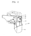
- FIG. 2 is a perspective view illustrating an apparatus for collecting an empty cartridge according to one embodiment of the present invention
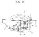
- FIG. 3 is a perspective view illustrating an unfolded state of a collecting unit of the apparatus for collecting an empty cartridge of FIG. 2 .
- the apparatus for collecting an empty cartridge 100 comprises a bracket 110, an operation pin 120, an upper link 130, a lower link 140 and a collecting unit 150.
- the bracket 110 is configured to support the apparatus for collecting an empty cartridge 100, and each component such as the upper link 130 and the lower link 140 is coupled to the bracket 110.
- the bracket 110 may be disposed to be adjacent to both side surfaces of the breech ring 40.
- One end of the bracket 110 may be fixed to the cannon holder 50, and may be configured such that the breech ring 40 performs a relative motion with respect to the apparatus 100 including the bracket 110 when the cannon barrel 20 moves backward and forward according to a firing state.
- the operation pin 120 may be formed to extend to one direction, and may be mounted to both side surfaces of the breech ring 40.
- the operation pin 120 fixed to the breech ring 40 may slide on one surface of the bracket 110 as the cannon barrel 20 moves backward and forward.
- At the bracket 110 may be formed a through hole extending to one direction in correspondence to a sliding path of the operation pin 120.
- the operation pin 120 may slide by penetrating the through hole.
- the upper link 130 is rotatably mounted to one surface of the bracket 110.
- the upper link 130 may be mounted to one surface or another surface of the bracket 110 facing the breech ring 40.
- the operation pin 120 slides with contacting the upper link 130.
- the upper link 130 includes a guide unit (first and second guide surfaces 131 and 132) to which the operation pin 120 sliding-contacts when the cannon barrel 20 moves backward and forward (refer to FIG. 4 ).
- the lower link 140 is concentric with the upper link 130, and is rotatably mounted to one surface of the bracket 110 facing the breech ring 40.
- At the lower link 140 may be formed a second locking protrusion 143 locked by a first locking protrusion 133 of the upper link 130 such that the lower link 140 rotates together with the upper link 130 by being engaged with the upper link 130 at a specific angle (refer to FIG. 4 ).
- the lower link 140 is formed to extend to one direction, and the two lower links 140 are connected to each other by a connecting plate 151.
- One end of a collecting cover 152 may be connected to the connecting plate 151.
- the collecting unit 150 is configured to be unfolded such that an empty cartridge extracted through the breech block 30 is collected at a specific point after a bump.
- the collecting unit 150 includes the collecting cover 152 which is in a folded state before firing but an unfolded state after firing.
- One end of the collecting cover 152 may be connected to the connecting plate 151, and another end thereof may be respectively connected to two brackets 110, or may be connected to a link 153 connected to the bracket 110.
- FIG. 4 is a disassembled view of the apparatus for collecting an empty cartridge 100 of FIG. 2 .
- the operation pin 120 is coupled to the breech ring 40 (not shown).
- sequentially coupled may be a shaft 160, a lower link 140, a first gap maintaining plate 165, an upper link return spring 166, a second gap maintaining plate 167, a lower link return spring 168, a third gap maintaining plate 169 and a coupling pin 161.
- the two lower links 140 may be connected to each other by the connecting plate 151, and one end of the colleting cover 152 may be connected to the connecting plate 151.
- the shaft 160 connects the upper link 130, the lower link 140, etc. to one another by penetrating through the bracket 110, and is finally coupled to the coupling pin 161.
- the upper link 130 and the lower link 140 rotate centering around the shaft 160.
- the upper link 130 includes a guide unit.
- the guide unit consists of a first guide surface 131 to which the operation pin 120 sliding-contacts when the cannon barrel 20 moves backward, and a second guide surface 132 adjacent to the first guide surface 131 and to which the operation pin 120 sliding-contacts when the cannon barrel 20 forward moves.
- the upper link 130 may be provided with a first locking protrusion 133.
- the first locking protrusion 133 may be protruding from the upper link 130 toward the lower link 140.
- the first locking protrusion 133 is formed to be locked by a second locking protrusion 143 of the lower link 140 at a specific angle.
- a stopper 141 configured to restrict separation of the operation pin 120 may be protruding from one surface of the lower link 140.
- the stopper 141 is configured to prevent separation of the operation pin 120 in a case that a rotation speed of the lower link 140 is faster than a sliding speed of the operation pin 120 when the cannon barrel 20 moves forward.
- the upper link return spring 166 provides an elastic force such that the upper link 130 returns to the initial position before firing once the operation pin 120 has completely passed the first or second guide surface 132.
- the upper link return spring 166 may be connected to the upper link 130 and the lower link 140, respectively.
- the lower link return spring 168 provides an elastic force such that the lower link 140 returns to the initial position before firing once the operation pin 120 has completely passed the second guide surface 132.
- the lower link return spring 168 may be connected to the lower link 140 and the bracket 110, respectively.
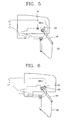
- FIGS. 5 to 8 are views illustrating operation states of the apparatus for collecting an empty cartridge 100 of FIG. 2 .
- FIG. 5 illustrates that the cannon barrel 20 is in a stationary state.
- FIG. 6 illustrates a state that ammunition is fired by a firing command, and the cannon barrel 20 moves backward.
- FIG. 7 illustrates a state that the cannon barrel 20 forward moves after backward moving.
- FIG. 8 illustrates that an unfolded state of the collecting unit 150 is maintained until an empty cartridge is completely collected.
- the collecting unit 150 of the apparatus for collecting an empty cartridge 100 is in a folded state (released state) before firing. Since the breech block 30 is open, ammunition can be loaded through the breech block 30.
- the operation pin 120 may be disposed so as to be spacing from the upper link 130 and the lower link 140.
- the guide unit (first and second guide surfaces 131 and 132) of the upper link 130 may be formed so as to be inclined along a sliding direction of the operation pin 120 when the cannon barrel 20 backward moves.
- the lower link 140 may be disposed toward the ground so as to prevent blocking of the breech block 30 occurring when the collecting unit 150 connected to the lower link 140 is unfolded.
- the breech block 30 is closed after ammunition is loaded in the cannon, and the cannon barrel 20 backward moves as the ammunition is consecutively fired.
- the operation pin 120 slides toward the upper link 130 along the first guide surface 131 of the upper link 130, thereby rotating the upper link 130.
- the upper link 130 returns to the initial position corresponding to the released state by the upper link return spring 166.
- the operation pin 120 slides along the second guide surface 132 of the upper link 130, thereby rotating the upper link 130.
- the second locking protrusion 143 is locked by the first locking protrusion 133.
- the lower link 140 rotates together with the upper link 130.
- the connecting plate 151 connected to the lower link 140 upwardly moves, and the collecting unit 150 is in an unfolded state, an empty cartridge collecting state. In this state, the breech block 30 is open, and an extracted empty cartridge is collected at a specific position after colliding with the collecting unit 150.
- the collecting unit 150 has to maintain an unfolded state until an empty cartridge is completely collected.
- the second guide surface 132 may have a sliding section (A) of a predetermined length such that the operation pin 120 is slidable until an empty cartridge is completely collected. While the operation pin 120 passes through the sliding section (A), an empty cartridge collecting state may be maintained.
- the operation pin 120 is separated from the guide unit (first and second guide surfaces 131 and 132) of the upper link 130, and the upper and lower links 130 and 140 return to the initial position corresponding to the released state by the upper and lower link return springs 166 and 168. Since the collecting unit 150 downward moves toward the ground, the breech block 30 is exposed to the outside, and the cannon is in a loadable state.
- the lower link rotates together with the upper link by being engaged with the upper link. And, the collecting unit is unfolded such that an empty cartridge is collected after colliding with the collecting unit. This may allow an empty cartridge to be automatically collected at a specific position.
- an empty cartridge may be automatically collected without a user's manipulations or an additional driving source since backward and forward movements of the cannon barrel are implemented.
Landscapes
- Engineering & Computer Science (AREA)
- General Engineering & Computer Science (AREA)
- Portable Nailing Machines And Staplers (AREA)
Claims (10)
- Vorrichtung (100) zum Auffangen einer leeren Patrone, die Vorrichtung dadurch gekennzeichnet, dass sie umfasst:einen Bügel (110), der angeordnet ist, von einer oder mehr Flächen eines Verschlussrings (40) zur Aufnahme eines Geschützrohrs (20) beabstandet zu sein;einen Betriebsstift (120), der an dem Verschlussring (40) benachbart zu dem Bügel (110) angebracht ist;ein oberes Verbindungsstück (130), das drehbar an einer Fläche des Bügels (110) angebracht ist und eingerichtet ist, gleitend mit dem Betriebsstift (120) in Kontakt zu sein;ein unteres Verbindungsstück (140), das mit dem oberen Verbindungsstück (130) konzentrisch ist, drehbar an einer Fläche des Bügels (110) angebracht ist, und sich zusammen mit dem oberen Verbindungsstück (130) dreht, indem es bei einem bestimmten Winkel mit dem oberen Verbindungsstück (130) in Eingriff steht; undeine Auffangeinheit (150) mit einem Ende, das mit dem unteren Verbindungsstück (140) verbunden ist, und einem anderen Ende, das mit dem Bügel (110) oder einem mit dem Bügel (110) verbundenen Verbindungsstück (153) verbunden ist, und das eingerichtet ist, derart ausgeklappt zu werden, dass eine leere Patrone, die aus dem Geschützrohr (20) extrahiert wurde, nach einem Aufprall auf die Auffangeinheit (150) aufgefangen wird,wobei, wenn sich das Geschützrohr (20) nach vorne bewegt, sich das untere Verbindungsstück (140) dreht, indem es mit dem oberen Verbindungsstück (130) in Eingriff steht, während der Betriebsstift (120) an dem oberen Verbindungsstück (130) gleitet, und die Auffangeinheit derart ausgeklappt wird, dass die leere Patrone nach dem Aufprall auf die Auffangeinheit (150) aufgefangen wird.
- Vorrichtung (100) nach Anspruch 1, wobei der Betriebsstift (120) an einer Fläche des Bügels (110) gleitet, während sich das Geschützrohr (20) vor und zurück bewegt.
- Vorrichtung (100) nach einem der Ansprüche 1 und 2, wobei ein erster Arretiervorsprung (133) von dem oberen Verbindungsstück (130) vorspringt, und ein zweiter Arretiervorsprung (143), der durch den ersten Arretiervorsprung (133) gesperrt wird, derart an dem unteren Verbindungsstück (140) gebildet ist, dass sich das untere Verbindungsstück (140) zusammen mit dem oberen Verbindungsstück (130) dreht, indem es bei einem bestimmten Winkel mit dem oberen Verbindungsstück (130) in Eingriff steht.
- Vorrichtung (100) nach einem der Ansprüche 1 bis 3, wobei das obere Verbindungsstück (130) eine Führungseinheit (131, 132) umfasst, mit der der Betriebsstift (120) gleitend in Kontakt ist, wenn sich das Geschützrohr (20) vor und zurück bewegt.
- Vorrichtung (100) nach Anspruch 4, wobei die Führungseinheit (131, 132) umfasst:eine erste Führungsfläche (131), mit der der Betriebsstift (120) gleitend in Kontakt ist, wenn sich das Geschützrohr (20) nach hinten bewegt; undeine zweite Führungsfläche (132) benachbart zu der ersten Führungsfläche (131), mit der der Betriebsstift gleitend in Kontakt ist, wenn sich das Geschützrohr (20) nach vorne bewegt.
- Vorrichtung (100) nach Anspruch 5, ferner umfassend eine oberes Verbindungsstück-Rückholfeder (166), die eingerichtet ist, eine elastische Kraft derart bereitzustellen, dass das obere Verbindungsstück (130) in eine bestimmte Position zurückkehrt, nachdem der Betriebsstift (120) die erste (131) oder die zweite Führungsfläche (132) vollständig passiert hat.
- Vorrichtung (100) nach Anspruch 5, ferner umfassend eine unteres Verbindungsstück-Rückholfeder (168), die eingerichtet ist, eine elastische Kraft derart bereitzustellen, dass das untere Verbindungsstück (140) in eine bestimmte Position zurückkehrt, nachdem der Betriebsstift (120) die zweite Führungsfläche (132)vollständig passiert hat.
- Vorrichtung (100) nach Anspruch 5, wobei die zweite Führungsfläche (132) einen Gleitabschnitt (A) mit einer derart vorherbestimmten Länge aufweist, dass der Betriebsstift (120) verschiebbar ist, bis eine leere Patrone vollständig aufgefangen ist.
- Vorrichtung (100) nach einem der Ansprüche 1 bis 8, wobei ein Anschlag (141), der eingerichtet ist, ein Ablösen des Betriebsstifts (120) zu verhindern, von einer Fläche des unteren Verbindungsstücks (140) benachbart zu dem oberen Verbindungsstück (130) vorspringt.
- Geschütz (10), umfassend:ein Geschützrohr (20), das eingerichtet ist, Munition abzuschießen;einen Verschlussblock (30), der eingerichtet ist, eine Patronenkammer des Geschützrohrs (20) zum Laden mit der Munition zu öffnen und zu schließen;einen Verschlussring (40), der eingerichtet ist, den Verschlussblock aufzunehmen;einen Geschützhalter (50), der eingerichtet ist, um das Geschützrohr (20) daran anzubringen, und in Bezug auf eine Bodenfläche so geneigt ist, dass das Verschlussrohr in eine bestimmte Abschussrichtung gerichtet ist; undeine Vorrichtung (100) zum Auffangen einer leeren Patrone nach einem der Ansprüche 1 bis 9.
Priority Applications (1)
| Application Number | Priority Date | Filing Date | Title |
|---|---|---|---|
| EP20110195779 EP2610573B1 (de) | 2011-12-27 | 2011-12-27 | Vorrichtung zum Sammeln von leeren Patronen und Geschütz damit |
Applications Claiming Priority (1)
| Application Number | Priority Date | Filing Date | Title |
|---|---|---|---|
| EP20110195779 EP2610573B1 (de) | 2011-12-27 | 2011-12-27 | Vorrichtung zum Sammeln von leeren Patronen und Geschütz damit |
Publications (2)
| Publication Number | Publication Date |
|---|---|
| EP2610573A1 EP2610573A1 (de) | 2013-07-03 |
| EP2610573B1 true EP2610573B1 (de) | 2014-07-23 |
Family
ID=45421985
Family Applications (1)
| Application Number | Title | Priority Date | Filing Date |
|---|---|---|---|
| EP20110195779 Active EP2610573B1 (de) | 2011-12-27 | 2011-12-27 | Vorrichtung zum Sammeln von leeren Patronen und Geschütz damit |
Country Status (1)
| Country | Link |
|---|---|
| EP (1) | EP2610573B1 (de) |
Cited By (1)
| Publication number | Priority date | Publication date | Assignee | Title |
|---|---|---|---|---|
| RU2827783C1 (ru) * | 2023-10-12 | 2024-10-02 | Акционерное общество "Конструкторское бюро приборостроения им. академика А.Г. Шипунова" | Гранатометная установка |
Families Citing this family (1)
| Publication number | Priority date | Publication date | Assignee | Title |
|---|---|---|---|---|
| CN104964596B (zh) * | 2015-07-21 | 2016-07-06 | 海门市中德电子发展有限公司 | 一种大比例模型坦克自动填弹火炮装置 |
Family Cites Families (4)
| Publication number | Priority date | Publication date | Assignee | Title |
|---|---|---|---|---|
| BE532196A (de) * | 1953-10-01 | |||
| US3238844A (en) * | 1963-11-21 | 1966-03-08 | Bofors Ab | Guiding device for guiding shell casings ejected by the recoil of a gun |
| US5651208A (en) * | 1995-08-03 | 1997-07-29 | Benson; Phillip Dean | Cartridge casting collector |
| WO2008140514A1 (en) * | 2007-05-08 | 2008-11-20 | Moody Joseph R | Machine gun ammunition holder with ejection deflector |
-
2011
- 2011-12-27 EP EP20110195779 patent/EP2610573B1/de active Active
Cited By (1)
| Publication number | Priority date | Publication date | Assignee | Title |
|---|---|---|---|---|
| RU2827783C1 (ru) * | 2023-10-12 | 2024-10-02 | Акционерное общество "Конструкторское бюро приборостроения им. академика А.Г. Шипунова" | Гранатометная установка |
Also Published As
| Publication number | Publication date |
|---|---|
| EP2610573A1 (de) | 2013-07-03 |
Similar Documents
| Publication | Publication Date | Title |
|---|---|---|
| US10180298B2 (en) | Bolt hold open mechanism system and method of using it | |
| US8555767B2 (en) | Apparatus for collecting an empty cartridge and cannon having the same | |
| US9347726B1 (en) | Striker style firearm with improved mechanical function | |
| US20210270555A1 (en) | Bolt Hold Open Mechanism System and Method of Using It | |
| CN109661258B (zh) | 供弹机构及发射装置 | |
| CN109690228B (zh) | 用于从连接至主武器和/或副武器的弹药链或条弹出弹壳和/或连接器的弹出装置 | |
| US9777976B2 (en) | Spent cartridges router | |
| KR101763240B1 (ko) | 탄환의 장착이 용이한 최루탄 발사기 | |
| KR101761243B1 (ko) | 탄창 자동회전 리볼버형 최루탄 발사기 | |
| CA2910962C (en) | Minigun with improved access door | |
| EP2610573A1 (de) | Vorrichtung zum Sammeln von leeren Patronen und Geschütz damit | |
| CN103206895B (zh) | 组合弹膛式转膛枪 | |
| KR102142667B1 (ko) | 탄창의 호환이 가능한 자동회전 리볼버형 최루탄 발사기 | |
| JP2021513049A (ja) | 小火器の安全装置 | |
| KR20130006040A (ko) | 화포의 안전장전장치 | |
| US3802313A (en) | Machine gun having dual feeding means for selectively feeding cartridges | |
| US20170082386A1 (en) | Rifle loading device | |
| EP2610572B1 (de) | Vorrichtung zum Öffnen und Schließen eines Verschlussblockes und Geschütz damit | |
| RU2662307C1 (ru) | Устройство для отвода звеньев автоматического оружия | |
| RU2390713C2 (ru) | Пулемет | |
| RU2861660C1 (ru) | Тракт питания для автоматического гранатомета | |
| RU2632555C2 (ru) | Узел оружия, содержащий лоток для выброса патронных гильз | |
| KR101222461B1 (ko) | 탄피회수장치 및 이를 구비하는 화포 | |
| RU2623850C1 (ru) | Автоматическое оружие | |
| RU2381433C2 (ru) | Патронный выбрасыватель |
Legal Events
| Date | Code | Title | Description |
|---|---|---|---|
| PUAI | Public reference made under article 153(3) epc to a published international application that has entered the european phase |
Free format text: ORIGINAL CODE: 0009012 |
|
| 17P | Request for examination filed |
Effective date: 20111227 |
|
| AK | Designated contracting states |
Kind code of ref document: A1 Designated state(s): AL AT BE BG CH CY CZ DE DK EE ES FI FR GB GR HR HU IE IS IT LI LT LU LV MC MK MT NL NO PL PT RO RS SE SI SK SM TR |
|
| AX | Request for extension of the european patent |
Extension state: BA ME |
|
| GRAP | Despatch of communication of intention to grant a patent |
Free format text: ORIGINAL CODE: EPIDOSNIGR1 |
|
| RIC1 | Information provided on ipc code assigned before grant |
Ipc: F41A 9/60 20060101AFI20140128BHEP |
|
| INTG | Intention to grant announced |
Effective date: 20140211 |
|
| GRAS | Grant fee paid |
Free format text: ORIGINAL CODE: EPIDOSNIGR3 |
|
| GRAA | (expected) grant |
Free format text: ORIGINAL CODE: 0009210 |
|
| AK | Designated contracting states |
Kind code of ref document: B1 Designated state(s): AL AT BE BG CH CY CZ DE DK EE ES FI FR GB GR HR HU IE IS IT LI LT LU LV MC MK MT NL NO PL PT RO RS SE SI SK SM TR |
|
| REG | Reference to a national code |
Ref country code: GB Ref legal event code: FG4D |
|
| REG | Reference to a national code |
Ref country code: CH Ref legal event code: EP |
|
| REG | Reference to a national code |
Ref country code: IE Ref legal event code: FG4D |
|
| REG | Reference to a national code |
Ref country code: AT Ref legal event code: REF Ref document number: 679111 Country of ref document: AT Kind code of ref document: T Effective date: 20140815 |
|
| REG | Reference to a national code |
Ref country code: DE Ref legal event code: R096 Ref document number: 602011008550 Country of ref document: DE Effective date: 20140904 |
|
| REG | Reference to a national code |
Ref country code: AT Ref legal event code: MK05 Ref document number: 679111 Country of ref document: AT Kind code of ref document: T Effective date: 20140723 |
|
| REG | Reference to a national code |
Ref country code: NL Ref legal event code: VDEP Effective date: 20140723 |
|
| REG | Reference to a national code |
Ref country code: LT Ref legal event code: MG4D |
|
| PG25 | Lapsed in a contracting state [announced via postgrant information from national office to epo] |
Ref country code: ES Free format text: LAPSE BECAUSE OF FAILURE TO SUBMIT A TRANSLATION OF THE DESCRIPTION OR TO PAY THE FEE WITHIN THE PRESCRIBED TIME-LIMIT Effective date: 20140723 Ref country code: NO Free format text: LAPSE BECAUSE OF FAILURE TO SUBMIT A TRANSLATION OF THE DESCRIPTION OR TO PAY THE FEE WITHIN THE PRESCRIBED TIME-LIMIT Effective date: 20141023 Ref country code: SE Free format text: LAPSE BECAUSE OF FAILURE TO SUBMIT A TRANSLATION OF THE DESCRIPTION OR TO PAY THE FEE WITHIN THE PRESCRIBED TIME-LIMIT Effective date: 20140723 Ref country code: GR Free format text: LAPSE BECAUSE OF FAILURE TO SUBMIT A TRANSLATION OF THE DESCRIPTION OR TO PAY THE FEE WITHIN THE PRESCRIBED TIME-LIMIT Effective date: 20141024 Ref country code: LT Free format text: LAPSE BECAUSE OF FAILURE TO SUBMIT A TRANSLATION OF THE DESCRIPTION OR TO PAY THE FEE WITHIN THE PRESCRIBED TIME-LIMIT Effective date: 20140723 Ref country code: PT Free format text: LAPSE BECAUSE OF FAILURE TO SUBMIT A TRANSLATION OF THE DESCRIPTION OR TO PAY THE FEE WITHIN THE PRESCRIBED TIME-LIMIT Effective date: 20141124 Ref country code: FI Free format text: LAPSE BECAUSE OF FAILURE TO SUBMIT A TRANSLATION OF THE DESCRIPTION OR TO PAY THE FEE WITHIN THE PRESCRIBED TIME-LIMIT Effective date: 20140723 Ref country code: BG Free format text: LAPSE BECAUSE OF FAILURE TO SUBMIT A TRANSLATION OF THE DESCRIPTION OR TO PAY THE FEE WITHIN THE PRESCRIBED TIME-LIMIT Effective date: 20141023 |
|
| PG25 | Lapsed in a contracting state [announced via postgrant information from national office to epo] |
Ref country code: LV Free format text: LAPSE BECAUSE OF FAILURE TO SUBMIT A TRANSLATION OF THE DESCRIPTION OR TO PAY THE FEE WITHIN THE PRESCRIBED TIME-LIMIT Effective date: 20140723 Ref country code: HR Free format text: LAPSE BECAUSE OF FAILURE TO SUBMIT A TRANSLATION OF THE DESCRIPTION OR TO PAY THE FEE WITHIN THE PRESCRIBED TIME-LIMIT Effective date: 20140723 Ref country code: AT Free format text: LAPSE BECAUSE OF FAILURE TO SUBMIT A TRANSLATION OF THE DESCRIPTION OR TO PAY THE FEE WITHIN THE PRESCRIBED TIME-LIMIT Effective date: 20140723 Ref country code: IS Free format text: LAPSE BECAUSE OF FAILURE TO SUBMIT A TRANSLATION OF THE DESCRIPTION OR TO PAY THE FEE WITHIN THE PRESCRIBED TIME-LIMIT Effective date: 20141123 Ref country code: NL Free format text: LAPSE BECAUSE OF FAILURE TO SUBMIT A TRANSLATION OF THE DESCRIPTION OR TO PAY THE FEE WITHIN THE PRESCRIBED TIME-LIMIT Effective date: 20140723 Ref country code: RS Free format text: LAPSE BECAUSE OF FAILURE TO SUBMIT A TRANSLATION OF THE DESCRIPTION OR TO PAY THE FEE WITHIN THE PRESCRIBED TIME-LIMIT Effective date: 20140723 Ref country code: PL Free format text: LAPSE BECAUSE OF FAILURE TO SUBMIT A TRANSLATION OF THE DESCRIPTION OR TO PAY THE FEE WITHIN THE PRESCRIBED TIME-LIMIT Effective date: 20140723 Ref country code: CY Free format text: LAPSE BECAUSE OF FAILURE TO SUBMIT A TRANSLATION OF THE DESCRIPTION OR TO PAY THE FEE WITHIN THE PRESCRIBED TIME-LIMIT Effective date: 20140723 |
|
| REG | Reference to a national code |
Ref country code: DE Ref legal event code: R097 Ref document number: 602011008550 Country of ref document: DE |
|
| PG25 | Lapsed in a contracting state [announced via postgrant information from national office to epo] |
Ref country code: SK Free format text: LAPSE BECAUSE OF FAILURE TO SUBMIT A TRANSLATION OF THE DESCRIPTION OR TO PAY THE FEE WITHIN THE PRESCRIBED TIME-LIMIT Effective date: 20140723 Ref country code: CZ Free format text: LAPSE BECAUSE OF FAILURE TO SUBMIT A TRANSLATION OF THE DESCRIPTION OR TO PAY THE FEE WITHIN THE PRESCRIBED TIME-LIMIT Effective date: 20140723 Ref country code: EE Free format text: LAPSE BECAUSE OF FAILURE TO SUBMIT A TRANSLATION OF THE DESCRIPTION OR TO PAY THE FEE WITHIN THE PRESCRIBED TIME-LIMIT Effective date: 20140723 Ref country code: RO Free format text: LAPSE BECAUSE OF FAILURE TO SUBMIT A TRANSLATION OF THE DESCRIPTION OR TO PAY THE FEE WITHIN THE PRESCRIBED TIME-LIMIT Effective date: 20140723 Ref country code: DK Free format text: LAPSE BECAUSE OF FAILURE TO SUBMIT A TRANSLATION OF THE DESCRIPTION OR TO PAY THE FEE WITHIN THE PRESCRIBED TIME-LIMIT Effective date: 20140723 |
|
| PLBE | No opposition filed within time limit |
Free format text: ORIGINAL CODE: 0009261 |
|
| STAA | Information on the status of an ep patent application or granted ep patent |
Free format text: STATUS: NO OPPOSITION FILED WITHIN TIME LIMIT |
|
| PG25 | Lapsed in a contracting state [announced via postgrant information from national office to epo] |
Ref country code: BE Free format text: LAPSE BECAUSE OF NON-PAYMENT OF DUE FEES Effective date: 20141231 |
|
| 26N | No opposition filed |
Effective date: 20150424 |
|
| PG25 | Lapsed in a contracting state [announced via postgrant information from national office to epo] |
Ref country code: LU Free format text: LAPSE BECAUSE OF FAILURE TO SUBMIT A TRANSLATION OF THE DESCRIPTION OR TO PAY THE FEE WITHIN THE PRESCRIBED TIME-LIMIT Effective date: 20141227 |
|
| REG | Reference to a national code |
Ref country code: CH Ref legal event code: PL |
|
| REG | Reference to a national code |
Ref country code: IE Ref legal event code: MM4A |
|
| PG25 | Lapsed in a contracting state [announced via postgrant information from national office to epo] |
Ref country code: CH Free format text: LAPSE BECAUSE OF NON-PAYMENT OF DUE FEES Effective date: 20141231 Ref country code: IE Free format text: LAPSE BECAUSE OF NON-PAYMENT OF DUE FEES Effective date: 20141227 Ref country code: LI Free format text: LAPSE BECAUSE OF NON-PAYMENT OF DUE FEES Effective date: 20141231 |
|
| PG25 | Lapsed in a contracting state [announced via postgrant information from national office to epo] |
Ref country code: SI Free format text: LAPSE BECAUSE OF FAILURE TO SUBMIT A TRANSLATION OF THE DESCRIPTION OR TO PAY THE FEE WITHIN THE PRESCRIBED TIME-LIMIT Effective date: 20140723 |
|
| REG | Reference to a national code |
Ref country code: FR Ref legal event code: PLFP Year of fee payment: 5 |
|
| PG25 | Lapsed in a contracting state [announced via postgrant information from national office to epo] |
Ref country code: SM Free format text: LAPSE BECAUSE OF FAILURE TO SUBMIT A TRANSLATION OF THE DESCRIPTION OR TO PAY THE FEE WITHIN THE PRESCRIBED TIME-LIMIT Effective date: 20140723 |
|
| PG25 | Lapsed in a contracting state [announced via postgrant information from national office to epo] |
Ref country code: MC Free format text: LAPSE BECAUSE OF FAILURE TO SUBMIT A TRANSLATION OF THE DESCRIPTION OR TO PAY THE FEE WITHIN THE PRESCRIBED TIME-LIMIT Effective date: 20140723 |
|
| PG25 | Lapsed in a contracting state [announced via postgrant information from national office to epo] |
Ref country code: MT Free format text: LAPSE BECAUSE OF FAILURE TO SUBMIT A TRANSLATION OF THE DESCRIPTION OR TO PAY THE FEE WITHIN THE PRESCRIBED TIME-LIMIT Effective date: 20140723 Ref country code: HU Free format text: LAPSE BECAUSE OF FAILURE TO SUBMIT A TRANSLATION OF THE DESCRIPTION OR TO PAY THE FEE WITHIN THE PRESCRIBED TIME-LIMIT; INVALID AB INITIO Effective date: 20111227 Ref country code: BE Free format text: LAPSE BECAUSE OF FAILURE TO SUBMIT A TRANSLATION OF THE DESCRIPTION OR TO PAY THE FEE WITHIN THE PRESCRIBED TIME-LIMIT Effective date: 20140723 Ref country code: TR Free format text: LAPSE BECAUSE OF FAILURE TO SUBMIT A TRANSLATION OF THE DESCRIPTION OR TO PAY THE FEE WITHIN THE PRESCRIBED TIME-LIMIT Effective date: 20140723 |
|
| REG | Reference to a national code |
Ref country code: FR Ref legal event code: PLFP Year of fee payment: 6 |
|
| REG | Reference to a national code |
Ref country code: FR Ref legal event code: PLFP Year of fee payment: 7 |
|
| PG25 | Lapsed in a contracting state [announced via postgrant information from national office to epo] |
Ref country code: MK Free format text: LAPSE BECAUSE OF FAILURE TO SUBMIT A TRANSLATION OF THE DESCRIPTION OR TO PAY THE FEE WITHIN THE PRESCRIBED TIME-LIMIT Effective date: 20140723 |
|
| PG25 | Lapsed in a contracting state [announced via postgrant information from national office to epo] |
Ref country code: AL Free format text: LAPSE BECAUSE OF FAILURE TO SUBMIT A TRANSLATION OF THE DESCRIPTION OR TO PAY THE FEE WITHIN THE PRESCRIBED TIME-LIMIT Effective date: 20140723 |
|
| REG | Reference to a national code |
Ref country code: DE Ref legal event code: R082 Ref document number: 602011008550 Country of ref document: DE Representative=s name: KILBURN & STRODE LLP, NL |
|
| PGFP | Annual fee paid to national office [announced via postgrant information from national office to epo] |
Ref country code: DE Payment date: 20250930 Year of fee payment: 15 |
|
| PGFP | Annual fee paid to national office [announced via postgrant information from national office to epo] |
Ref country code: GB Payment date: 20251001 Year of fee payment: 15 |
|
| PGFP | Annual fee paid to national office [announced via postgrant information from national office to epo] |
Ref country code: IT Payment date: 20251121 Year of fee payment: 15 |
|
| PGFP | Annual fee paid to national office [announced via postgrant information from national office to epo] |
Ref country code: FR Payment date: 20251110 Year of fee payment: 15 |