EP2610599A2 - Temperaturmessvorrichtung und Verfahren zum Aufbau davon - Google Patents
Temperaturmessvorrichtung und Verfahren zum Aufbau davon Download PDFInfo
- Publication number
- EP2610599A2 EP2610599A2 EP12197523.9A EP12197523A EP2610599A2 EP 2610599 A2 EP2610599 A2 EP 2610599A2 EP 12197523 A EP12197523 A EP 12197523A EP 2610599 A2 EP2610599 A2 EP 2610599A2
- Authority
- EP
- European Patent Office
- Prior art keywords
- housing
- temperature sensor
- sensing device
- cooling
- cooling air
- Prior art date
- Legal status (The legal status is an assumption and is not a legal conclusion. Google has not performed a legal analysis and makes no representation as to the accuracy of the status listed.)
- Granted
Links
- 238000000034 method Methods 0.000 title claims abstract description 31
- 238000001816 cooling Methods 0.000 claims abstract description 142
- 238000002485 combustion reaction Methods 0.000 claims description 43
- 230000008878 coupling Effects 0.000 claims description 4
- 238000010168 coupling process Methods 0.000 claims description 4
- 238000005859 coupling reaction Methods 0.000 claims description 4
- 239000007789 gas Substances 0.000 description 58
- 239000000567 combustion gas Substances 0.000 description 22
- 239000000446 fuel Substances 0.000 description 12
- BASFCYQUMIYNBI-UHFFFAOYSA-N platinum Chemical compound [Pt] BASFCYQUMIYNBI-UHFFFAOYSA-N 0.000 description 12
- 239000000463 material Substances 0.000 description 7
- 229910052697 platinum Inorganic materials 0.000 description 6
- 239000000956 alloy Substances 0.000 description 4
- 229910045601 alloy Inorganic materials 0.000 description 3
- 238000004891 communication Methods 0.000 description 3
- 229910018487 Ni—Cr Inorganic materials 0.000 description 2
- 238000009529 body temperature measurement Methods 0.000 description 2
- VNNRSPGTAMTISX-UHFFFAOYSA-N chromium nickel Chemical compound [Cr].[Ni] VNNRSPGTAMTISX-UHFFFAOYSA-N 0.000 description 2
- 238000005259 measurement Methods 0.000 description 2
- 230000003647 oxidation Effects 0.000 description 2
- 238000007254 oxidation reaction Methods 0.000 description 2
- 230000008646 thermal stress Effects 0.000 description 2
- 238000011144 upstream manufacturing Methods 0.000 description 2
- 230000006978 adaptation Effects 0.000 description 1
- 230000003466 anti-cipated effect Effects 0.000 description 1
- 239000000919 ceramic Substances 0.000 description 1
- 230000003247 decreasing effect Effects 0.000 description 1
- 238000009413 insulation Methods 0.000 description 1
- 239000012774 insulation material Substances 0.000 description 1
- 238000012986 modification Methods 0.000 description 1
- 230000004048 modification Effects 0.000 description 1
- 238000005457 optimization Methods 0.000 description 1
- 239000000843 powder Substances 0.000 description 1
- 229910052703 rhodium Inorganic materials 0.000 description 1
- 239000010948 rhodium Substances 0.000 description 1
- MHOVAHRLVXNVSD-UHFFFAOYSA-N rhodium atom Chemical compound [Rh] MHOVAHRLVXNVSD-UHFFFAOYSA-N 0.000 description 1
- 238000012546 transfer Methods 0.000 description 1
- 238000009827 uniform distribution Methods 0.000 description 1
- 238000013022 venting Methods 0.000 description 1
Images



Classifications
-
- G—PHYSICS
- G01—MEASURING; TESTING
- G01K—MEASURING TEMPERATURE; MEASURING QUANTITY OF HEAT; THERMALLY-SENSITIVE ELEMENTS NOT OTHERWISE PROVIDED FOR
- G01K1/00—Details of thermometers not specially adapted for particular types of thermometer
- G01K1/08—Protective devices, e.g. casings
- G01K1/12—Protective devices, e.g. casings for preventing damage due to heat overloading
-
- G—PHYSICS
- G01—MEASURING; TESTING
- G01K—MEASURING TEMPERATURE; MEASURING QUANTITY OF HEAT; THERMALLY-SENSITIVE ELEMENTS NOT OTHERWISE PROVIDED FOR
- G01K1/00—Details of thermometers not specially adapted for particular types of thermometer
- G01K1/14—Supports; Fastening devices; Arrangements for mounting thermometers in particular locations
-
- G—PHYSICS
- G01—MEASURING; TESTING
- G01K—MEASURING TEMPERATURE; MEASURING QUANTITY OF HEAT; THERMALLY-SENSITIVE ELEMENTS NOT OTHERWISE PROVIDED FOR
- G01K13/00—Thermometers specially adapted for specific purposes
- G01K13/02—Thermometers specially adapted for specific purposes for measuring temperature of moving fluids or granular materials capable of flow
-
- G—PHYSICS
- G01—MEASURING; TESTING
- G01K—MEASURING TEMPERATURE; MEASURING QUANTITY OF HEAT; THERMALLY-SENSITIVE ELEMENTS NOT OTHERWISE PROVIDED FOR
- G01K13/00—Thermometers specially adapted for specific purposes
- G01K13/02—Thermometers specially adapted for specific purposes for measuring temperature of moving fluids or granular materials capable of flow
- G01K13/024—Thermometers specially adapted for specific purposes for measuring temperature of moving fluids or granular materials capable of flow of moving gases
-
- Y—GENERAL TAGGING OF NEW TECHNOLOGICAL DEVELOPMENTS; GENERAL TAGGING OF CROSS-SECTIONAL TECHNOLOGIES SPANNING OVER SEVERAL SECTIONS OF THE IPC; TECHNICAL SUBJECTS COVERED BY FORMER USPC CROSS-REFERENCE ART COLLECTIONS [XRACs] AND DIGESTS
- Y10—TECHNICAL SUBJECTS COVERED BY FORMER USPC
- Y10T—TECHNICAL SUBJECTS COVERED BY FORMER US CLASSIFICATION
- Y10T29/00—Metal working
- Y10T29/49—Method of mechanical manufacture
- Y10T29/49826—Assembling or joining
Definitions
- the field of this disclosure relates generally to sensors and, more particularly, to a temperature sensing device for a combustion section of a gas turbine engine.
- Exhaust gas temperature in the combustion section of a gas turbine engine is an operating parameter that is often used by the engine control unit to determine fuel input to the combustor.
- accurate measurements of the exhaust gas temperature within the combustor can facilitate improved operating efficiency of the engine by enabling optimized fuel inputs.
- engine components within, and downstream of, the combustion section e.g., turbine blades
- the useful life of these downstream components is often estimated using expected exhaust gas temperatures in the combustor. Therefore, accurate measurements of the exhaust gas temperature can facilitate making the expected exhaust gas temperatures more accurate and, as a result, facilitate making the component life estimations more accurate as well.
- At least some known exhaust gas temperature (EGT) sensors used in gas turbine engines include a thermocouple element.
- these thermocouple elements often have smaller diameters.
- exhaust gases within the engine can reach velocities of at least 240 m/s, and these smaller diameter thermocouple elements typically do not have enough rigidity to resist the drag associated with the exhaust gas flow velocity.
- some known EGT sensors have thermocouple elements that are disposed within a more rigid housing to provide increased support to withstand the associated drag, and most of these housings are fabricated from higher temperature rated alloys.
- the exhaust gases can reach temperatures of at least 2300°F.
- a method of assembling a temperature sensing device for a gas turbine engine includes providing a temperature sensor and providing a housing configured to envelop the temperature sensor. The method further includes mounting the temperature sensor within the housing such that a portion of the temperature sensor is disposed outside of the housing and such that the housing is configured to receive a flow of cooling air.
- a temperature sensing device for a gas turbine engine.
- the temperature sensing device includes a temperature sensor and a housing configured to envelop the temperature sensor such that a portion of the temperature sensor is disposed outside of the housing.
- the housing is configured to receive a flow of cooling air.
- a gas turbine engine in another aspect, includes a combustion chamber and a temperature sensing device extending into the combustion chamber.
- the temperature sensing device includes a temperature sensor and a housing configured to envelop the temperature sensor such that a portion of the temperature sensor is disposed outside of the housing.
- the housing is configured to receive a flow of cooling air.
- the following detailed description sets forth a temperature sensing device and a method of assembling the same by way of example and not by way of limitation.
- the description should clearly enable one of ordinary skill in the art to make and use the temperature sensing device, and the description sets forth several embodiments, adaptations, variations, alternatives, and uses of the temperature sensing device, including what is presently believed to be the best mode thereof.
- the temperature sensing device is described herein as being applied to a preferred embodiment, namely a gas turbine engine. However, it is contemplated that the temperature sensing device and the method of assembling the same have general application in a broad range of systems and a variety of other commercial, industrial, and consumer applications.
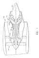
- Figure 1 is a schematic illustration of an exemplary gas turbine engine 100 including a fan section 102, a compressor section 104, a combustion section 106, a high pressure turbine section 108, and a low pressure turbine section 110 that are aligned along a centerline axis 107.
- air flows through fan section 102 and is supplied to compressor section 104.
- the compressed air is delivered to combustion section 106, in which it is mixed with fuel and ignited to produce combustion gases.
- the combustion gases flow from combustion section 106 through turbine sections 108, 110 and are subsequently exhausted from gas turbine engine 100.
- gas turbine engine 100 may include any suitable number of fan sections, compressor sections, and/or turbine sections arranged in any suitable manner.
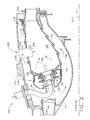
- FIG. 2 is a schematic illustration of combustion section 106.
- combustion section 106 includes an annular inner casing structure 114, an annular outer casing structure 116, and a combustor assembly 118.
- Combustor assembly 118 is disposed between inner casing structure 114 and outer casing structure 116, and combustor assembly 118 includes a fuel nozzle 120, an igniter (not shown), and a pair of inner and outer liners 122, 124.
- Fuel nozzle 120 extends through outer casing structure 116, and liners 122, 124 are coupled to fuel nozzle 120 and extend from fuel nozzle 120 to a nozzle 126 of high pressure turbine section 108 such that a combustion chamber 128 is defined between liners 122, 124.
- An inner bypass flow path 130 is defined between inner casing structure 114 and inner liner 122, and an outer bypass flow path 132 is defined between outer casing structure 116 and outer liner 124.
- Compressed air 134 delivered from compressor section 104 to combustion section 106 is divided into an inner bypass flow 136 that cools inner liner 122, an outer bypass flow 138 that cools outer liner 124, and an intermediate flow 140 that is directed into combustion chamber 128 to be mixed with fuel and ignited to produce a combustion gas flow 142 through combustion chamber 128 and into nozzle 126 of high pressure turbine section 108.
- a temperature sensing device 200 (e.g., an exhaust gas temperature (EGT) sensing device) is coupled to outer casing structure 116 and extends through outer bypass flow path 132 and into combustion chamber 128 through outer liner 124 to facilitate determining a temperature of combustion gas flow 142.
- temperature sensing device 200 may be coupled to inner casing structure 114 and extend into combustion chamber 128 through inner bypass flow path 130.
- temperature sensing device 200 may be coupled to any suitable structure of gas turbine engine 100 that facilitates enabling temperature sensing device 200 to function as described herein.
- references to temperature sensing device 200 in terms of orientation within gas turbine engine 100 are intended to mean that temperature sensing device 200 is configured to be oriented in such a manner when temperature sensing device 200 is mounted within gas turbine engine 100 as described herein, and such references to orientation are not intended to limit the scope of this disclosure to only those temperature sensing devices that are actually mounted within gas turbine engine 100. Rather, this disclosure is intended to apply to temperature sensing devices in general, whether mounted within a gas turbine engine or not.
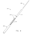
- FIGs 3 and 4 are perspective and exploded views, respectively, of temperature sensing device 200.
- temperature sensing device 200 includes a housing 202, a cooling system 204, and a sensor unit 206.
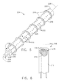
- Figure 5 is a perspective view of cooling system 204 with sensor unit 206 disposed therein
- Figure 6 is a schematic partial cross-sectional illustration of a portion of sensor unit 206
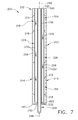
- Figure 7 is a cross-sectional view of temperature sensing device 200 with the assembled cooling system 204 and sensor unit 206 disposed within housing 202.
- sensor unit 206 has a longitudinal axis 214 and includes a temperature sensor 208 (e.g., a platinum-based, S-type thermocouple) disposed within an insulation material 210 (e.g., a ceramic powder) and housed within a shell 212, such as a grain-stabilized, platinum-based shell (i.e., sensor unit 206 includes a sealed and isolated temperature sensor 208).
- Temperature sensor 208 has a tip 215.
- shell 212 may include an array of longitudinally extending, circumferentially spaced-apart fins that facilitate locating sensor unit 206 in housing 202, as described in more detail below.
- shell 212 may be fabricated from an austenitic nickel-chromium-based alloy material.
- sensor unit 206 may have any suitable configuration of temperature sensor, insulation, and/or shell fabricated from any suitable material that facilitates enabling temperature sensing device 200 to function as described herein.
- cooling system 204 includes a cooling channel 216 and a plurality of support ribs 218 extending outward from cooling channel 216.
- Cooling channel 216 has a proximal end 220, a distal end 222, a forward region 224, an aft region 226, and a longitudinal axis 228 extending from proximal end 220 to distal end 222.
- Forward region 224 has a plurality of parallel, longitudinally extending rows 230 of spaced-apart impingement apertures 232, and distal end 222 has a generally annular arrangement 234 of impingement apertures 232 spaced apart from one another about a sensor unit through hole 236.
- support ribs 218 are generally ring-shaped and are coupled to (e.g., brazed to) cooling channel 216 in a longitudinally spaced-apart relationship.
- support ribs 218 may be integrally formed with cooling channel 216, rather than being formed separately from and coupled to cooling channel 216.
- support ribs 218 may have any suitable shape and arrangement on cooling channel 216 that facilitates enabling temperature sensing device 200 to function as described herein.
- cooling channel 216 is surrounded by cooling air within housing 202 during operation of gas turbine engine 100 such that cooling channel 216 is not exposed to combustion gas flow 142 within combustion chamber 128.
- cooling channel 216 is configured to have a cooler service temperature of about the anticipated temperature of the cooling air that surrounds cooling channel 216 within housing 202 during operation. In this manner, cooling channel 216 is less susceptible to creep and, therefore, is configured to provide significant structural support for temperature sensing device 200 to withstand the velocity of combustion gas flow 142 through combustion chamber 128 during operation of gas turbine engine 100.
- cooling channel 216 is fabricated from an austenitic nickel-chromium-based alloy for high strength, low conductivity, and low oxidation. Alternatively, cooling channel 216 may be fabricated from any suitable material that facilitates enabling temperature sensing device 200 to function as described herein.
- housing 202 is generally cylindrically shaped and has a proximal end 240, a distal end 242, a forward region 244, an aft region 246, and a longitudinal axis 248 extending from proximal end 240 to distal end 242.
- housing 202 is fabricated from a platinum-based material to facilitate better resistance against oxidation and thermal fatigue associated with exposure to combustion gas flow 142 within combustion chamber 128.
- housing 202 may be fabricated from a platinum-based material having rhodium.
- housing 202 may be fabricated from any suitable material that facilitates enabling temperature sensing device 200 to function as described herein.
- a sensor unit through hole 250 is defined in distal end 242, and a substantially longitudinal row 252 of spaced-apart exit apertures 254 is defined on aft region 246.
- exit apertures 254 may be generally circular in shape and may be substantially equally spaced.
- exit apertures 254 may be elongated in shape (e.g. elliptically shaped).
- exit apertures 254 may vary in shape and/or spacing along longitudinal axis 248 to facilitate increasing or decreasing cooling air flow out of housing 202 at predetermined locations along longitudinal axis 248 (e.g., exit apertures 254 may be smaller near proximal end 240 of housing 202 and larger near distal end 242 of housing 202).
- housing 202 may also include a tip cover (not shown) (e.g., fabricated from a platinum-based material such as, for example, a grain stabilized platinum material), and the tip cover extends from distal end 242 of housing 202 at sensor unit through hole 250.
- the tip cover may be pressed and/or welded to distal end 242 such that, when sensor unit 206 is disposed within housing 202, tip 215 is disposed within the tip cover of housing 202 (e.g., shell 212 may have fingers or threads to locate tip 215 within the tip cover).
- housing 202 may have any suitable configuration that facilitates enabling housing 202 to function as described herein (e.g., housing 202 may have a single, elongated exit slot extending substantially from proximal end 240 to distal end 242, rather than having spaced-apart exit apertures 254; or exit apertures 254 may not be defined on aft region 246 but, rather, may be defined on a side region of housing 202).
- housing 202 includes an internal support sleeve 238 that is integrally formed with distal end 242.
- Support sleeve 238 is aligned with sensor unit through hole 250 and extends longitudinally from distal end 242 to proximal end 240 such that support sleeve 238 is open at both ends 240, 242 of housing 202.
- sensor unit 206 is inserted into support sleeve 238 such that sensor unit 206 is substantially centrally located within housing 202 with a portion of sensor unit 206 (e.g., tip 215) disposed outside of housing 202 via sensor unit through hole 250.
- shell 212 of sensor unit 206 may be provided with the array of longitudinally extending fins described above, and the fins would facilitate locating sensor unit 206 within cooling channel 216 (e.g., substantially centrally within cooling channel 216) while still enabling cooling air to flow longitudinally along cooling channel 216.
- cooling system 204 and sensor unit 206 are disposed within housing 202 such that cooling channel 216 envelops support sleeve 238 (and, therefore, sensor unit 206) and such that housing 202 envelops cooling channel 216 with support ribs 218 locating cooling channel 216 substantially centrally within housing 202.
- adjacent support ribs 218 define a plurality of separate, annular cooling regions 256 arranged longitudinally along housing 202 to facilitate a more uniform distribution of cooling air throughout housing 202.
- support ribs 218 are not coupled to housing 202, thereby enabling cooling system 204 to be readily removable from housing 202.
- support ribs 218 may be suitably coupled (e.g., welded) to housing 202.
- cooling system 204 is oriented within housing 202 such that forward region 224 of cooling channel 216 faces toward forward region 244 of housing 202 (i.e., impingement apertures 232 are oriented to direct cooling air toward forward region 244 of housing 202 because forward region 244 of housing 202 experiences increased thermal stress during operation of gas turbine engine 100 due to forward region 244 facing upstream into combustion gas flow 142 when housing 202 is mounted within gas turbine engine 100 as described in more detail below).
- sensor unit 206 extends outside of housing 202 via through hole 250 such that a portion of sensor unit 206 (e.g., tip 215) is disposed outside of housing 202 in combustion gas flow 142 of combustion chamber 128 during operation of gas turbine engine 100.
- a portion of shell 212 of sensor unit 206 being outside of housing 202 facilitates preventing temperature sensor 208 from contacting housing 202, or otherwise being cooled by housing 202, thereby enabling temperature sensor 208 to accurately determine a temperature within combustion chamber 128.
- temperature sensing device 200 With temperature sensing device 200 assembled as described above, temperature sensing device 200 is mounted on outer casing structure 116 at proximal end 240 of housing 202 such that temperature sensing device 200 extends into combustion chamber 128 through outer bypass flow path 132 with tip 215 being disposed outside of housing 202 within combustion chamber 128 (e.g., temperature sensing device 200 may be coupled to outer casing structure 116 in a spring-loaded manner within a counter-bore of outer casing structure 116).
- temperature sensing device 200 is coupled to outer casing structure 116 such that cooling channel 216 is in flow communication with outer bypass flow path 132 (e.g., via an engine interface seal having entrance apertures for venting outer bypass flow 138 from outer bypass flow path 132 into cooling channel 216) and such that exit apertures 254 are in flow communication with combustion chamber 128.
- temperature sensing device 200 may be configured to receive cooling air from any suitable flow path of gas turbine engine 100.
- housing 202 is oriented such that forward region 244 faces upstream relative to combustion gas flow 142 (i.e., toward fuel nozzle 120) and such that aft region 246 faces downstream relative to combustion gas flow 142 (i.e., away from fuel nozzle 120).
- temperature sensing device 200 may be mounted or oriented within gas turbine engine 100 in any suitable manner that facilitates cooling housing 202 via a flow of cooling air as described herein.
- FIG 8 is a schematic illustration of cooling air flow through temperature sensing device 200.
- the pressure differential between outer bypass flow path 132 and combustion chamber 128 causes outer bypass flow 138 to be drawn into cooling channel 216 (e.g., via the entrance apertures of the engine interface seal).
- outer bypass flow 138 functions as cooling air 258 for temperature sensing device 200. Cooling air 258 is directed longitudinally through cooling channel 216 from proximal end 240 toward distal end 242.
- cooling air 258 flows through cooling channel 216, cooling air 258 is discharged from cooling channel 216 through impingement apertures 232 and toward forward region 244 of housing 202. Cooling air 258 discharged from impingement apertures 232 is permitted to flow within regions 256 and is subsequently exhausted from housing 202 through exit apertures 254 and into combustion gas flow 142. In other embodiments, cooling air 258 from within housing 202 may be exhausted back into outer bypass flow path 132 (e.g., through the engine interface seal), into any other suitable flow path of gas turbine engine 100, and/or into the ambient via any suitable arrangement of exhaust channels in flow communication with housing 202.
- outer bypass flow path 132 e.g., through the engine interface seal
- cooling air 258 facilitates cooling housing 202 via convection to reduce the increased housing temperature that is induced by combustion gas flow 142 within combustion chamber 128.
- tip 215 of temperature sensor 208 being disposed outside of housing 202 via through hole 250, temperature sensor 208 is able to determine a temperature of combustion gas flow 142 within combustion chamber 128.
- sensor unit 206 is disposed within support sleeve 238 of housing 202 and because temperature sensor 208 is insulated within shell 212, cooling of temperature sensor 208 by cooling air 258 is substantially prevented (i.e., temperature sensor 208 is sufficiently isolated from cooling air 258 to minimize cooling of temperature sensor 208).
- temperature sensing device 200 is configured to determine a temperature of combustion gas flow 142 within combustion chamber 128, while sufficiently withstanding the velocity and temperature of combustion gas flow 142.
- FIGS 9 and 10 are a perspective view and a schematic illustration, respectively, of another embodiment of temperature sensing device 200.
- housing 202 has an airfoil shape, and support ribs 218 have corresponding shapes.
- the airfoil shape of housing 202 facilitates reducing aerodynamic drag associated with obstructing combustion gas flow 142 in combustion chamber 128, in addition to funneling cooling air 258 from forward region 244 of housing 202 toward aft region 246 of housing 202, thereby directing cooling air 258 toward exit apertures 254.
- sensor unit 206 is not disposed within cooling channel 216 but, rather, cooling channel 216 is disposed forward of sensor unit 206 within housing 202 (i.e., support ribs 218 are coupled to cooling channel 216 and to sensor unit 206 such that cooling channel 216 and sensor unit 206 extend through housing 202 in a substantially longitudinal, parallel manner).
- cooling air 258 is directed longitudinally through cooling channel 216 and is discharged from through impingement apertures 232 such that cooling air 258 flows within regions 256 between adjacent support ribs 218. Cooling air 258 is then exhausted from housing 202 via exit apertures 254 at aft region 246 of housing 202 (i.e., at the trailing edge of the airfoil shape). Because temperature sensor 208 is insulated within shell 212, conductive heat transfer between cooling air 258 and temperature sensor 208 is substantially prevented.
- the methods and systems described herein facilitate providing a temperature sensing device configured for inserting a temperature sensor into a combustion gas flow within a combustion chamber to gauge a temperature of the combustion gas flow.
- the methods and systems described herein also facilitate providing a temperature sensing device having a service limit in excess of 2300°F.
- the methods and systems described herein further facilitate providing a temperature sensing device that enables a temperature of a combustion gas flow within a combustion chamber to be determined without having to extrapolate downstream temperature data to arrive at an estimated temperature of the combustion chamber.
- the methods and systems described herein further facilitate providing a temperature sensing device that enables better optimization of engine fuel inputs, thereby increasing engine operating efficiency.
- the methods and systems described herein further facilitate providing a temperature sensing device that enables better estimations as to the useful life of engine components that are downstream of the combustion section (e.g., turbine blades).
- the methods and systems described herein therefore facilitate providing a temperature sensing device that increases the operating efficiency and useful life of a gas turbine engine, thereby reducing costs associated with operating the gas turbine engine.
- Exemplary embodiments of a temperature sensing device and a method of assembling the same are described above in detail.
- the methods and systems are not limited to the specific embodiments described herein, but rather, components of the methods and systems may be utilized independently and separately from other components described herein.
- the methods and systems described herein may have other industrial and/or consumer applications and are not limited to practice with only gas turbine engines as described herein. Rather, the present invention can be implemented and utilized in connection with many other industries.
Landscapes
- Physics & Mathematics (AREA)
- General Physics & Mathematics (AREA)
- Turbine Rotor Nozzle Sealing (AREA)
- Measuring Temperature Or Quantity Of Heat (AREA)
Applications Claiming Priority (1)
| Application Number | Priority Date | Filing Date | Title |
|---|---|---|---|
| US13/341,268 US9442022B2 (en) | 2011-12-30 | 2011-12-30 | Temperature sensing device and method of assembling the same |
Publications (3)
| Publication Number | Publication Date |
|---|---|
| EP2610599A2 true EP2610599A2 (de) | 2013-07-03 |
| EP2610599A3 EP2610599A3 (de) | 2016-03-16 |
| EP2610599B1 EP2610599B1 (de) | 2017-09-27 |
Family
ID=47713769
Family Applications (1)
| Application Number | Title | Priority Date | Filing Date |
|---|---|---|---|
| EP12197523.9A Not-in-force EP2610599B1 (de) | 2011-12-30 | 2012-12-17 | Temperaturmessvorrichtung und Verfahren zum Aufbau davon |
Country Status (4)
| Country | Link |
|---|---|
| US (1) | US9442022B2 (de) |
| EP (1) | EP2610599B1 (de) |
| JP (1) | JP6091889B2 (de) |
| CA (1) | CA2799742C (de) |
Cited By (3)
| Publication number | Priority date | Publication date | Assignee | Title |
|---|---|---|---|---|
| EP3124929A1 (de) * | 2015-07-27 | 2017-02-01 | Weston Aerospace Limited | Gekühltes thermoelement |
| FR3065527A1 (fr) * | 2017-04-21 | 2018-10-26 | Safran Aircraft Engines | Dispositif de mesure de parametres d'un flux aerodynamique d'une turbomachine, secteur d'aubes instrumente equipe d'un tel dispositif de mesure et procede de fabrication d'un tel dispositif |
| GB2577963A (en) * | 2018-08-06 | 2020-04-15 | Unison Ind Llc | Air temperature sensor having a bushing |
Families Citing this family (13)
| Publication number | Priority date | Publication date | Assignee | Title |
|---|---|---|---|---|
| US9395252B1 (en) * | 2012-02-06 | 2016-07-19 | Dynamic Ratings Pty Ltd. | Method of estimating internal dielectric fluid temperature of an electrical device |
| DE102013212013A1 (de) * | 2013-06-25 | 2015-01-08 | Robert Bosch Gmbh | Verfahren und Vorrichtung zur Bestimmung einer Temperatur eines an einem Messfühler vorbeiströmenden Gases |
| WO2015017084A1 (en) * | 2013-07-30 | 2015-02-05 | Clearsign Combustion Corporation | Combustor having a nonmetallic body with external electrodes |
| US9523650B2 (en) * | 2013-09-06 | 2016-12-20 | Conax Technologies Llc | Spring loaded exhaust gas temperature sensor assembly |
| EP3058197B1 (de) * | 2013-10-18 | 2018-09-19 | United Technologies Corporation | Integriertes gasturbinenmotorlager und sensor |
| FR3036735B1 (fr) * | 2015-05-26 | 2020-03-20 | Safran Aircraft Engines | Veine instrumentee de turbomachine |
| US9989418B2 (en) * | 2015-10-13 | 2018-06-05 | Siemens Energy, Inc. | Disc cavity thermocouple upgrade |
| FR3044412B1 (fr) * | 2015-11-30 | 2018-11-09 | Safran Aircraft Engines | Veine instrumentee de turbomachine |
| US10197454B2 (en) * | 2016-09-30 | 2019-02-05 | General Electric Company | Exhaust gas temperature sensing probe assembly |
| KR101977892B1 (ko) * | 2017-08-11 | 2019-05-14 | 충남대학교산학협력단 | 냉각기능을 가지는 추진기관 시험장치 |
| US10845253B2 (en) * | 2018-04-02 | 2020-11-24 | General Electric Company | Turbine thermal monitoring systems and methods |
| US12092025B2 (en) * | 2021-12-22 | 2024-09-17 | Unison Industries, Llc | Turbine engine exhaust gas temperature sensor |
| US20230221188A1 (en) * | 2022-01-07 | 2023-07-13 | Baker Hughes Oilfield Operations Llc | High temperature sensor and system |
Family Cites Families (20)
| Publication number | Priority date | Publication date | Assignee | Title |
|---|---|---|---|---|
| US2975225A (en) * | 1957-05-24 | 1961-03-14 | Curtiss Wright Corp | High temperature probe |
| US3308666A (en) * | 1963-04-29 | 1967-03-14 | Cook Electric Co | High temperature measuring devices |
| US3451268A (en) * | 1967-05-18 | 1969-06-24 | Gen Motors Corp | Cooled thermocouple |
| DE3044419A1 (de) | 1980-11-26 | 1982-06-24 | Robert Bosch Gmbh, 7000 Stuttgart | Temperaturfuehler |
| US4504030A (en) | 1982-12-06 | 1985-03-12 | United Technologies Corporation | Cooling means |
| US4499330A (en) | 1983-12-23 | 1985-02-12 | General Electric Company | Anti-vibration support for thermocouple tip |
| US4601202A (en) | 1983-12-27 | 1986-07-22 | General Electric Company | Gas turbine engine component cooling system |
| US4733975A (en) | 1986-07-03 | 1988-03-29 | The United States Of America As Represented By The Secretary Of The Air Force | Unitized high temperature probes |
| US4747700A (en) * | 1987-06-19 | 1988-05-31 | Teledyne Industries, Inc. | Thermocouple rake |
| US5348395A (en) * | 1992-12-11 | 1994-09-20 | General Electric Company | Aspirating pyrometer with platinum thermocouple and radiation shields |
| DE19508916A1 (de) * | 1995-03-11 | 1996-09-12 | Abb Management Ag | Hochtemperatursonde |
| EP0949492B1 (de) * | 1998-04-07 | 2005-11-16 | ALSTOM Technology Ltd | Verfahren zum Messen der Temperatur von heissen Gasen mittels eines Thermoelementes sowie Messanordnung zur Durchführung des Verfahrens |
| US6325535B1 (en) * | 1999-08-23 | 2001-12-04 | Petro-Chem Development Co., Inc. | In-situ radiant heat flux probe cooled by suction of ambient air |
| US6595062B1 (en) * | 2000-10-16 | 2003-07-22 | Lockheed Martin Corporation | High temperature rake for suspersonic flow |
| US20020122459A1 (en) * | 2000-12-27 | 2002-09-05 | Mcfarland Dawn Key | Passively cooled high temperature capable probe housing |
| US7056085B2 (en) | 2004-07-09 | 2006-06-06 | General Electric Company | Methods and apparatus for sensing parameters of air flows |
| EP1705470A1 (de) * | 2005-03-23 | 2006-09-27 | Siemens Aktiengesellschaft | Gasturbine und Schutzhülle für einen Messfühler einer Gasturbine |
| US7328623B2 (en) * | 2006-03-20 | 2008-02-12 | General Electric Company | Temperature and/or pressure sensor assembly |
| EP2236926B1 (de) * | 2009-03-17 | 2015-07-29 | Siemens Aktiengesellschaft | Temperaturmessvorrichtung, Gasturbine mit einer Temperaturmessvorrichtung und Verfahren zum direkten Bestimmen der Temperatur in einer Brennkammer |
| US20120216608A1 (en) * | 2011-02-25 | 2012-08-30 | General Electric Company | System for measuring parameters of fluid flow in turbomachinery |
-
2011
- 2011-12-30 US US13/341,268 patent/US9442022B2/en active Active
-
2012
- 2012-12-17 EP EP12197523.9A patent/EP2610599B1/de not_active Not-in-force
- 2012-12-20 CA CA2799742A patent/CA2799742C/en not_active Expired - Fee Related
- 2012-12-27 JP JP2012283891A patent/JP6091889B2/ja not_active Expired - Fee Related
Non-Patent Citations (1)
| Title |
|---|
| None |
Cited By (6)
| Publication number | Priority date | Publication date | Assignee | Title |
|---|---|---|---|---|
| EP3124929A1 (de) * | 2015-07-27 | 2017-02-01 | Weston Aerospace Limited | Gekühltes thermoelement |
| US10533899B2 (en) | 2015-07-27 | 2020-01-14 | Weston Aerospace Limited | Cooled thermocouple |
| FR3065527A1 (fr) * | 2017-04-21 | 2018-10-26 | Safran Aircraft Engines | Dispositif de mesure de parametres d'un flux aerodynamique d'une turbomachine, secteur d'aubes instrumente equipe d'un tel dispositif de mesure et procede de fabrication d'un tel dispositif |
| GB2577963A (en) * | 2018-08-06 | 2020-04-15 | Unison Ind Llc | Air temperature sensor having a bushing |
| US11175187B2 (en) | 2018-08-06 | 2021-11-16 | Unison Industries, Llc | Air temperature sensor having a bushing |
| GB2577963B (en) * | 2018-08-06 | 2021-12-08 | Unison Ind Llc | Air temperature sensor having a bushing |
Also Published As
| Publication number | Publication date |
|---|---|
| JP6091889B2 (ja) | 2017-03-08 |
| US20130167554A1 (en) | 2013-07-04 |
| CA2799742C (en) | 2020-03-10 |
| US9442022B2 (en) | 2016-09-13 |
| EP2610599B1 (de) | 2017-09-27 |
| EP2610599A3 (de) | 2016-03-16 |
| CA2799742A1 (en) | 2013-06-30 |
| JP2013139813A (ja) | 2013-07-18 |
Similar Documents
| Publication | Publication Date | Title |
|---|---|---|
| CA2799742C (en) | Temperature sensing device and method of assembling the same | |
| US7383686B2 (en) | Secondary flow, high pressure turbine module cooling air system for recuperated gas turbine engines | |
| US9733131B2 (en) | Thermocouple | |
| JP6431730B2 (ja) | 内部冷却された移行ダクト後部フレーム | |
| EP2492441A2 (de) | System zum Messen von Strömungsparametern in Turbomaschinen | |
| US10533899B2 (en) | Cooled thermocouple | |
| EP1927833B1 (de) | Vorrichtung zur Messung der Temperatur einer Flüssigkeit | |
| EP2613002A2 (de) | Verfahren und Systeme zur Kühlung einer Übergangsdüse | |
| US20080141678A1 (en) | System for cooling the impeller of a centrifugal compressor | |
| US10683771B2 (en) | Measuring device for measuring aerodynamic flow parameters of a turbomachine vane, vane and part of turbomachine equipped with said measuring device | |
| US10577942B2 (en) | Double impingement slot cap assembly | |
| US20160195411A1 (en) | Encapsulated Soft-Lead Capacitance Probe for a Gas Turbine Engine | |
| CA2134421A1 (en) | Blade path thermocouple and exhaust gas extraction probe for combustion turbines | |
| US20120128468A1 (en) | Sensor assembly for use with a turbomachine and methods of assembling same | |
| US10371000B1 (en) | Flush-mount combined static pressure and temperature probe | |
| US7857576B2 (en) | Seal system for an interturbine duct within a gas turbine engine | |
| EP3203039A1 (de) | Kühlsystem für ein gasturbinentriebwerk, zugehöriges gasturbinentriebwerk und verfahren zur kühlung | |
| US20170342910A1 (en) | Attachment system for a gas turbine engine | |
| JP7187176B2 (ja) | ターボ機械冷却システム | |
| US8555651B2 (en) | Temperature measuring device, gas turbine having a temperature measuring device and method for directly determining the temperature in a combustion chamber | |
| US11624662B2 (en) | Exhaust gas temperature sensor | |
| EP3192972B1 (de) | Durchflussaustauschablenkplatteneinsatz für eine gasturbinenmotorkomponente | |
| EP3323978B1 (de) | Turbinenanordnung |
Legal Events
| Date | Code | Title | Description |
|---|---|---|---|
| PUAI | Public reference made under article 153(3) epc to a published international application that has entered the european phase |
Free format text: ORIGINAL CODE: 0009012 |
|
| AK | Designated contracting states |
Kind code of ref document: A2 Designated state(s): AL AT BE BG CH CY CZ DE DK EE ES FI FR GB GR HR HU IE IS IT LI LT LU LV MC MK MT NL NO PL PT RO RS SE SI SK SM TR |
|
| AX | Request for extension of the european patent |
Extension state: BA ME |
|
| PUAL | Search report despatched |
Free format text: ORIGINAL CODE: 0009013 |
|
| AK | Designated contracting states |
Kind code of ref document: A3 Designated state(s): AL AT BE BG CH CY CZ DE DK EE ES FI FR GB GR HR HU IE IS IT LI LT LU LV MC MK MT NL NO PL PT RO RS SE SI SK SM TR |
|
| AX | Request for extension of the european patent |
Extension state: BA ME |
|
| RIC1 | Information provided on ipc code assigned before grant |
Ipc: G01K 13/02 20060101ALI20160209BHEP Ipc: G01K 1/14 20060101ALI20160209BHEP Ipc: G01K 1/12 20060101AFI20160209BHEP |
|
| 17P | Request for examination filed |
Effective date: 20160916 |
|
| RBV | Designated contracting states (corrected) |
Designated state(s): AL AT BE BG CH CY CZ DE DK EE ES FI FR GB GR HR HU IE IS IT LI LT LU LV MC MK MT NL NO PL PT RO RS SE SI SK SM TR |
|
| GRAP | Despatch of communication of intention to grant a patent |
Free format text: ORIGINAL CODE: EPIDOSNIGR1 |
|
| INTG | Intention to grant announced |
Effective date: 20170519 |
|
| RIN1 | Information on inventor provided before grant (corrected) |
Inventor name: PARSONS, JACK PATRICK |
|
| GRAS | Grant fee paid |
Free format text: ORIGINAL CODE: EPIDOSNIGR3 |
|
| GRAA | (expected) grant |
Free format text: ORIGINAL CODE: 0009210 |
|
| AK | Designated contracting states |
Kind code of ref document: B1 Designated state(s): AL AT BE BG CH CY CZ DE DK EE ES FI FR GB GR HR HU IE IS IT LI LT LU LV MC MK MT NL NO PL PT RO RS SE SI SK SM TR |
|
| REG | Reference to a national code |
Ref country code: GB Ref legal event code: FG4D |
|
| REG | Reference to a national code |
Ref country code: CH Ref legal event code: EP |
|
| REG | Reference to a national code |
Ref country code: AT Ref legal event code: REF Ref document number: 932379 Country of ref document: AT Kind code of ref document: T Effective date: 20171015 |
|
| REG | Reference to a national code |
Ref country code: IE Ref legal event code: FG4D |
|
| REG | Reference to a national code |
Ref country code: DE Ref legal event code: R096 Ref document number: 602012037751 Country of ref document: DE |
|
| REG | Reference to a national code |
Ref country code: FR Ref legal event code: PLFP Year of fee payment: 6 |
|
| PG25 | Lapsed in a contracting state [announced via postgrant information from national office to epo] |
Ref country code: HR Free format text: LAPSE BECAUSE OF FAILURE TO SUBMIT A TRANSLATION OF THE DESCRIPTION OR TO PAY THE FEE WITHIN THE PRESCRIBED TIME-LIMIT Effective date: 20170927 Ref country code: NO Free format text: LAPSE BECAUSE OF FAILURE TO SUBMIT A TRANSLATION OF THE DESCRIPTION OR TO PAY THE FEE WITHIN THE PRESCRIBED TIME-LIMIT Effective date: 20171227 Ref country code: LT Free format text: LAPSE BECAUSE OF FAILURE TO SUBMIT A TRANSLATION OF THE DESCRIPTION OR TO PAY THE FEE WITHIN THE PRESCRIBED TIME-LIMIT Effective date: 20170927 Ref country code: FI Free format text: LAPSE BECAUSE OF FAILURE TO SUBMIT A TRANSLATION OF THE DESCRIPTION OR TO PAY THE FEE WITHIN THE PRESCRIBED TIME-LIMIT Effective date: 20170927 Ref country code: SE Free format text: LAPSE BECAUSE OF FAILURE TO SUBMIT A TRANSLATION OF THE DESCRIPTION OR TO PAY THE FEE WITHIN THE PRESCRIBED TIME-LIMIT Effective date: 20170927 |
|
| REG | Reference to a national code |
Ref country code: NL Ref legal event code: MP Effective date: 20170927 |
|
| REG | Reference to a national code |
Ref country code: LT Ref legal event code: MG4D |
|
| REG | Reference to a national code |
Ref country code: AT Ref legal event code: MK05 Ref document number: 932379 Country of ref document: AT Kind code of ref document: T Effective date: 20170927 |
|
| PG25 | Lapsed in a contracting state [announced via postgrant information from national office to epo] |
Ref country code: RS Free format text: LAPSE BECAUSE OF FAILURE TO SUBMIT A TRANSLATION OF THE DESCRIPTION OR TO PAY THE FEE WITHIN THE PRESCRIBED TIME-LIMIT Effective date: 20170927 Ref country code: BG Free format text: LAPSE BECAUSE OF FAILURE TO SUBMIT A TRANSLATION OF THE DESCRIPTION OR TO PAY THE FEE WITHIN THE PRESCRIBED TIME-LIMIT Effective date: 20171227 Ref country code: LV Free format text: LAPSE BECAUSE OF FAILURE TO SUBMIT A TRANSLATION OF THE DESCRIPTION OR TO PAY THE FEE WITHIN THE PRESCRIBED TIME-LIMIT Effective date: 20170927 Ref country code: GR Free format text: LAPSE BECAUSE OF FAILURE TO SUBMIT A TRANSLATION OF THE DESCRIPTION OR TO PAY THE FEE WITHIN THE PRESCRIBED TIME-LIMIT Effective date: 20171228 |
|
| PG25 | Lapsed in a contracting state [announced via postgrant information from national office to epo] |
Ref country code: NL Free format text: LAPSE BECAUSE OF FAILURE TO SUBMIT A TRANSLATION OF THE DESCRIPTION OR TO PAY THE FEE WITHIN THE PRESCRIBED TIME-LIMIT Effective date: 20170927 |
|
| PG25 | Lapsed in a contracting state [announced via postgrant information from national office to epo] |
Ref country code: RO Free format text: LAPSE BECAUSE OF FAILURE TO SUBMIT A TRANSLATION OF THE DESCRIPTION OR TO PAY THE FEE WITHIN THE PRESCRIBED TIME-LIMIT Effective date: 20170927 Ref country code: ES Free format text: LAPSE BECAUSE OF FAILURE TO SUBMIT A TRANSLATION OF THE DESCRIPTION OR TO PAY THE FEE WITHIN THE PRESCRIBED TIME-LIMIT Effective date: 20170927 Ref country code: CZ Free format text: LAPSE BECAUSE OF FAILURE TO SUBMIT A TRANSLATION OF THE DESCRIPTION OR TO PAY THE FEE WITHIN THE PRESCRIBED TIME-LIMIT Effective date: 20170927 |
|
| PG25 | Lapsed in a contracting state [announced via postgrant information from national office to epo] |
Ref country code: SM Free format text: LAPSE BECAUSE OF FAILURE TO SUBMIT A TRANSLATION OF THE DESCRIPTION OR TO PAY THE FEE WITHIN THE PRESCRIBED TIME-LIMIT Effective date: 20170927 Ref country code: IT Free format text: LAPSE BECAUSE OF FAILURE TO SUBMIT A TRANSLATION OF THE DESCRIPTION OR TO PAY THE FEE WITHIN THE PRESCRIBED TIME-LIMIT Effective date: 20170927 Ref country code: SK Free format text: LAPSE BECAUSE OF FAILURE TO SUBMIT A TRANSLATION OF THE DESCRIPTION OR TO PAY THE FEE WITHIN THE PRESCRIBED TIME-LIMIT Effective date: 20170927 Ref country code: IS Free format text: LAPSE BECAUSE OF FAILURE TO SUBMIT A TRANSLATION OF THE DESCRIPTION OR TO PAY THE FEE WITHIN THE PRESCRIBED TIME-LIMIT Effective date: 20180127 Ref country code: AT Free format text: LAPSE BECAUSE OF FAILURE TO SUBMIT A TRANSLATION OF THE DESCRIPTION OR TO PAY THE FEE WITHIN THE PRESCRIBED TIME-LIMIT Effective date: 20170927 Ref country code: EE Free format text: LAPSE BECAUSE OF FAILURE TO SUBMIT A TRANSLATION OF THE DESCRIPTION OR TO PAY THE FEE WITHIN THE PRESCRIBED TIME-LIMIT Effective date: 20170927 |
|
| REG | Reference to a national code |
Ref country code: DE Ref legal event code: R097 Ref document number: 602012037751 Country of ref document: DE |
|
| PG25 | Lapsed in a contracting state [announced via postgrant information from national office to epo] |
Ref country code: DK Free format text: LAPSE BECAUSE OF FAILURE TO SUBMIT A TRANSLATION OF THE DESCRIPTION OR TO PAY THE FEE WITHIN THE PRESCRIBED TIME-LIMIT Effective date: 20170927 |
|
| REG | Reference to a national code |
Ref country code: CH Ref legal event code: PL |
|
| PLBE | No opposition filed within time limit |
Free format text: ORIGINAL CODE: 0009261 |
|
| STAA | Information on the status of an ep patent application or granted ep patent |
Free format text: STATUS: NO OPPOSITION FILED WITHIN TIME LIMIT |
|
| PG25 | Lapsed in a contracting state [announced via postgrant information from national office to epo] |
Ref country code: PL Free format text: LAPSE BECAUSE OF FAILURE TO SUBMIT A TRANSLATION OF THE DESCRIPTION OR TO PAY THE FEE WITHIN THE PRESCRIBED TIME-LIMIT Effective date: 20170927 |
|
| 26N | No opposition filed |
Effective date: 20180628 |
|
| REG | Reference to a national code |
Ref country code: IE Ref legal event code: MM4A |
|
| PG25 | Lapsed in a contracting state [announced via postgrant information from national office to epo] |
Ref country code: MT Free format text: LAPSE BECAUSE OF NON-PAYMENT OF DUE FEES Effective date: 20171217 Ref country code: LU Free format text: LAPSE BECAUSE OF NON-PAYMENT OF DUE FEES Effective date: 20171217 |
|
| REG | Reference to a national code |
Ref country code: BE Ref legal event code: MM Effective date: 20171231 |
|
| PG25 | Lapsed in a contracting state [announced via postgrant information from national office to epo] |
Ref country code: IE Free format text: LAPSE BECAUSE OF NON-PAYMENT OF DUE FEES Effective date: 20171217 |
|
| PG25 | Lapsed in a contracting state [announced via postgrant information from national office to epo] |
Ref country code: CH Free format text: LAPSE BECAUSE OF NON-PAYMENT OF DUE FEES Effective date: 20171231 Ref country code: BE Free format text: LAPSE BECAUSE OF NON-PAYMENT OF DUE FEES Effective date: 20171231 Ref country code: SI Free format text: LAPSE BECAUSE OF FAILURE TO SUBMIT A TRANSLATION OF THE DESCRIPTION OR TO PAY THE FEE WITHIN THE PRESCRIBED TIME-LIMIT Effective date: 20170927 Ref country code: LI Free format text: LAPSE BECAUSE OF NON-PAYMENT OF DUE FEES Effective date: 20171231 |
|
| PG25 | Lapsed in a contracting state [announced via postgrant information from national office to epo] |
Ref country code: MC Free format text: LAPSE BECAUSE OF FAILURE TO SUBMIT A TRANSLATION OF THE DESCRIPTION OR TO PAY THE FEE WITHIN THE PRESCRIBED TIME-LIMIT Effective date: 20170927 Ref country code: HU Free format text: LAPSE BECAUSE OF FAILURE TO SUBMIT A TRANSLATION OF THE DESCRIPTION OR TO PAY THE FEE WITHIN THE PRESCRIBED TIME-LIMIT; INVALID AB INITIO Effective date: 20121217 |
|
| PG25 | Lapsed in a contracting state [announced via postgrant information from national office to epo] |
Ref country code: CY Free format text: LAPSE BECAUSE OF NON-PAYMENT OF DUE FEES Effective date: 20170927 |
|
| PG25 | Lapsed in a contracting state [announced via postgrant information from national office to epo] |
Ref country code: MK Free format text: LAPSE BECAUSE OF FAILURE TO SUBMIT A TRANSLATION OF THE DESCRIPTION OR TO PAY THE FEE WITHIN THE PRESCRIBED TIME-LIMIT Effective date: 20170927 |
|
| PGFP | Annual fee paid to national office [announced via postgrant information from national office to epo] |
Ref country code: DE Payment date: 20191119 Year of fee payment: 8 |
|
| PGFP | Annual fee paid to national office [announced via postgrant information from national office to epo] |
Ref country code: FR Payment date: 20191120 Year of fee payment: 8 |
|
| PG25 | Lapsed in a contracting state [announced via postgrant information from national office to epo] |
Ref country code: TR Free format text: LAPSE BECAUSE OF FAILURE TO SUBMIT A TRANSLATION OF THE DESCRIPTION OR TO PAY THE FEE WITHIN THE PRESCRIBED TIME-LIMIT Effective date: 20170927 |
|
| PGFP | Annual fee paid to national office [announced via postgrant information from national office to epo] |
Ref country code: GB Payment date: 20191122 Year of fee payment: 8 |
|
| PG25 | Lapsed in a contracting state [announced via postgrant information from national office to epo] |
Ref country code: PT Free format text: LAPSE BECAUSE OF FAILURE TO SUBMIT A TRANSLATION OF THE DESCRIPTION OR TO PAY THE FEE WITHIN THE PRESCRIBED TIME-LIMIT Effective date: 20170927 |
|
| PG25 | Lapsed in a contracting state [announced via postgrant information from national office to epo] |
Ref country code: AL Free format text: LAPSE BECAUSE OF FAILURE TO SUBMIT A TRANSLATION OF THE DESCRIPTION OR TO PAY THE FEE WITHIN THE PRESCRIBED TIME-LIMIT Effective date: 20170927 |
|
| REG | Reference to a national code |
Ref country code: DE Ref legal event code: R119 Ref document number: 602012037751 Country of ref document: DE |
|
| GBPC | Gb: european patent ceased through non-payment of renewal fee |
Effective date: 20201217 |
|
| PG25 | Lapsed in a contracting state [announced via postgrant information from national office to epo] |
Ref country code: FR Free format text: LAPSE BECAUSE OF NON-PAYMENT OF DUE FEES Effective date: 20201231 |
|
| PG25 | Lapsed in a contracting state [announced via postgrant information from national office to epo] |
Ref country code: GB Free format text: LAPSE BECAUSE OF NON-PAYMENT OF DUE FEES Effective date: 20201217 Ref country code: DE Free format text: LAPSE BECAUSE OF NON-PAYMENT OF DUE FEES Effective date: 20210701 |