EP2610882B1 - Disjoncteur doté d'un mécanisme de déclenchement mécanique - Google Patents
Disjoncteur doté d'un mécanisme de déclenchement mécanique Download PDFInfo
- Publication number
- EP2610882B1 EP2610882B1 EP12199560.9A EP12199560A EP2610882B1 EP 2610882 B1 EP2610882 B1 EP 2610882B1 EP 12199560 A EP12199560 A EP 12199560A EP 2610882 B1 EP2610882 B1 EP 2610882B1
- Authority
- EP
- European Patent Office
- Prior art keywords
- trip
- trip latch
- circuit breaker
- button
- main link
- Prior art date
- Legal status (The legal status is an assumption and is not a legal conclusion. Google has not performed a legal analysis and makes no representation as to the accuracy of the status listed.)
- Not-in-force
Links
- 230000007246 mechanism Effects 0.000 title claims description 30
- 230000002159 abnormal effect Effects 0.000 description 7
- 230000008859 change Effects 0.000 description 4
- 230000003014 reinforcing effect Effects 0.000 description 3
- 238000010168 coupling process Methods 0.000 description 2
- 238000010924 continuous production Methods 0.000 description 1
- 230000008878 coupling Effects 0.000 description 1
- 238000005859 coupling reaction Methods 0.000 description 1
- 238000000034 method Methods 0.000 description 1
- 230000004048 modification Effects 0.000 description 1
- 238000012986 modification Methods 0.000 description 1
- 230000000149 penetrating effect Effects 0.000 description 1
- 238000003466 welding Methods 0.000 description 1
Images







Classifications
-
- H—ELECTRICITY
- H01—ELECTRIC ELEMENTS
- H01H—ELECTRIC SWITCHES; RELAYS; SELECTORS; EMERGENCY PROTECTIVE DEVICES
- H01H3/00—Mechanisms for operating contacts
- H01H3/02—Operating parts, i.e. for operating driving mechanism by a mechanical force external to the switch
- H01H3/04—Levers
-
- H—ELECTRICITY
- H01—ELECTRIC ELEMENTS
- H01H—ELECTRIC SWITCHES; RELAYS; SELECTORS; EMERGENCY PROTECTIVE DEVICES
- H01H71/00—Details of the protective switches or relays covered by groups H01H73/00 - H01H83/00
- H01H71/10—Operating or release mechanisms
- H01H71/12—Automatic release mechanisms with or without manual release
-
- H—ELECTRICITY
- H01—ELECTRIC ELEMENTS
- H01H—ELECTRIC SWITCHES; RELAYS; SELECTORS; EMERGENCY PROTECTIVE DEVICES
- H01H3/00—Mechanisms for operating contacts
- H01H3/22—Power arrangements internal to the switch for operating the driving mechanism
- H01H3/30—Power arrangements internal to the switch for operating the driving mechanism using spring motor
- H01H3/3005—Charging means
- H01H3/3015—Charging means using cam devices
-
- H—ELECTRICITY
- H01—ELECTRIC ELEMENTS
- H01H—ELECTRIC SWITCHES; RELAYS; SELECTORS; EMERGENCY PROTECTIVE DEVICES
- H01H3/00—Mechanisms for operating contacts
- H01H3/02—Operating parts, i.e. for operating driving mechanism by a mechanical force external to the switch
- H01H3/12—Push-buttons
-
- H—ELECTRICITY
- H01—ELECTRIC ELEMENTS
- H01H—ELECTRIC SWITCHES; RELAYS; SELECTORS; EMERGENCY PROTECTIVE DEVICES
- H01H71/00—Details of the protective switches or relays covered by groups H01H73/00 - H01H83/00
- H01H71/10—Operating or release mechanisms
- H01H71/50—Manual reset mechanisms which may be also used for manual release
- H01H71/58—Manual reset mechanisms which may be also used for manual release actuated by push-button, pull-knob, or slide
-
- H—ELECTRICITY
- H01—ELECTRIC ELEMENTS
- H01H—ELECTRIC SWITCHES; RELAYS; SELECTORS; EMERGENCY PROTECTIVE DEVICES
- H01H3/00—Mechanisms for operating contacts
- H01H3/22—Power arrangements internal to the switch for operating the driving mechanism
- H01H3/30—Power arrangements internal to the switch for operating the driving mechanism using spring motor
- H01H2003/3089—Devices for manual releasing of locked charged spring motor; Devices for remote releasing
-
- H—ELECTRICITY
- H01—ELECTRIC ELEMENTS
- H01H—ELECTRIC SWITCHES; RELAYS; SELECTORS; EMERGENCY PROTECTIVE DEVICES
- H01H71/00—Details of the protective switches or relays covered by groups H01H73/00 - H01H83/00
- H01H71/10—Operating or release mechanisms
- H01H71/50—Manual reset mechanisms which may be also used for manual release
- H01H71/505—Latching devices between operating and release mechanism
Definitions
- the present invention relates to a circuit breaker and, more particularly, to a circuit breaker having a mechanical trip mechanism enabling a circuit breaker to perform an emergency manual trip operation.
- a circuit breaker is a device for selectively turning on or off or breaking a line between a power side and a load side in the occurrence of an overload, a short-circuit fault, an electric leakage, or an electric shock.
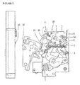
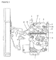
- FIGS. 1 , 2 , and 3 illustrate a broken (trip) state (or an open state), a charged state, a closed (conducted) state of the related art circuit breaker.
- a user may press an OFF button 6 to manually perform a breaking operation, or when a fault current is detected, a circuit is automatically broken (a trip operation) to change the circuit breaker into a broken state.
- an overcurrent trip relay installed outside an opening and closing mechanism 10 detects a fault current and transmits a trip control signal to an actuator, and the OFF shaft 4 is rotated in a clockwise direction by the actuator to start a breaking operation.
- a trip latch 7 is rotated in a clockwise direction so as to be released from a restrained state with respect to a main link 9 (or the trip latch 7 is rotated in a clockwise direction so as to be unlocked from the main link 9), and a breaking spring 2, which has been stretched in the closed state to charge elastic energy, discharges the elastic energy to pull a connection shaft 21 connected to one end portion of the breaking spring 2 to rotate it in a counterclockwise direction.
- the opening and closing shaft 20 is also rotated in the counterclockwise direction and the connection link is moved to the right in FIG. 3 to pull a movable contactor 30 to the right, and the movable contactor 30 is separated from the fixed contactor 40, thus completing a manual breaking operation or automatic trip operation to electrically break the circuit.
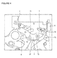
- FIGS. 4 and 5 are detailed views illustrating an operational relationship among the OFF shaft 4, the trip latch 7, and the main link 7 within the opening and closing mechanism 10 of the related art circuit breaker.
- the user may press the OFF button 6 to manually break the circuit breaker, or in case of a trip operation of the circuit breaker by an automatic trip executed when a fault current occurs, the OFF shaft 4 disposed on an upper portion of the opening and closing mechanism 10 is rotated in the clockwise direction.
- the trip latch 7 In the closed state, the trip latch 7 receiving a contact load (applied by the main link 9) in a contact portion 97 of the main link 9 and a trip latch roller 73 is rotated in the clockwise direction so as to be released (or unlocked) from the main link 9, and the contact load maintained in the contact portion of the main link 9 and the trip latch roller 73 in the closed state is changed into an open load, and as the open load is applied to the trip latch roller 73, a trip operation is substantially performed.
- EP 2 015 336 A1 discloses a circuit breaker according to the preamble of claim 1.
- circuit breaker that may reliably be changed into a broken state to cut off an electrical connection in the occurrence of an abnormal state in which the circuit breaker is not tripped in a manual manner or an auto-trip manner is required.
- the present invention provides a circuit breaker having a mechanical trip mechanism for allowing for an emergency manual trip operation in an abnormal state in which the circuit breaker is not tripped in a manual manner or auto-trip manner.
- mechanical trip mechanism when an auto-trip operation is not possibly performed in an abnormal state, mechanical trip mechanism performs an emergency manual trip operation to reliably change the circuit breaker into a broken state. Also, a condition in which the circuit breaker is not changed into a broken state by a manual operation is basically prevented, thus obtaining stability and reliability.
- the circuit breaker includes an opening and closing mechanism 10 converting a rotational motion of a plurality of links and a rotational shaft to compress a closing spring 1 and generating driving force according to elastic restoring force of the closing spring 1, an opening and closing shaft 20 connected to an opening and closing mechanism and transmitting driving force generated by the opening and closing mechanism, a fixed contactor 40, a movable contactor 30 movable to a closed state in which the movable contactor 30 is in contact with the fixed contactor 40 and a broken state in which the movable contactor 30 is separated from the fixed contactor, an overcurrent trip relay (not shown) outputting a control signal to trip the opening and closing mechanism 10 when an abnormal current is generated, and an actuator (not shown) for tripping the opening and closing mechanism by a control signal from the overcurrent trip relay.
- the configuration of the circuit breaker is the same as that of the related art circuit breaker, so a detailed configuration and operation thereof will be omitted.
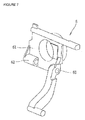
- FIGS. 6 and 7 are perspective views of an OFF button and a trip latch provided in the related art circuit breaker.
- a connection pin 71 in an assembly of a trip latch 7, two trip latches placed to be parallel in a length direction are coupled by a connection pin 71.
- a rotational shaft 72 of the tip latch is installed to penetrate the assembly of the trip lath 7, and a trip latch roller 73 is provided between the rotational shaft 72 and one connection pin 71.
- a reinforcing unit 62 is provided in a body frame 61 of an OFF button 6 on a rear surface of the OFF button 6.
- the OFF button is supported to be rotatable at a predetermined angle by a button support 64 installed to penetrate an opening 63 formed in the reinforcing unit 62.
- a contact load is applied to a contact portion 97 of the main link 9 and the trip latch roller 73, and a locked state of the main link 9 and the trip latch roller 73 is maintained.
- the trip latch roller 73 is released from a state of being locked to the main link 9, a contact load is changed into an open load, and the open load is applied to the trip latch roller 73 by the main link 9.
- the OFF shaft 4 in an upper portion of the opening and closing mechanism 10 is rotated in a clockwise direction according to a manual and auto-trip operation, and accordingly, the trip latch 7 is rotated in a clockwise direction based on the rotational shaft 72 of the trip latch 7, and thus, the trip latch roller 73 locked in the main link 9 is released.
- the trip latch 7 should be rotated in the clockwise direction based on the rotational shaft 72 of the trip latch 7 to release the trip latch roller 73 locked in the main link 9.
- the mechanical trip mechanism includes a lever member 65 formed in the OFF button 6 and a protrusion member 75 coupled to the trip latch 7.
- the lever member 65 and the protrusion member 75 are in a relationship of an operating unit and an operated unit that directly rotate the trip latch 7 in the clockwise direction when a user presses the OFF button 6 in order to change the circuit breaker into a broken state.
- the lever member 65 provided on a rear surface of the OFF button 6 is provided in the reinforcing unit 62 of the OFF button having an opening 63 through which a button support pin 64 is inserted.
- the lever member 65 is integrally formed with the OFF button 6.
- the lever member 65 integrally formed in a body frame 61 of the OFF button 6 is protruded to have a certain length such that it is parallel to a length direction of the trip latch 7.
- the lever member 65 has a rectangular parallelepiped shape overall, and a front end portion 66 of the lever member 65 has a curved surface.
- an ON button (not shown) and the OFF button 6 installed on a front portion of the circuit breaker and manually operated by the user are installed to be supported by a button support pin 64 penetrating the opening 63 of the OFF button 6.
- the OFF button is rotatable within a predetermined angle range based on the button support pin 64.
- the protrusion member 75 of the trip latch 7 is provided on one surface of the trip latch 7.
- the protrusion member 75 of the trip lath 7 is protruded to have a predetermined length toward the lever member 65 of the OFF button 6 along an axial line direction of the rotational shaft 72 of the trip latch 7.
- the protrusion member 75 is protruded to slightly exceed the lever member 65 of the OFF button in a state of being installed in the opening and closing mechanism.
- the front end portion 66 of the lever member 65 rotated together according to the rotation of the OFF button reliably pressurizes the side of the protrusion member 75.
- the protrusion member 75 may be integrally formed with the trip latch 7 or may be separately formed and coupled to the trip latch 7. When the protrusion member 75 is separately formed, the protrusion member 75 may be coupled to the trip latch 7 according to a certain method known in the art. For example, the protrusion member 75 may be coupled to the trip latch 7 according to a coupling method such as welding, caulking coupling, bolt fastening, or the like.
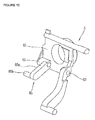
- an OFF button 6 according to a second embodiment of which is not part the present invention including a mechanical trip mechanism is illustrated.
- the lever member 65 is formed on the body frame 61 of a rear surface of the OFF button 6.
- the lever member 65 according to the second embodiment includes a first lever unit 65a and a second lever unit 65b.
- the first lever unit 65a extends to be parallel to a length direction of the trip latch 7, and the second lever unit 65b is protruded from an end portion of the first lever unit 54a toward the trip latch 7 such that it is parallel to the rotational shaft of the trip latch 7.
- the second lever unit 65b In order to allow the second lever unit 65b to rotate the trip latch 7 in a clockwise direction, the second lever unit 65b has a length sufficient to simultaneously press one edge portion 75 of the trip latch 7 or both edge portions of the trip latch 7 of the trip latch assembly. Also, in the second embodiment, preferably, the lever member 65 is integrally formed with the OFF button 6. However, the second lever unit 65b of the lever member 65 may be separately formed and coupled.
- the lever member 65 provided in the OFF button 6 and having the first lever unit 65a and the second lever unit 65b has both the functions of the mechanical trip mechanism of the lever member 65 provided in the OFF button 6 and the protrusion member 75 provided in the trip latch 7.
- the second lever unit 65b of the lever member 65 according to the second embodiment of the present invention corresponds to the protrusion member in the first embodiment as described above.
- the second lever 65b of the lever member 65 when the lever member 65 is rotated as the OFF button 6 is pressed, the second lever 65b of the lever member 65 directly presses the edge portion 74 of the trip latch 7 to rotate the trip latch 7 in a clockwise direction based on the rotational shaft 72 of the trip latch 7.
- FIGS. 11 and 12 are detailed views illustrating a trip operation of the circuit breaker by the OFF button 6 and the trip latch 7 having the mechanical trip mechanism according to an embodiment of the present invention, and the mechanical trip mechanism corresponds to the first embodiment including the lever member 65 of the OFF button and the protrusion member 75 of the trip latch 7.
- the OFF button 6 when the user manually presses the OFF button 6 provided on a front portion of the circuit breaker, the OFF button rotates based on the button support pin 64. At the same time, the lever member 65 of the OFF button is rotated. Thus, as shown in FIG. 11 , the front end portion 66 of the lever member is brought into a lateral surface of the protrusion member 75 provided in the trip latch 7 to pressurize the trip latch 7. Subsequently, in a continuous process, as shown in FIG. 12 , the lever member 65 continuously pressurizes the protrusion member 75 of the trip latch 7, and thus, the trip latch 7 is rotated in a clockwise direction.
- the trip latch roller 73 locked in the main link 9 is released, and a contact load maintained in the contact portion 97 of the main link 9 and the trip latch roller 73 in the closed state of the circuit breaker is changed into an open load and transmitted to the trip latch roller 73. Accordingly, the trip operation of the circuit breaker is certainly, reliably executed.
- the second lever unit 65b of the lever member 65 provided in the OFF button 6 directly pressurizes the edge portion 74 of the trip latch 7, and thus, the trip latch 7 is rotated in the clockwise direction.
- the trip latch roller 73 locked in the main link 9 is released, thus executing a trip operation of the circuit beaker.
- the trip latch 7 can be directly rotated in the clockwise direction in association with an operation of the OFF button 6 to release the trip latch roller 73 locked in the main link 9.
- the circuit breaker can change into a broken state through the emergency manual trip operation.
- a situation in which the circuit breaker is not changed into a broken state through a manual operation is fundamentally prevented.
Landscapes
- Breakers (AREA)
- Driving Mechanisms And Operating Circuits Of Arc-Extinguishing High-Tension Switches (AREA)
Claims (3)
- Disjoncteur, comprenant :un contacteur fixe (40) relié à un circuit ;un contacteur mobile (30) pouvant passer à un état fermé où le contacteur mobile (30) est en contact avec le contacteur fixe (40) et à un état de coupure où le contacteur mobile (30) est séparé du contacteur fixe (40) ;un mécanisme d'ouverture et de fermeture (10) configuré pour convertir un mouvement de rotation d'une pluralité de liaisons, et un arbre de rotation pour permettre au contacteur mobile (30) d'être mis en contact avec le contacteur fixe (40) ou être séparé de celui-ci ;un arbre d'ARRET (4) étudié pour tourner afin de lancer une opération de coupure du disjoncteur ;en ensemble de verrous de déclenchement (7) verrouillé sur, ou déverrouillé d'une liaison principale (9) fournie dans le mécanisme d'ouverture et de fermeture (10), l'ensemble de verrous de déclenchement (7), lorsque verrouillé sur la liaison principale (9), étant étudié pour tourner afin d'être déverrouillé de la liaison principale (9) lorsque l'on fait tourner l'arbre d'ARRET (4),un arbre de rotation (72) étudié pour pénétrer à l'intérieur de l'ensemble de verrous de déclenchement (7) de manière à être un axe de rotation de l'ensemble de verrous de déclenchement, etun bouton d'ARRET (6) configuré pour faire tourner le verrou de déclenchement (7) afin de déverrouiller le verrou de déclenchement (7) de la liaison principale (9) lorsqu'il est enfoncé manuellement, caractérisé en ce quel'ensemble de verrous de déclenchement (7) possède deux verrous de déclenchement disposés de manière à être parallèles dans une direction de longueur de l'ensemble de verrous de déclenchement (7) et couplés grâce à une broche de connexion (71),dans lequel le bouton d'ARRET (6) comprend un élément de levier (65) formé intégralement avec le bouton d'ARRET (6) pour faire tourner le verrou de déclenchement (7),et dans lequel une surface de l'un des deux verrous de déclenchement de l'ensemble de verrous de déclenchement (7) comprend un élément protubérant (75) ayant une longueur prédéterminée vers l'élément de levier (65) le long d'une direction de ligne axiale de l'arbre de rotation (72),et dans lequel l'élément protubérant (75) est étudié pour être pressé par l'élément de levier (65) lorsque le bouton d'ARRET (6) est enfoncé, dans lequel l'ensemble de verrous de déclenchement (7) est mis en rotation et est déverrouillé de la liaison principale (9) et le disjoncteur passant à un état de coupure.
- Disjoncteur selon la revendication 1, dans lequel l'élément protubérant (75) est protubérant de manière à légèrement dépasser l'élément de levier (65) du bouton d'ARRET dans un état d'installation dans le mécanisme d'ouverture et de fermeture.
- Disjoncteur selon la revendication 1, dans lequel l'élément protubérant (75) est soit intégralement formé avec le verrou de déclenchement (7), soit formé séparément et couplé au verrou de déclenchement (7).
Applications Claiming Priority (1)
| Application Number | Priority Date | Filing Date | Title |
|---|---|---|---|
| KR20110147818A KR101278501B1 (ko) | 2011-12-30 | 2011-12-30 | 기계적 트립 기구를 구비한 회로 차단기 |
Publications (2)
| Publication Number | Publication Date |
|---|---|
| EP2610882A1 EP2610882A1 (fr) | 2013-07-03 |
| EP2610882B1 true EP2610882B1 (fr) | 2015-09-30 |
Family
ID=47458768
Family Applications (1)
| Application Number | Title | Priority Date | Filing Date |
|---|---|---|---|
| EP12199560.9A Not-in-force EP2610882B1 (fr) | 2011-12-30 | 2012-12-28 | Disjoncteur doté d'un mécanisme de déclenchement mécanique |
Country Status (7)
| Country | Link |
|---|---|
| US (1) | US8975546B2 (fr) |
| EP (1) | EP2610882B1 (fr) |
| JP (1) | JP5711205B2 (fr) |
| KR (1) | KR101278501B1 (fr) |
| CN (1) | CN103187212B (fr) |
| BR (1) | BR102012033766A2 (fr) |
| ES (1) | ES2556463T3 (fr) |
Families Citing this family (9)
| Publication number | Priority date | Publication date | Assignee | Title |
|---|---|---|---|---|
| DE102014110757B4 (de) * | 2014-07-29 | 2016-12-29 | Eaton Industries Austria Gmbh | Schaltgerät |
| CN104576239A (zh) * | 2015-01-05 | 2015-04-29 | 无锡新宏泰电器科技股份有限公司 | 万能式断路器操作机构自由脱扣装置 |
| KR101689531B1 (ko) * | 2015-05-12 | 2016-12-27 | 현대중공업 주식회사 | 회로차단기 |
| CN106710982B (zh) * | 2015-07-16 | 2018-09-21 | 上海良信电器股份有限公司 | 断路器操作机构的控制机构 |
| RU2716832C2 (ru) * | 2015-08-04 | 2020-03-17 | Чжэцзян Чинт Электрикс Ко., Лтд. | Рабочий механизм с накопителем энергии для выключателя |
| KR101759601B1 (ko) * | 2015-12-28 | 2017-07-31 | 엘에스산전 주식회사 | 기중 차단기용 지연시간 발생장치 |
| KR101948723B1 (ko) * | 2018-05-16 | 2019-02-15 | 엘에스산전 주식회사 | 수동 트립 메커니즘을 갖는 직류 차단기 |
| CN109727826B (zh) | 2018-12-28 | 2024-08-13 | 浙江正泰电器股份有限公司 | 小型断路器 |
| FR3105565B1 (fr) * | 2019-12-23 | 2022-01-14 | Schneider Electric Ind Sas | Appareil de coupure d’un courant électrique |
Citations (1)
| Publication number | Priority date | Publication date | Assignee | Title |
|---|---|---|---|---|
| US20110011714A1 (en) * | 2009-07-16 | 2011-01-20 | Zhejiang Trimone Electric Science & Technology Co. Ltd. | Circuit Breaker |
Family Cites Families (12)
| Publication number | Priority date | Publication date | Assignee | Title |
|---|---|---|---|---|
| JPS60257014A (ja) | 1984-06-01 | 1985-12-18 | 株式会社日立製作所 | しや断器の手動投入、引外し操作装置 |
| JPH0869734A (ja) | 1994-08-29 | 1996-03-12 | Mitsubishi Electric Corp | 遮断器の機械的インタロック装置 |
| JP3619948B2 (ja) | 1997-07-15 | 2005-02-16 | 三菱電機株式会社 | 電気機器のインターロック装置 |
| US5973278A (en) | 1998-05-07 | 1999-10-26 | Eaton Corporation | Snap acting charge/discharge and open/closed indicators displaying states of electrical switching apparatus |
| JP4186409B2 (ja) * | 2000-10-30 | 2008-11-26 | 富士電機機器制御株式会社 | 回路しゃ断器 |
| DE10320681B4 (de) * | 2003-04-30 | 2006-10-19 | Siemens Ag | Schaltschloss zum Verklinken einer Schaltwelle und elektrischer Schalter mit einem derartigen Schaltschloss |
| KR100516944B1 (ko) * | 2003-12-26 | 2005-09-23 | 엘에스산전 주식회사 | 선행 시동형 부족전압 트립장치의 연동구조 |
| KR100828931B1 (ko) | 2006-01-20 | 2008-05-13 | 주식회사 제노프릭스 | 다수의 기기제어를 위한 범용 리모콘 시스템 |
| KR100771918B1 (ko) | 2006-10-17 | 2007-11-01 | 엘에스산전 주식회사 | 기중차단기의 개폐기구 |
| KR100876408B1 (ko) | 2007-07-12 | 2008-12-31 | 엘에스산전 주식회사 | 기계적 트립 표시 기구를 갖는 기중 차단기 |
| KR100882399B1 (ko) * | 2007-08-20 | 2009-02-05 | 엘에스산전 주식회사 | 자동 풀림 링크 기구를 구비한 회로 차단기 및 이에사용되는 자동풀림 링크 기구 |
| CN202058671U (zh) * | 2011-05-27 | 2011-11-30 | 德力西电气(宁波)有限公司 | 一种断路器防回弹装置 |
-
2011
- 2011-12-30 KR KR20110147818A patent/KR101278501B1/ko not_active Expired - Fee Related
-
2012
- 2012-12-26 US US13/727,328 patent/US8975546B2/en not_active Expired - Fee Related
- 2012-12-28 BR BRBR102012033766-5A patent/BR102012033766A2/pt not_active Application Discontinuation
- 2012-12-28 CN CN201210598992.3A patent/CN103187212B/zh not_active Expired - Fee Related
- 2012-12-28 JP JP2012288083A patent/JP5711205B2/ja not_active Expired - Fee Related
- 2012-12-28 ES ES12199560.9T patent/ES2556463T3/es active Active
- 2012-12-28 EP EP12199560.9A patent/EP2610882B1/fr not_active Not-in-force
Patent Citations (1)
| Publication number | Priority date | Publication date | Assignee | Title |
|---|---|---|---|---|
| US20110011714A1 (en) * | 2009-07-16 | 2011-01-20 | Zhejiang Trimone Electric Science & Technology Co. Ltd. | Circuit Breaker |
Also Published As
| Publication number | Publication date |
|---|---|
| US8975546B2 (en) | 2015-03-10 |
| CN103187212A (zh) | 2013-07-03 |
| ES2556463T3 (es) | 2016-01-18 |
| KR101278501B1 (ko) | 2013-07-02 |
| BR102012033766A2 (pt) | 2015-05-12 |
| JP2013140799A (ja) | 2013-07-18 |
| JP5711205B2 (ja) | 2015-04-30 |
| US20130168213A1 (en) | 2013-07-04 |
| EP2610882A1 (fr) | 2013-07-03 |
| CN103187212B (zh) | 2015-10-14 |
Similar Documents
| Publication | Publication Date | Title |
|---|---|---|
| EP2610882B1 (fr) | Disjoncteur doté d'un mécanisme de déclenchement mécanique | |
| EP2028671B1 (fr) | Disjoncteur disposant d'une liaison de libération automatique | |
| EP2028672B1 (fr) | Disjoncteur avec une liaison de déverouillage automatique | |
| RU2378730C1 (ru) | Воздушный выключатель с механизмом индикации механического размыкания | |
| CN101369502B (zh) | 电气开关设备、锁闩组件及其锁闩接合度控制机构 | |
| US7973622B2 (en) | Apparatus for auxiliary contact of circuit breaker | |
| EP2355121B1 (fr) | Disjoncteur doté d'un mécanisme d'indication de cause de déclenchement | |
| EP2538424B1 (fr) | Dispositif de commutation et système de distribution de puissance correspondant | |
| JP5426516B2 (ja) | 瞬時トリップメカニズムを有する配線用遮断器 | |
| EP2028670B1 (fr) | Dispositif de chargement de ressort pour un disjoncteur à air | |
| US9129767B2 (en) | Switching system and locking device with a status indicator | |
| EP3392898B1 (fr) | Dispositif de déclenchement magnétique d'un disjoncteur à air | |
| EP1939903A1 (fr) | Mécanisme de commutation pour un disjoncteur à air et bielles de guidage correspondantes | |
| CN116313667B (zh) | 一种断路器操作机构的锁定结构 | |
| CN219759497U (zh) | 一种断路器操作机构的锁定结构 | |
| JP5217020B2 (ja) | 回路遮断器の開閉機構 | |
| KR101734229B1 (ko) | 회로 차단기의 트립 구동 감지 유닛 | |
| JP7331803B2 (ja) | 遮断器 | |
| CN221101987U (zh) | 断路器上的附件装置和操作机构 | |
| KR101689531B1 (ko) | 회로차단기 | |
| JP2009259609A (ja) | 回路遮断器の開閉機構 | |
| US8669485B2 (en) | Reversal prevention of a stored energy mechanism in an electrical switching apparatus |
Legal Events
| Date | Code | Title | Description |
|---|---|---|---|
| PUAI | Public reference made under article 153(3) epc to a published international application that has entered the european phase |
Free format text: ORIGINAL CODE: 0009012 |
|
| AK | Designated contracting states |
Kind code of ref document: A1 Designated state(s): AL AT BE BG CH CY CZ DE DK EE ES FI FR GB GR HR HU IE IS IT LI LT LU LV MC MK MT NL NO PL PT RO RS SE SI SK SM TR |
|
| AX | Request for extension of the european patent |
Extension state: BA ME |
|
| RIN1 | Information on inventor provided before grant (corrected) |
Inventor name: YANG, HONG IK Inventor name: KIM, JONG DOO Inventor name: AHN, KIL YOUNG |
|
| 17P | Request for examination filed |
Effective date: 20140103 |
|
| RBV | Designated contracting states (corrected) |
Designated state(s): AL AT BE BG CH CY CZ DE DK EE ES FI FR GB GR HR HU IE IS IT LI LT LU LV MC MK MT NL NO PL PT RO RS SE SI SK SM TR |
|
| 17Q | First examination report despatched |
Effective date: 20140220 |
|
| GRAP | Despatch of communication of intention to grant a patent |
Free format text: ORIGINAL CODE: EPIDOSNIGR1 |
|
| INTG | Intention to grant announced |
Effective date: 20150520 |
|
| GRAS | Grant fee paid |
Free format text: ORIGINAL CODE: EPIDOSNIGR3 |
|
| GRAA | (expected) grant |
Free format text: ORIGINAL CODE: 0009210 |
|
| AK | Designated contracting states |
Kind code of ref document: B1 Designated state(s): AL AT BE BG CH CY CZ DE DK EE ES FI FR GB GR HR HU IE IS IT LI LT LU LV MC MK MT NL NO PL PT RO RS SE SI SK SM TR |
|
| REG | Reference to a national code |
Ref country code: CH Ref legal event code: EP Ref country code: GB Ref legal event code: FG4D |
|
| REG | Reference to a national code |
Ref country code: AT Ref legal event code: REF Ref document number: 752853 Country of ref document: AT Kind code of ref document: T Effective date: 20151015 |
|
| REG | Reference to a national code |
Ref country code: IE Ref legal event code: FG4D |
|
| REG | Reference to a national code |
Ref country code: DE Ref legal event code: R096 Ref document number: 602012011082 Country of ref document: DE |
|
| REG | Reference to a national code |
Ref country code: FR Ref legal event code: PLFP Year of fee payment: 4 |
|
| REG | Reference to a national code |
Ref country code: ES Ref legal event code: FG2A Ref document number: 2556463 Country of ref document: ES Kind code of ref document: T3 Effective date: 20160118 |
|
| PG25 | Lapsed in a contracting state [announced via postgrant information from national office to epo] |
Ref country code: NO Free format text: LAPSE BECAUSE OF FAILURE TO SUBMIT A TRANSLATION OF THE DESCRIPTION OR TO PAY THE FEE WITHIN THE PRESCRIBED TIME-LIMIT Effective date: 20151230 Ref country code: LV Free format text: LAPSE BECAUSE OF FAILURE TO SUBMIT A TRANSLATION OF THE DESCRIPTION OR TO PAY THE FEE WITHIN THE PRESCRIBED TIME-LIMIT Effective date: 20150930 Ref country code: LT Free format text: LAPSE BECAUSE OF FAILURE TO SUBMIT A TRANSLATION OF THE DESCRIPTION OR TO PAY THE FEE WITHIN THE PRESCRIBED TIME-LIMIT Effective date: 20150930 Ref country code: GR Free format text: LAPSE BECAUSE OF FAILURE TO SUBMIT A TRANSLATION OF THE DESCRIPTION OR TO PAY THE FEE WITHIN THE PRESCRIBED TIME-LIMIT Effective date: 20151231 Ref country code: FI Free format text: LAPSE BECAUSE OF FAILURE TO SUBMIT A TRANSLATION OF THE DESCRIPTION OR TO PAY THE FEE WITHIN THE PRESCRIBED TIME-LIMIT Effective date: 20150930 |
|
| REG | Reference to a national code |
Ref country code: NL Ref legal event code: MP Effective date: 20150930 |
|
| REG | Reference to a national code |
Ref country code: LT Ref legal event code: MG4D |
|
| REG | Reference to a national code |
Ref country code: AT Ref legal event code: MK05 Ref document number: 752853 Country of ref document: AT Kind code of ref document: T Effective date: 20150930 |
|
| PG25 | Lapsed in a contracting state [announced via postgrant information from national office to epo] |
Ref country code: RS Free format text: LAPSE BECAUSE OF FAILURE TO SUBMIT A TRANSLATION OF THE DESCRIPTION OR TO PAY THE FEE WITHIN THE PRESCRIBED TIME-LIMIT Effective date: 20150930 Ref country code: SE Free format text: LAPSE BECAUSE OF FAILURE TO SUBMIT A TRANSLATION OF THE DESCRIPTION OR TO PAY THE FEE WITHIN THE PRESCRIBED TIME-LIMIT Effective date: 20150930 Ref country code: HR Free format text: LAPSE BECAUSE OF FAILURE TO SUBMIT A TRANSLATION OF THE DESCRIPTION OR TO PAY THE FEE WITHIN THE PRESCRIBED TIME-LIMIT Effective date: 20150930 |
|
| PG25 | Lapsed in a contracting state [announced via postgrant information from national office to epo] |
Ref country code: SK Free format text: LAPSE BECAUSE OF FAILURE TO SUBMIT A TRANSLATION OF THE DESCRIPTION OR TO PAY THE FEE WITHIN THE PRESCRIBED TIME-LIMIT Effective date: 20150930 Ref country code: EE Free format text: LAPSE BECAUSE OF FAILURE TO SUBMIT A TRANSLATION OF THE DESCRIPTION OR TO PAY THE FEE WITHIN THE PRESCRIBED TIME-LIMIT Effective date: 20150930 Ref country code: NL Free format text: LAPSE BECAUSE OF FAILURE TO SUBMIT A TRANSLATION OF THE DESCRIPTION OR TO PAY THE FEE WITHIN THE PRESCRIBED TIME-LIMIT Effective date: 20150930 Ref country code: CZ Free format text: LAPSE BECAUSE OF FAILURE TO SUBMIT A TRANSLATION OF THE DESCRIPTION OR TO PAY THE FEE WITHIN THE PRESCRIBED TIME-LIMIT Effective date: 20150930 Ref country code: IS Free format text: LAPSE BECAUSE OF FAILURE TO SUBMIT A TRANSLATION OF THE DESCRIPTION OR TO PAY THE FEE WITHIN THE PRESCRIBED TIME-LIMIT Effective date: 20160130 |
|
| PG25 | Lapsed in a contracting state [announced via postgrant information from national office to epo] |
Ref country code: BE Free format text: LAPSE BECAUSE OF NON-PAYMENT OF DUE FEES Effective date: 20151231 Ref country code: RO Free format text: LAPSE BECAUSE OF FAILURE TO SUBMIT A TRANSLATION OF THE DESCRIPTION OR TO PAY THE FEE WITHIN THE PRESCRIBED TIME-LIMIT Effective date: 20150930 Ref country code: PT Free format text: LAPSE BECAUSE OF FAILURE TO SUBMIT A TRANSLATION OF THE DESCRIPTION OR TO PAY THE FEE WITHIN THE PRESCRIBED TIME-LIMIT Effective date: 20160201 Ref country code: PL Free format text: LAPSE BECAUSE OF FAILURE TO SUBMIT A TRANSLATION OF THE DESCRIPTION OR TO PAY THE FEE WITHIN THE PRESCRIBED TIME-LIMIT Effective date: 20150930 Ref country code: AT Free format text: LAPSE BECAUSE OF FAILURE TO SUBMIT A TRANSLATION OF THE DESCRIPTION OR TO PAY THE FEE WITHIN THE PRESCRIBED TIME-LIMIT Effective date: 20150930 |
|
| REG | Reference to a national code |
Ref country code: DE Ref legal event code: R097 Ref document number: 602012011082 Country of ref document: DE |
|
| PG25 | Lapsed in a contracting state [announced via postgrant information from national office to epo] |
Ref country code: MC Free format text: LAPSE BECAUSE OF FAILURE TO SUBMIT A TRANSLATION OF THE DESCRIPTION OR TO PAY THE FEE WITHIN THE PRESCRIBED TIME-LIMIT Effective date: 20150930 Ref country code: LU Free format text: LAPSE BECAUSE OF FAILURE TO SUBMIT A TRANSLATION OF THE DESCRIPTION OR TO PAY THE FEE WITHIN THE PRESCRIBED TIME-LIMIT Effective date: 20151228 |
|
| REG | Reference to a national code |
Ref country code: CH Ref legal event code: PL |
|
| PLBE | No opposition filed within time limit |
Free format text: ORIGINAL CODE: 0009261 |
|
| STAA | Information on the status of an ep patent application or granted ep patent |
Free format text: STATUS: NO OPPOSITION FILED WITHIN TIME LIMIT |
|
| PG25 | Lapsed in a contracting state [announced via postgrant information from national office to epo] |
Ref country code: DK Free format text: LAPSE BECAUSE OF FAILURE TO SUBMIT A TRANSLATION OF THE DESCRIPTION OR TO PAY THE FEE WITHIN THE PRESCRIBED TIME-LIMIT Effective date: 20150930 |
|
| 26N | No opposition filed |
Effective date: 20160701 |
|
| REG | Reference to a national code |
Ref country code: IE Ref legal event code: MM4A |
|
| REG | Reference to a national code |
Ref country code: FR Ref legal event code: PLFP Year of fee payment: 5 |
|
| PG25 | Lapsed in a contracting state [announced via postgrant information from national office to epo] |
Ref country code: IE Free format text: LAPSE BECAUSE OF NON-PAYMENT OF DUE FEES Effective date: 20151228 Ref country code: LI Free format text: LAPSE BECAUSE OF NON-PAYMENT OF DUE FEES Effective date: 20151231 Ref country code: CH Free format text: LAPSE BECAUSE OF NON-PAYMENT OF DUE FEES Effective date: 20151231 |
|
| PG25 | Lapsed in a contracting state [announced via postgrant information from national office to epo] |
Ref country code: SI Free format text: LAPSE BECAUSE OF FAILURE TO SUBMIT A TRANSLATION OF THE DESCRIPTION OR TO PAY THE FEE WITHIN THE PRESCRIBED TIME-LIMIT Effective date: 20150930 |
|
| PG25 | Lapsed in a contracting state [announced via postgrant information from national office to epo] |
Ref country code: BE Free format text: LAPSE BECAUSE OF FAILURE TO SUBMIT A TRANSLATION OF THE DESCRIPTION OR TO PAY THE FEE WITHIN THE PRESCRIBED TIME-LIMIT Effective date: 20150930 |
|
| PG25 | Lapsed in a contracting state [announced via postgrant information from national office to epo] |
Ref country code: SM Free format text: LAPSE BECAUSE OF FAILURE TO SUBMIT A TRANSLATION OF THE DESCRIPTION OR TO PAY THE FEE WITHIN THE PRESCRIBED TIME-LIMIT Effective date: 20150930 Ref country code: BG Free format text: LAPSE BECAUSE OF FAILURE TO SUBMIT A TRANSLATION OF THE DESCRIPTION OR TO PAY THE FEE WITHIN THE PRESCRIBED TIME-LIMIT Effective date: 20150930 Ref country code: HU Free format text: LAPSE BECAUSE OF FAILURE TO SUBMIT A TRANSLATION OF THE DESCRIPTION OR TO PAY THE FEE WITHIN THE PRESCRIBED TIME-LIMIT; INVALID AB INITIO Effective date: 20121228 |
|
| PG25 | Lapsed in a contracting state [announced via postgrant information from national office to epo] |
Ref country code: CY Free format text: LAPSE BECAUSE OF FAILURE TO SUBMIT A TRANSLATION OF THE DESCRIPTION OR TO PAY THE FEE WITHIN THE PRESCRIBED TIME-LIMIT Effective date: 20150930 |
|
| PG25 | Lapsed in a contracting state [announced via postgrant information from national office to epo] |
Ref country code: MT Free format text: LAPSE BECAUSE OF FAILURE TO SUBMIT A TRANSLATION OF THE DESCRIPTION OR TO PAY THE FEE WITHIN THE PRESCRIBED TIME-LIMIT Effective date: 20150930 |
|
| REG | Reference to a national code |
Ref country code: FR Ref legal event code: PLFP Year of fee payment: 6 |
|
| PG25 | Lapsed in a contracting state [announced via postgrant information from national office to epo] |
Ref country code: MK Free format text: LAPSE BECAUSE OF FAILURE TO SUBMIT A TRANSLATION OF THE DESCRIPTION OR TO PAY THE FEE WITHIN THE PRESCRIBED TIME-LIMIT Effective date: 20150930 Ref country code: TR Free format text: LAPSE BECAUSE OF FAILURE TO SUBMIT A TRANSLATION OF THE DESCRIPTION OR TO PAY THE FEE WITHIN THE PRESCRIBED TIME-LIMIT Effective date: 20150930 |
|
| REG | Reference to a national code |
Ref country code: FR Ref legal event code: PLFP Year of fee payment: 7 |
|
| PG25 | Lapsed in a contracting state [announced via postgrant information from national office to epo] |
Ref country code: AL Free format text: LAPSE BECAUSE OF FAILURE TO SUBMIT A TRANSLATION OF THE DESCRIPTION OR TO PAY THE FEE WITHIN THE PRESCRIBED TIME-LIMIT Effective date: 20150930 |
|
| PGFP | Annual fee paid to national office [announced via postgrant information from national office to epo] |
Ref country code: FR Payment date: 20180910 Year of fee payment: 7 |
|
| PGFP | Annual fee paid to national office [announced via postgrant information from national office to epo] |
Ref country code: DE Payment date: 20180905 Year of fee payment: 7 |
|
| PGFP | Annual fee paid to national office [announced via postgrant information from national office to epo] |
Ref country code: GB Payment date: 20181005 Year of fee payment: 7 Ref country code: IT Payment date: 20181210 Year of fee payment: 7 |
|
| PGFP | Annual fee paid to national office [announced via postgrant information from national office to epo] |
Ref country code: ES Payment date: 20190116 Year of fee payment: 7 |
|
| REG | Reference to a national code |
Ref country code: DE Ref legal event code: R119 Ref document number: 602012011082 Country of ref document: DE |
|
| GBPC | Gb: european patent ceased through non-payment of renewal fee |
Effective date: 20191228 |
|
| PG25 | Lapsed in a contracting state [announced via postgrant information from national office to epo] |
Ref country code: FR Free format text: LAPSE BECAUSE OF NON-PAYMENT OF DUE FEES Effective date: 20191231 Ref country code: IT Free format text: LAPSE BECAUSE OF NON-PAYMENT OF DUE FEES Effective date: 20191228 Ref country code: DE Free format text: LAPSE BECAUSE OF NON-PAYMENT OF DUE FEES Effective date: 20200701 Ref country code: GB Free format text: LAPSE BECAUSE OF NON-PAYMENT OF DUE FEES Effective date: 20191228 |
|
| REG | Reference to a national code |
Ref country code: ES Ref legal event code: FD2A Effective date: 20210524 |
|
| PG25 | Lapsed in a contracting state [announced via postgrant information from national office to epo] |
Ref country code: ES Free format text: LAPSE BECAUSE OF NON-PAYMENT OF DUE FEES Effective date: 20191229 |