EP2610959A2 - Glasantenne für Fahrzeuge - Google Patents
Glasantenne für Fahrzeuge Download PDFInfo
- Publication number
- EP2610959A2 EP2610959A2 EP12199525.2A EP12199525A EP2610959A2 EP 2610959 A2 EP2610959 A2 EP 2610959A2 EP 12199525 A EP12199525 A EP 12199525A EP 2610959 A2 EP2610959 A2 EP 2610959A2
- Authority
- EP
- European Patent Office
- Prior art keywords
- antenna
- vertical element
- dab
- slit
- glass
- Prior art date
- Legal status (The legal status is an assumption and is not a legal conclusion. Google has not performed a legal analysis and makes no representation as to the accuracy of the status listed.)
- Withdrawn
Links
- 239000011521 glass Substances 0.000 title claims abstract description 39
- 230000035945 sensitivity Effects 0.000 claims abstract description 47
- 230000000052 comparative effect Effects 0.000 description 16
- 238000004088 simulation Methods 0.000 description 10
- 238000011156 evaluation Methods 0.000 description 8
- 238000005259 measurement Methods 0.000 description 2
- 230000008878 coupling Effects 0.000 description 1
- 238000010168 coupling process Methods 0.000 description 1
- 238000005859 coupling reaction Methods 0.000 description 1
- 230000000694 effects Effects 0.000 description 1
- 230000000149 penetrating effect Effects 0.000 description 1
- 238000004904 shortening Methods 0.000 description 1
Images


Classifications
-
- H—ELECTRICITY
- H01—ELECTRIC ELEMENTS
- H01Q—ANTENNAS, i.e. RADIO AERIALS
- H01Q1/00—Details of, or arrangements associated with, antennas
- H01Q1/12—Supports; Mounting means
- H01Q1/1271—Supports; Mounting means for mounting on windscreens
-
- H—ELECTRICITY
- H01—ELECTRIC ELEMENTS
- H01Q—ANTENNAS, i.e. RADIO AERIALS
- H01Q5/00—Arrangements for simultaneous operation of antennas on two or more different wavebands, e.g. dual-band or multi-band arrangements
- H01Q5/40—Imbricated or interleaved structures; Combined or electromagnetically coupled arrangements, e.g. comprising two or more non-connected fed radiating elements
Definitions
- the present invention relates to a vehicular glass antenna in which a digital audio broadcasting (DAB) antenna having good reception characteristics is installed.
- DAB digital audio broadcasting
- Glass antennas in which a DAB antenna is installed are known from, e.g., Japanese Patent Application Laid-Open Publication Nos. 2010-081567 ( JP 2010-081567 A ), 2010-124444 ( JP 2010-124444 A ) and 2010-154504 ( JP 2010-154504 A ).
- JP 2010-081567 A an L-shaped DAB antenna is positioned alongside an AM antenna in a side-by-side arrangement with the AM antenna.
- JP 2010-124444 A and JP 2010-154504 A disclose a glass antenna in which a DAB antenna is incorporated within an AM antenna.
- the area on which the AM antenna is arranged is limited by the presence of the DAB antenna, and the reception sensitivity of the AM antenna is therefore reduced.
- the reception sensitivity of the AM antenna increases in commensurate fashion with the increased arrangement surface area of the antenna, but arranging a DAB antenna causes reception sensitivity to be reduced by an amount commensurate with the reduced arrangement surface area of the AM antenna.
- An object of the present invention is to provide a vehicular glass antenna in which a DAB antenna or the like provided with good receiving characteristics has been arranged without a reduction in the reception sensitivity of the AM antenna.
- a vehicular glass antenna which comprises: a first antenna having a plurality of horizontal elements and vertical elements, and a second antenna capacitatively coupled with a topmost one of the horizontal elements of the first antenna, the second antenna being arranged in an upper part of a region in which the first antenna is mounted, wherein the first antenna includes the topmost horizontal element, a first vertical element in held contact with the horizontal element, and a second vertical element, the first vertical element and the second vertical element are disposed so as to be substantially in parallel across a gap for which a reception sensitivity of each of the first antenna and the second antenna is set to be in an optimal range, and a slit having a predetermined height is formed by the gap, and an electrical connection is established at a bottommost end of each of the first vertical element and the second vertical element.
- the slit thus formed in the first antenna capacitatively couples with the second antenna, whereby a portion of the first antenna can be made to operate as the second antenna. Accordingly, the presence of the second antenna does not limit the arrangement surface area of the first antenna, and the second antenna can be arranged without a reduction in the sensitivity of the first antenna.
- the gap is selected to lie within a range of 2 to 20 mm.
- a predetermined gap is prescribed by a range in which the receiving sensitivities of the first antenna and the second antenna are both optimal. It was found by evaluation carried out by the inventor that optimal reception sensitivity can be obtained in a range of 2 to 20 (mm) for the first antenna and the second antenna, and that adjustments can be made in this range.
- the predetermined height is a size adjusted so as to be substantially 1/4 ⁇ or less.
- the inventor has evaluated this to be, e.g., 254 (mm).
- the first vertical element for forming the slit is arranged at an interval of 0 to 100 mm with reference to a virtual line extending vertically from a power feed terminal of the second antenna arranged on the upper side of the region in which the first antenna is mounted.
- arranging the first vertical element at an interval of 0 to 100 (mm) allows the reception sensitivity of the second antenna to be the same as if the first antenna were not present.
- the first vertical element for forming the slit is arranged at an interval of 0 to 60 mm with reference to a virtual line extending vertically from a power feed terminal of the second antenna.
- arranging the first vertical element at an interval of 0 to 60 (mm) allows the reception sensitivity of the second antenna to be at least the same as if the first antenna were not present.
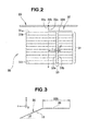
- the vehicular glass antenna 30 is mounted on the rear glass 15 of a vehicle 10, and includes an AM antenna 31 (first antenna) and a DAB antenna 32 (second antenna).
- Reference numeral 34 is a defogger.
- the vehicle 10 comprises a front glass 13 provided between left and right front pillars 12L, 12R of a vehicle body 11, a rear glass 15 provided between left and right rear pillars 14L, 14R, left and right front door glass 17L, 17R elevatably mounted in left and right front doors 16L, 16R, and left and right rear door glass 19L, 19R elevatably mounted in left and right rear doors 18L, 18R.
- Reference numeral 20 is a roof.
- the glass antenna 30 for a vehicle shown in the present embodiment is an antenna designed for receiving: band III, which is 174 to 240 MHz in DAB; two different frequency bands in the L-band of 1452 to 1492 MHz; and AM band radio waves.
- the glass antenna 30 for a vehicle includes an AM antenna 31 (first antenna) and a DAB antenna 32 (second antenna).
- the DAB antenna 32 is composed of a power feed terminal 32a (hot terminal) arranged above the region in which the AM antenna 31 is mounted, a single vertical element 32c extending from the power feed terminal 32a as a starting end toward the AM antenna 31, and a single horizontal element 32d extending substantially parallel to twelve horizontal elements 31 a to 311 constituting the AM antenna 31 from the other end of the vertical element 32c.
- the DAB antenna 32 is configured so as to be capacitatively coupled to the horizontal element 31 a positioned in the topmost part of the AM antenna 31.
- the AM antenna 31 has, among the plurality of horizontal elements 31 a to 311 constituting the AM antenna 31, a horizontal element 31 a positioned in the topmost part, a first vertical element 33a in contact with the horizontal element 31 a, and a second vertical element 33b.
- the first vertical element 33a and the second vertical element 33b are disposed substantially in parallel having a gap "d" for which the receiving sensitivities of the AM antenna 31 and the DAB antenna 32 are both prescribed to be in an optimal range, and a slit 33 having a fixed length is formed by this gap "d.”
- the lowermost ends of the first vertical element 33a and the second vertical element 33b are electrically connected.
- the power feed terminal 32b (ground terminal) of the DAB antenna 32 is connected to the roof 20.
- the slit 33 formed in the AM antenna 31 capacitatively couples with the DAB antenna 32, and can be made to operate as a DAB antenna 32 including the slit 33.
- the DAB antenna 32 can thus be designed without a reduction in the sensitivity of the AM antenna 31 because the mounting surface area of the AM antenna 31 is not required to be reduced for the DAB antenna 32.
- the basis for the above is described below.
- the inventor carried out a simulation using a frequency of 174 to 240 MHz, which is the receiving range of the DAB antenna 32.
- the slope angle ⁇ of the rear glass 15 was set to 30 degrees as a simulation condition, as shown in Fig. 3 with a portion of the vehicle as the right-side surface.
- the ground terminal of the antenna is connected to the roof 20, and the "y" direction of the roof 20 is infinite.
- the directivity and sensitivity of vertically polarized waves of an xy plane ( Fig. 3 ) were obtained for each frequency at intervals of 3 MHz, and the average sensitivity at all frequencies was calculated.
- the roof 20 is infinite ( ⁇ ), but is depicted as being finite in Figs. 4A and 4B in order to show the antenna structure.
- Table 1 Average sensitivity (dBd)c Without AM With AM -13.7 -21.1
- the average sensitivity was -13.7 (dBd) for the case of comparative example 1 in which the AM antenna 31 was not present; and the average sensitivity was -21.1 (dBd) for the case of comparative example 2 in which the AM antenna 31 was present.
- the antenna length is adjusted so that the average sensitivity of the DAB antenna 32 is maximum without the presence of an AM antenna. Therefore, the ideal sensitivity is obtained because an AM antenna is not present.
- the DAB antenna 32 is bent in an L-shape in order to avoid penetrating the mounting region of the AM antenna 31, and the average sensitivity is less than the comparative example 1. This is due to the fact that an antenna element ideal for vertically polarized waves cannot be formed in the vertical direction.
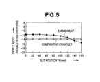
- the term "slit position” refers to the distance from the power feed point (hot terminal 32a) of the DAB antenna 32 to the first vertical element 33a of the AM antenna 31 with reference to a vertically extending virtual line "x.”
- Table 2 Average sensitivity (dBd) Position (mm) Embodiment Comparative example1 0 -11.6 -13.7 20 -11.6 -13.7 40 -11.6 -13.7 60 -11.7 -13.7 80 -11.9 -13.7 100 -12.3 -13.7 120 -12.9 -13.7 140 -14.4 -13.7 160 -15.4 -13.7
- the range that can be used as the slit position "l" where the average sensitivity is equal to or greater than that of comparative example 1 is 0 to 130 (mm) in the present embodiment, but the range is more preferably 0 to 100 (mm), and is most preferably 0 to 60 (mm).
- the average sensitivity is -11.6 (dBd) in the embodiment in comparison with -13.7 (dBd) in comparative example 1.
- the same effect can be obtained by providing, in place of the slit 33, a vertical element that traverses from the horizontal element 31 a positioned in the topmost part of the AM antenna 31 to the horizontal element 31l positioned in the bottommost part.
- a vertical element it is known from experience that FM sensitivity may be reduced when, e.g., the AM antenna 31 is used in a shared fashion as an FM antenna, or even when separate elements are used and the two are capacitatively coupled, and such configurations are not preferred due to the difficulty in designing the FM antenna and the DAB antenna 32.
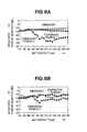
- Example 2 Present Em bodiment 174 -14.4 -13.8 -13.4 177 -14.1 -13.8 -13.1 180 -13.7 -13.1 -12.8 183 -13.4 -12.6 -12.5 186 -13.2 -11.9 -12.3 189 -13.1 -12.5 -12.1 192 -12.9 -15.8 -12.0 195 -12.9 -18.6 -11.9 198 -12.9 -20.0 -11.8 201 -12.9 -25.1 -11.8 204 -13.0 -23.2 -11.7 207 -13.1 -24.4 -11.6 210 -13.2 -27.8 -11.5 213 -13.4 -27.4 -11.4 216 -13.5 -28.1 -11.3 219 -13.7 -29.1 -11.2 222 -13.9 -26.1 -11.0 225 -14.0 -25.5 -10.9 228 -14.2 -24.4 -10.7 231 -14.4 -23.9 -10.6 234 -14.6 -23.3 -10.5 237 -14.7 -22.9
- Example 1 Comp. Example 2 Present Embodiment 174 -14.7 -15.2 -12.5 177 -14.5 -14.9 -10.9 180 -14.7 -15.5 -12.4 183 -13.5 -15.3 -13.6 186 -13.2 -14.0 -12.1 189 -12.8 -12.0 -11.5 192 -12.5 -12.7 -10.9 195 -12.5 -16.8 -11.4 198 -14.3 -18.4 -13.0 201 -11.5 -21.3 -10.1 204 -11.0 -18.6 -10.6 207 -11.1 -18.1 -11.1 210 -11.2 -18.0 -12.5 213 -11.0 -17.6 -13.5 216 -10.5 -16.6 -13.7 219 -10.2 -16.7 -12.9 222 -11.6 -17.5 -12.4 225 -12.2 -17.9 -12.7 228 -11.7 -17.5 -12.4 231 -10.8 -16.1 -11.9 234 -9.9 -14.8 -10.3 237 -11.1
- Fig. 6A is a graph showing the simulation results
- Fig. 6B is a graph showing the reception sensitivity on the basis of actual measurement results. It is apparent from Figs. 6A and 6B , or Tables 3 and 4, that actual measurement results and simulation results are roughly similar. Therefore, it was confirmed that the same or better sensitivity than that of comparative example 1 shown in Fig. 4A in which an AM antenna is not present is obtained even with the presence of the AM antenna 31.
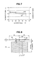
- Fig. 7 is a graph showing the sensitivity characteristics, in which the slit width "d" (mm) is plotted on the horizontal axis and the sensitivities (dBd, dBuV) of the DAB antenna 32 and the AM antenna 31, respectively, are plotted on the vertical axis.
- the term “slit width” refers to an interval "d" between the first vertical element 33a and the second vertical element 33b constituting the slit 33 in the AM antenna 31 shown in Fig. 2 .
- the slit width "d” in which the optimal sensitivity is obtained for both the DAB antenna 32 and the AM antenna 31 is in a range of 2 to 20 mm.
- the height of the slit 33 will be further described.
- the height (antenna length) of the slit 33 refers to the distance from the power feed terminal 32a (hot terminal) of the DAB antenna 32 to the horizontal element 31l positioned in the bottommost area of the AM antenna 31.
- the above-described antenna length can be adjusted by selecting the horizontal element on the bottom side (positioned in the bottommost step) among the twelve horizontal elements 31 a to 31l constituting the AM antenna 31. There may be cases in which the antenna length is ⁇ /4 or less when a sufficient antenna length cannot be used in terms of designing the AM antenna 31.
- the glass antenna 30 for a vehicle of the present embodiment includes an AM antenna 31 composed of a plurality of horizontal elements 31 a to 31l and first and second vertical elements 33a, 33b, and a DAB antenna 32 for capacitatively coupling with the horizontal element 31 a positioned in the topmost part of the AM antenna 31, the DAB antenna being arranged in an upper part of a region in which the AM antenna 31 is mounted.
- the AM antenna 31 has, among the plurality of horizontal elements 31 a to 31l, a horizontal element 31 a positioned in the upper part, a first vertical element 33a in contact with the horizontal element 31 a, and a second vertical element 33b; the first vertical element 33a and the second vertical element 33b are disposed so as to be substantially in parallel across a gap "d" for which the reception sensitivity of each of the AM antenna 31 and the DAB antenna 32 is prescribed to be in an optimal range, and a slit 33 having a fixed height is formed by the gap "d"; and an electrical connection is established at a bottommost end of each of the first vertical element 33a and the second vertical element 33b.
- the slit 33 thus formed in the AM antenna 31 capacitatively couples with the DAB antenna 32, whereby the slit 33 can operate as the DAB antenna 32. Accordingly, the presence of the DAB antenna 32 does not limit the arrangement surface area of the AM antenna 31, and the DAB antenna 32 can therefore be designed without a reduction in the sensitivity of the AM antenna 31.
- the slit width (an interval "d" between the first vertical element 33a and the second vertical element 33b of the AM antenna 31) is prescribed so that the receiving sensitivities of the AM antenna 31 and the DAB antenna 32 are both in an optimal range. It was found by evaluation carried out by the inventor that optimal reception sensitivity can be obtained in a range of 2 to 20 mm, and that adjustments can be made in this range.
- the same sensitivity can be obtained as if the AM antenna 31 were not present when the position of the slit 33, which is indicated by the distance from the power feed terminal (hot terminal 32a) of the DAB antenna 32 to the first vertical element 33a of the AM antenna 31 with reference to a vertically extending virtual line "x", is in a range of 0 to 100 mm (more preferably 0 to 60 mm).
- a glass antenna 30 for a vehicle in which a DAB antenna or the like provided with good receiving characteristics is arranged without a reduction in the reception sensitivity of the AM antenna.
Landscapes
- Physics & Mathematics (AREA)
- Electromagnetism (AREA)
- Details Of Aerials (AREA)
- Support Of Aerials (AREA)
Applications Claiming Priority (1)
| Application Number | Priority Date | Filing Date | Title |
|---|---|---|---|
| JP2011287523A JP5738177B2 (ja) | 2011-12-28 | 2011-12-28 | 車両用ガラスアンテナ |
Publications (2)
| Publication Number | Publication Date |
|---|---|
| EP2610959A2 true EP2610959A2 (de) | 2013-07-03 |
| EP2610959A3 EP2610959A3 (de) | 2013-10-30 |
Family
ID=47623877
Family Applications (1)
| Application Number | Title | Priority Date | Filing Date |
|---|---|---|---|
| EP12199525.2A Withdrawn EP2610959A3 (de) | 2011-12-28 | 2012-12-27 | Glasantenne für Fahrzeuge |
Country Status (2)
| Country | Link |
|---|---|
| EP (1) | EP2610959A3 (de) |
| JP (1) | JP5738177B2 (de) |
Cited By (1)
| Publication number | Priority date | Publication date | Assignee | Title |
|---|---|---|---|---|
| US10541463B2 (en) | 2016-06-03 | 2020-01-21 | Mazda Motor Corporation | Glass antenna |
Families Citing this family (1)
| Publication number | Priority date | Publication date | Assignee | Title |
|---|---|---|---|---|
| JP6428258B2 (ja) * | 2014-12-26 | 2018-11-28 | Agc株式会社 | 車両用ガラスアンテナ |
Citations (3)
| Publication number | Priority date | Publication date | Assignee | Title |
|---|---|---|---|---|
| JP2010081567A (ja) | 2008-08-29 | 2010-04-08 | Asahi Glass Co Ltd | 車両用ガラスアンテナ及び車両用窓ガラス |
| JP2010124444A (ja) | 2008-11-21 | 2010-06-03 | Asahi Glass Co Ltd | 車両用ガラスアンテナ及び車両用窓ガラス |
| JP2010154504A (ja) | 2008-11-20 | 2010-07-08 | Asahi Glass Co Ltd | 車両用ガラスアンテナ及び車両用窓ガラス |
Family Cites Families (5)
| Publication number | Priority date | Publication date | Assignee | Title |
|---|---|---|---|---|
| EP0446684B1 (de) * | 1990-03-10 | 1995-06-21 | Flachglas Aktiengesellschaft | Kraftfahrzeugscheibe in Form einer Zweischeiben-Isolierglaseinheit mit Antennenelementen |
| JP3393638B2 (ja) * | 1997-04-11 | 2003-04-07 | 日本板硝子株式会社 | トランス伝送ガラスアンテナ |
| JP2000151248A (ja) * | 1998-11-16 | 2000-05-30 | Nippon Sheet Glass Co Ltd | 車両用ガラスアンテナ装置 |
| JP3294837B2 (ja) * | 2000-04-28 | 2002-06-24 | 日本アンテナ株式会社 | フィルムアンテナ |
| JP5023956B2 (ja) * | 2007-10-15 | 2012-09-12 | 旭硝子株式会社 | 自動車用ガラスアンテナ |
-
2011
- 2011-12-28 JP JP2011287523A patent/JP5738177B2/ja not_active Expired - Fee Related
-
2012
- 2012-12-27 EP EP12199525.2A patent/EP2610959A3/de not_active Withdrawn
Patent Citations (3)
| Publication number | Priority date | Publication date | Assignee | Title |
|---|---|---|---|---|
| JP2010081567A (ja) | 2008-08-29 | 2010-04-08 | Asahi Glass Co Ltd | 車両用ガラスアンテナ及び車両用窓ガラス |
| JP2010154504A (ja) | 2008-11-20 | 2010-07-08 | Asahi Glass Co Ltd | 車両用ガラスアンテナ及び車両用窓ガラス |
| JP2010124444A (ja) | 2008-11-21 | 2010-06-03 | Asahi Glass Co Ltd | 車両用ガラスアンテナ及び車両用窓ガラス |
Cited By (1)
| Publication number | Priority date | Publication date | Assignee | Title |
|---|---|---|---|---|
| US10541463B2 (en) | 2016-06-03 | 2020-01-21 | Mazda Motor Corporation | Glass antenna |
Also Published As
| Publication number | Publication date |
|---|---|
| JP5738177B2 (ja) | 2015-06-17 |
| EP2610959A3 (de) | 2013-10-30 |
| JP2013138294A (ja) | 2013-07-11 |
Similar Documents
| Publication | Publication Date | Title |
|---|---|---|
| US7511676B2 (en) | High frequency wave glass antenna for an automobile | |
| JP2870940B2 (ja) | 車載アンテナ | |
| US7623087B2 (en) | High-impedance substrate, antenna device and mobile radio device | |
| EP2051326B1 (de) | Glasantenne für ein Automobil | |
| EP3101733B1 (de) | Glasantenne | |
| US10965018B2 (en) | Antenna device | |
| US8111202B2 (en) | High frequency wave glass antenna for an automobile and window glass sheet for an automobile with the same | |
| JP6401835B1 (ja) | アンテナ装置 | |
| US11196154B2 (en) | Antenna device | |
| JP5141500B2 (ja) | 車両用ガラスアンテナ及び車両用窓ガラス | |
| US7671298B2 (en) | Heating line pattern structure of defogger formed on rear window glass panel of motor vehicle and rear glass panel | |
| WO2003052869A1 (en) | High-bandwidth multi-band antenna | |
| EP3163674B1 (de) | Scheibenantenne für ein fahrzeug und heckscheibenglas einschliesslich der scheibenantenne für ein fahrzeug | |
| EP2712020B1 (de) | Glasantenne und Fensterglas | |
| JP2008278481A (ja) | 自動車用高周波ガラスアンテナ及び自動車用の窓ガラス板 | |
| US20030001786A1 (en) | Antenna device and portable terminal | |
| US20060077109A1 (en) | Heating line pattern structure of defogger | |
| JP6985598B2 (ja) | アンテナ及び窓ガラス | |
| JP5738177B2 (ja) | 車両用ガラスアンテナ | |
| US20240030624A1 (en) | Antenna device | |
| WO2023068007A1 (ja) | アンテナ装置 | |
| JP2010124444A (ja) | 車両用ガラスアンテナ及び車両用窓ガラス | |
| SG188394A1 (en) | Compact multi-column antenna | |
| KR20090049513A (ko) | 무선 통신 안테나 장치 | |
| JP5953399B2 (ja) | 車両用ガラスアンテナ |
Legal Events
| Date | Code | Title | Description |
|---|---|---|---|
| PUAI | Public reference made under article 153(3) epc to a published international application that has entered the european phase |
Free format text: ORIGINAL CODE: 0009012 |
|
| AK | Designated contracting states |
Kind code of ref document: A2 Designated state(s): AL AT BE BG CH CY CZ DE DK EE ES FI FR GB GR HR HU IE IS IT LI LT LU LV MC MK MT NL NO PL PT RO RS SE SI SK SM TR |
|
| AX | Request for extension of the european patent |
Extension state: BA ME |
|
| PUAL | Search report despatched |
Free format text: ORIGINAL CODE: 0009013 |
|
| AK | Designated contracting states |
Kind code of ref document: A3 Designated state(s): AL AT BE BG CH CY CZ DE DK EE ES FI FR GB GR HR HU IE IS IT LI LT LU LV MC MK MT NL NO PL PT RO RS SE SI SK SM TR |
|
| AX | Request for extension of the european patent |
Extension state: BA ME |
|
| RIC1 | Information provided on ipc code assigned before grant |
Ipc: H01Q 5/00 20060101ALI20130926BHEP Ipc: H01Q 1/12 20060101AFI20130926BHEP |
|
| 17P | Request for examination filed |
Effective date: 20140305 |
|
| RBV | Designated contracting states (corrected) |
Designated state(s): AL AT BE BG CH CY CZ DE DK EE ES FI FR GB GR HR HU IE IS IT LI LT LU LV MC MK MT NL NO PL PT RO RS SE SI SK SM TR |
|
| 17Q | First examination report despatched |
Effective date: 20160225 |
|
| STAA | Information on the status of an ep patent application or granted ep patent |
Free format text: STATUS: THE APPLICATION IS DEEMED TO BE WITHDRAWN |
|
| 18D | Application deemed to be withdrawn |
Effective date: 20160707 |