EP2611016A2 - Stromversorgung und Anzeigevorrichtung damit - Google Patents
Stromversorgung und Anzeigevorrichtung damit Download PDFInfo
- Publication number
- EP2611016A2 EP2611016A2 EP20120199423 EP12199423A EP2611016A2 EP 2611016 A2 EP2611016 A2 EP 2611016A2 EP 20120199423 EP20120199423 EP 20120199423 EP 12199423 A EP12199423 A EP 12199423A EP 2611016 A2 EP2611016 A2 EP 2611016A2
- Authority
- EP
- European Patent Office
- Prior art keywords
- power
- switch
- standby
- load
- controller
- Prior art date
- Legal status (The legal status is an assumption and is not a legal conclusion. Google has not performed a legal analysis and makes no representation as to the accuracy of the status listed.)
- Granted
Links
Images



Classifications
-
- H—ELECTRICITY
- H02—GENERATION; CONVERSION OR DISTRIBUTION OF ELECTRIC POWER
- H02J—ELECTRIC POWER NETWORKS; CIRCUIT ARRANGEMENTS OR SYSTEMS FOR SUPPLYING OR DISTRIBUTING ELECTRIC POWER; SYSTEMS FOR STORING ELECTRIC ENERGY
- H02J9/00—Circuit arrangements for emergency or stand-by power supply, e.g. for emergency lighting
- H02J9/005—Circuit arrangements for emergency or stand-by power supply, e.g. for emergency lighting using a power saving mode
-
- H—ELECTRICITY
- H02—GENERATION; CONVERSION OR DISTRIBUTION OF ELECTRIC POWER
- H02M—APPARATUS FOR CONVERSION BETWEEN AC AND AC, BETWEEN AC AND DC, OR BETWEEN DC AND DC, AND FOR USE WITH MAINS OR SIMILAR POWER SUPPLY SYSTEMS; CONVERSION OF DC OR AC INPUT POWER INTO SURGE OUTPUT POWER; CONTROL OR REGULATION THEREOF
- H02M1/00—Details of apparatus for conversion
- H02M1/42—Circuits or arrangements for compensating for or adjusting power factor in converters or inverters
- H02M1/4208—Arrangements for improving power factor of AC input
-
- Y—GENERAL TAGGING OF NEW TECHNOLOGICAL DEVELOPMENTS; GENERAL TAGGING OF CROSS-SECTIONAL TECHNOLOGIES SPANNING OVER SEVERAL SECTIONS OF THE IPC; TECHNICAL SUBJECTS COVERED BY FORMER USPC CROSS-REFERENCE ART COLLECTIONS [XRACs] AND DIGESTS
- Y02—TECHNOLOGIES OR APPLICATIONS FOR MITIGATION OR ADAPTATION AGAINST CLIMATE CHANGE
- Y02B—CLIMATE CHANGE MITIGATION TECHNOLOGIES RELATED TO BUILDINGS, e.g. HOUSING, HOUSE APPLIANCES OR RELATED END-USER APPLICATIONS
- Y02B70/00—Technologies for an efficient end-user side electric power management and consumption
- Y02B70/10—Technologies improving the efficiency by using switched-mode power supplies [SMPS], i.e. efficient power electronics conversion e.g. power factor correction or reduction of losses in power supplies or efficient standby modes
Definitions
- Apparatuses and methods consistent with exemplary embodiments relate to a power supply for minimizing standby power and a display apparatus having the same.
- TV television
- electric fan an air conditioner
- audio system an audio system
- computer etc.
- remote controller developed to improve user convenience.
- An electric device is in a standby mode when it is not used while being connected to a commercial alternating current (AC) power supply. At this time, the electric device cannot be separated from the commercial power supply, and thus the electric device consumes standby power of hundreds of milliwatts (mW) or several watts (W). This standby power amounts to 11% of home power consumption.
- AC alternating current
- an electric device communicating with a remote controller further consumes a predetermined amount of standby power in order to receive a signal from the remote controller in the standby mode. Accordingly, a technology for reducing standby power is demanded.
- the technology for reducing standby power is also demanded for a display apparatus that operates for a long time in a standby mode, consumes high power during a driving period, and uses various types of power.
- the technologies include a technique using a switching mode power supply (SMPS) and a technique using a secondary cell.
- SMPS switching mode power supply
- the technique using an SMPS rectifies AC voltage supplied from a commercial power supply, provides the rectified voltage to a transformer, converts the level of the voltage supplied to the transformer by intermittently controlling a switching element, and uses the converted voltage as standby power.
- the technique using a secondary cell charges power in the secondary cell and uses the power charged in the secondary cell as standby power in a standby mode.
- This technique can eliminate standby power.
- the secondary cell is discharged after a predetermined time because the charging quantity of the secondary cell is limited.
- one or more exemplary embodiments provide a power supply including a receiver of a remote controller receiver, which is provided to one side thereof, and a charger that supplies driving power to the receiver and a display apparatus having the power supply.
- One or more exemplary embodiments provide a power supply to control a standby mode to switch to a deep sleep mode and a sleep mode and a display apparatus having the power supply.
- a power supply including: a first switch arranged between an input power supplier and a load; a driving power supplier to receive input power of the input power supplier through the first switch and to supply the input power to the load as driving power when a current mode of the load is a normal mode; and a power-saving power supplier connected to a power line branched from a point between the input power supplier and the first switch, the power-saving power supplier generating standby power using the input power when the current mode of the load is a standby mode, wherein the power-saving power supplier includes: a second switch connected to the power line; a charger to charge power transmitted through the second switch and to output the charged power as the standby power; a voltage detector to detect the voltage of the power charged in the charger; and a first controller to receive driving power from the charger and to control operation of the second switch on the basis of the detected voltage.
- the power-saving power supplier may further include a voltage adjuster to adjusts the voltage of the input power supplied through the power line to a voltage at a predetermined level, and a first power converter connected to a standby power output port, the first power converter converting power corresponding to the adjusted voltage to the standby power and outputting the standby power to a standby power output port.
- a voltage adjuster to adjusts the voltage of the input power supplied through the power line to a voltage at a predetermined level
- a first power converter connected to a standby power output port, the first power converter converting power corresponding to the adjusted voltage to the standby power and outputting the standby power to a standby power output port.
- the charger may be connected in parallel between the first power converter and the standby power output port.
- the power-saving power supplier further includes a third switch connected to the charger, wherein the first controller controls the second switch to be turned on such that the standby power converted by the first power converter is applied to the load and controls the third switch to be turned off when the current mode of the load is a normal mode.
- the first controller may control the second switch and the third switch to be turned off such that the power charged in the charger is output when the current mode of the load is a standby mode.
- the power-saving power supplier may further include a booster to convert the voltage of the power output from the charger to a predetermined voltage and to apply the predetermined voltage to the load.
- the first controller may control the second switch and the third switch to be turned on when the detected voltage is lower than a first reference voltage.
- the first controller may control the second switch and the third switch to be turned off when the detected voltage is higher than the first reference voltage.
- the power-saving power supplier may further include a voltage adjuster to adjust the voltage of the input power supplied through the power line to a voltage at a predetermined level, and a first power converter serially connected to the charger to convert power corresponding to the adjusted voltage to power for charging of the charger and to apply the converted power to the charger, wherein the first controller controls the second switch to be turned off such that the power charged in the charger is output to the load and controls the second switch to be turned on when the detected voltage is lower than the first reference voltage.
- a voltage adjuster to adjust the voltage of the input power supplied through the power line to a voltage at a predetermined level
- a first power converter serially connected to the charger to convert power corresponding to the adjusted voltage to power for charging of the charger and to apply the converted power to the charger, wherein the first controller controls the second switch to be turned off such that the power charged in the charger is output to the load and controls the second switch to be turned on when the detected voltage is lower than the first reference voltage.
- the first switch may be turned on when an on signal is input from the load and turned off when an off signal is input from the load.
- the charger may include a super capacitor.
- the driving power supplier may include a first rectifier to rectify the input power applied through the first switch, a power factor improver connected to the first rectifier to improve the power factor of the power rectified by the first rectifier, and a driving power converter connected to the power factor improver to convert the power with the improve power factor to power for driving the load and to output the converted power to the load.
- the power-saving power supplier may further include a first receiver to receive a power on/off signal of the load from a remote controller and to receive the power for driving from the charger, wherein the first controller checks the current mode of the load on the basis of a signal transmitted from the remote controller, controls the first switch to be turned on when the current mode of the load is a normal mode, and controls the first switch to be turned off when the current mode of the load is a standby mode.
- the power-saving power supplier may further include a second rectifier connected to the power line to rectify the input power supplied from the input power supplier, and a first power converter to convert the power rectified by the second rectifier and to output the converted power to the charger.
- the power-saving power supplier may further include a third rectifier arranged between the first switch and the first rectifier to rectify the input power applied through the first switch, and a second power converter to convert the power rectified by the second rectifier to the standby power and to output the standby power to the load.
- the power-saving power supplier may further include a fourth switch connected to a first standby power output port of the second power converter and turned on in response to a control signal of a second controller included in the load, wherein the second power converter outputs the standby power through the first standby power output port when the fourth switch is turned on and outputs the standby power through a second standby power output port of the second power converter when the fourth switch is turned off.
- a fourth switch connected to a first standby power output port of the second power converter and turned on in response to a control signal of a second controller included in the load, wherein the second power converter outputs the standby power through the first standby power output port when the fourth switch is turned on and outputs the standby power through a second standby power output port of the second power converter when the fourth switch is turned off.
- the power supply may further include a fifth switch arranged between the second controller of the load and the power factor improver and turned on in response to a control signal of the second controller, wherein the power factor improver is driven to improve the power factor of the power rectified by the first rectifier when the fifth switch is turned on, and apply the power with the improved power factor to the driving power converter.
- a fifth switch arranged between the second controller of the load and the power factor improver and turned on in response to a control signal of the second controller, wherein the power factor improver is driven to improve the power factor of the power rectified by the first rectifier when the fifth switch is turned on, and apply the power with the improved power factor to the driving power converter.
- a power supply including: a first switch arranged between an input power supplier and a load; a driving power supplier to receive input power of the input power supplier through the first switch, to convert the input power and to supply the converted input power to the load as driving power when the current ode of the load is a normal mode; and a power-saving power supplier connected to a power line branched from a point between the input power supplier and the first switch, the power-saving power supplier converting the input power to a standby power
- the power-saving power supplier includes: a first standby power supplier including a second switch connected to the power line, a charger to charge power transmitted through the second switch, a voltage detector to detect the voltage of the charger, and a first receiver to receive a signal of a remote controller, the first standby power supplier supplying the power charged in the charger to the first receiver as standby power; a second standby power supplier to convert the input power supplied through the first switch to standby power and to apply the standby power
- the driving power supplier may include a first rectifier arranged between the first switch and the load to rectify the input power, a power factor improver connected to the first rectifier to improve the power factor of the power rectified by the first rectifier, and a driving power converter connected to the power factor improver to convert the power with the improved power factor to power for driving power of the load and to output the driving power to the load.
- the first standby power supplier may further include a second rectifier to rectify the input power input from the input power supplier and a first power converter to convert the rectified power to power at a predetermined level and to apply the converted power to the charger, and the second standby power supplier includes a third rectifier arranged between the first switch and the second rectifier to rectify the input power applied through the first switch and a second power converter to convert the power rectified by the third rectifier to standby power and to output the standby power through a first standby power output port or a second standby power output port.
- the second standby power supplier may further include a fourth switch that is connected to the first standby power output port, is turned on in the normal mode and is turned off in the standby mode.
- the power supply may further include a fifth switch turned off in the standby mode and turned on in the normal mode, the fifth switch applying power to the power factor improver such that the power factor improver operates.
- the first controller may compare the detected voltage with reference voltages, control the second switch to be turned on when the detected voltage is lower than a first reference voltage, and control the second switch to be turned off when the detected voltage is higher than a second reference voltage.
- the first controller may control the load to operate in the normal mode when an on signal is received from the remote controller and control operation of the second switch on the basis of the detected voltage in the normal mode.
- the first controller may control the first switch to be turned off such that the first receiver receives a signal of the remote controller when a deep sleep mode selection signal is transmitted from the load in the standby mode, and control the first switch to be turned on such that the second receiver receives the signal of the remote controller when a sleep mode selection signal is transmitted in the standby mode.
- the power supply may further include a sixth switch arranged between a second controller included in the load and the first controller, wherein the first controller receives the sleep mode selection signal and interrupts the operation of the first receiver when the sixth switch is turned on.
- the first controller may control the first switch to be maintained in a turned off state when the first receiver receives an off signal while the deep sleep mode is selected and control the first switch to be turned on when the first receiver receives an on signal while the deep sleep mode is selected.
- a display apparatus including: a power supply including a first switch arranged between an input power supplier and a load, a driving power supplier to convert input power of the input power supplier, supplied through the first switch, to driving power when a current mode of the load is a normal mode, and a power-saving power supplier connected to a power line branched from a point between the input power supplier and the first switch to convert the input power to a standby power; a load including a second receiver to receive a signal of a remote controller, a driver to drive a display panel, and a second controller to control operation of the driver and to block driving power supplied to the driver on the basis of a signal of the remote controller, wherein the power-saving power supplier of the power supply includes: a first standby power supplier including a second switch connected to the power line, a charger to charge power transmitted through the second switch, a voltage detector to detect the voltage of the charger, and a first receiver to receive a signal of a remote controller, the first
- the first controller may switch a deep sleep mode to the normal mode if an on signal is input to the first receiver when the standby mode corresponds to the deep sleep mode.
- the first controller may interrupt operation of the first receiver when the current mode is the normal mode.
- the first controller may control the first switch to be turned on when the current mode corresponds to the normal mode and the sleep mode and control the first switch to be turned off when the current mode corresponds to the deep sleep mode.
- the second controller may control the current mode to switch to the normal mode when a power on signal is input to the second receiver while standby power is supplied from the second standby power supplier.
- the second standby power supplier may have a first standby power output port and a second standby power output port and may include a second power converter to convert the input power to standby power and to output the standby power through the first standby power output port or the second standby power output port and a fourth switch connected to the first standby power output port, turned on in the normal mode and turned off in the standby mode.
- the driving power supplier may include a first rectifier arranged between the first switch and the load to rectify the input power, a power factor improver connected to the first rectifier to improve the power factor of the power rectified by the first rectifier, and a driving power converter connected to the power factor improver to convert the power with the improved power factor to driving power of the load and to output the driving power to the load.
- the power supply of the display apparatus may further include a fifth switch connected to the power factor improver, wherein the second controller controls the fourth switch and the fifth switch to be turned on such that the driving power is supplied to the load when the current mode is the normal mode.
- the power supply may further include a sixth switch arranged between the second controller and the first controller, wherein the second controller controls the sixth switch to be turned on when the sleep mode is selected and controls the sixth switch to be turned off when the deep sleep mode is selected.
- the load may further include a storage unit to store the sleep mode or deep sleep mode set before switching to the standby mode, wherein the second controller determines whether the stored standby mode is the sleep mode or the deep sleep mode when the standby power is applied, switches the deep sleep mode to the normal mode when the stored standby mode is the deep sleep mode, and maintains the sleep mode when the stored standby mode is the sleep mode.
- the second controller may determine whether the standby power applied through the second power converter is input through the first standby power output port or the second standby power output port, determine that the current mode is the normal mode when the standby power is input through the first standby power output port, and determine that the current mode is the sleep mode when the standby power is input through the second standby power output port.
- a power-saving power supplier connected to a power supply for a load, from a point between an input power supplier and the load, the input power supplier supplying driving power to the load when a current mode of the load is a normal mode
- the power-saving power supplier including: a switch connected to the point, a charger which charges input power transmitted from the input power supplier through the switch and which outputs the charged power as standby power when the current mode of the load is a standby mode, a voltage detector which detects a voltage of the power charged in the charger, and a controller which receives driving power from the charger and which controls an operation of the switch according to the detected voltage.
- standby power for maintaining a standby mode of a load is supplied through a power supply included in an electric device and power conversion is performed only when a super capacitor needs to be charged since the super capacitor has been discharged, and thus power consumed to convert power can be reduced to eliminate the standby power.
- the display apparatus can automatically perform update on the basis of data transmitted from an external device even in the standby mode.
- FIG. 1 shows a configuration of a power supply according to an exemplary embodiment
- FIG. 2 shows a configuration of a power-saving power supply unit included in the power supply shown in FIG. 1 according to an exemplary embodiment
- FIG. 3 shows a configuration of the power-saving power supply unit included in the power supply shown in FIG. 1 according to another exemplary embodiment.
- a power supply 100 is provided to an electric device and supplies driving power or standby power to each load in the electric device.
- the power supply 100 supplies the driving power and standby power to each load when the electric device is in a normal mode and provides standby power only to a load for receiving a signal for changing a standby mode to the normal mode when the electric device is in the standby mode.
- the load for receiving the signal for changing the standby mode to the normal mode includes at least one of a receiver of a remote controller and an on signal input unit of a power button.
- the power supply 100 includes an input power supply unit 110 (e.g., input power supplier), a first switch 120, a power-saving power supply unit 130 (e.g., power-saving power supplier), and a driving power supply unit 140 (e.g., driving power supplier).
- an input power supply unit 110 e.g., input power supplier
- a first switch 120 e.g., a switch 120
- a power-saving power supply unit 130 e.g., power-saving power supplier
- a driving power supply unit 140 e.g., driving power supplier
- the input power supply unit 110 is connected to an external commercial power supply to receive power from the external commercial power supply and supplies the received power to at least one of the power-saving power supply unit 130 and the driving power supply unit 140.
- the power of the input power unit 110 is supplied to the power-saving power supply unit 130 to be used as standby power to maintain a standby mode of a load 200 when the load 200 is in the standby mode, or provided to the driving power supply unit 140 to be used as driving power to drive the load 200 when the load 200 is in a normal mode.
- the first switch 120 is turned on in response to a control signal transmitted from the load 200 when the current mode of the load 200 is the normal mode and turned off in response to a control signal transmitted from the load 200 when the current mode of the load 200 is the standby mode.
- the first switch 120 can allow the power of the input power supply unit 110 to be provided to the driving power supply unit 140 when the load 200 is in the normal mode and block the power supplied to the driving power supply unit 140 when the load 200 is in the standby mode.
- the first switch 120 includes a relay.
- the power-saving power supply unit 130 charges and discharges the power supplied through the input power supply unit 110 and provides discharged power to the load 200.
- the discharged power is used as standby power of the load 200.
- the power-saving power supply unit 130 converts the power of the input power supply unit 110 into power suitable for charging only during a charging operation while the standby power is supplied to the load 200, and thus power consumption according to power conversion can be reduced.
- the power-saving power supply unit 130 may convert the power of the input power supply unit 110 to power at a predetermined level and directly supply the converted power to the load 200 when the load 200 is in the normal mode.
- the power at a predetermined level is standby power.
- the first rectifier 141 is connected to the first switch 120 and rectifies the input power applied thereto through the first switch 120 when the first switch 120 is turned on.
- the first rectifier 141 may be a bridge diode including a plurality of diodes and full-wave-rectifies the input power.
- the power factor improvement unit 142 improves the power factor of the power full-wave-rectified by the first rectifier 141 by correcting the power factor.
- the driving power converter 143 converts the power with the improved power factor into the driving power to drive the load 200 and supplies the driving power to the load 200.
- the driving power converter 143 may include an LLC DC-DC converter.
- the power supply 100 turns the first switch 120 to a first state (e.g., on) to supply the power of the input power supply unit 110 to the first rectifier 141 through the first switch when the load 200 is in the normal mode, rectifies the input power through the first rectifier 141, applies the rectified power to the power factor improvement unit 142, improves the power factor of the rectified power through the power factor improvement unit 142, applies the power with the improved power factor to the driving power converter 143, converts the power with the improved power factor into the driving power to drive the load 200 through the driving power converter 143, and supplies the driving power to the load 200.
- a first state e.g., on
- the power supply 100 turns the first switch 110 to a second state (e.g., off) to block the input power supplied to the load 200 and provides the standby power to the load 200 through discharging of the power-saving power supply unit 130.
- a second state e.g., off
- the power-saving power supply unit 130 receives the input power from the input power supply unit 110 on the basis of a voltage of a charging unit (e.g., charger) to charge the charging unit.
- a charging unit e.g., charger
- the power-saving power supply unit 130 will now be described in detail with reference to FIGS. 2 and 3 .
- FIG. 2 shows an example of the power-saving power supply unit 130 according to an exemplary embodiment.
- the power-saving power supply unit 130 includes a voltage adjuster 132, a second switch 133, a first power converter 134, a third switch 135, a charging unit 136 (e.g., charger), a booster 137, a voltage detector 138, and a first controller 139.
- the voltage adjuster 132 is connected to the power line 131 and adjusts the power of the input power supply unit 110, applied thereto through the power line 131, to a voltage at a predetermined level.
- the voltage at a predetermined level is a voltage to turn the second switch 133 on.
- the voltage adjuster 132 is connected to the second switch 133.
- the second switch 133 is turned on or off in response to a control signal transmitted from the first controller 139 and supplies the voltage adjusted by the voltage adjuster 132 to the first power converter 134 when turned on.
- the second switch 133 is turned on such that the standby power is supplied to the load 200 when the load 200 is in the normal mode.
- the second switch 133 is turned on or off in response to the voltage of the charging unit 136 when the load 200 is in the standby mode.
- the second switch 133 is turned on when the current mode of the load 200 changes to the standby mode, turned on according to a command of the first controller 139 to charge the charging unit 136 when the voltage of the charging unit 136 is discharged to lower than a first reference voltage while the standby power is supplied to the load 200, and turned off according to a command of the first controller 139 when charging of the charging unit 136 is completed.
- the second switch 133 is connected to the first power converter 134.
- the first power converter 134 converts the power supplied through the second switch 133 to a power at a predetermined level.
- the power at the predetermined level is power suitable to charge the charging unit 135.
- the power at the predetermined level corresponds to the standby power.
- the first power converter 134 directly applies the power at the predetermined level to the load 200 through a standby power output port 130a or supplies the power at the predetermined level to the charging unit 136.
- the first power converter 134 is connected in parallel with the charging unit 136. Accordingly, the first power converter 134 can transmit the power at the predetermined level to the standby power output port 130a or the charging unit 136.
- the third switch 135 is arranged between the first power converter 134 and the charging unit 136.
- the third switch 135 is connected in parallel with the first power converter 134 and serially connected to the charging unit 136. Thus, the third switch 135 is turned on or off according to a command of the first controller 139 to supply the power at the predetermined level, converted by the first power converter 136, to the charging unit 136 or block the power supplied to the charging unit 136.
- the third switch 135 is turned off according to a command of the first controller 139 when the current mode of the load 200 is the normal mode and is turned on or off according to a command of the first controller 139 when the current mode of the load 200 is the standby mode.
- the third switch 135 can be turned on when the voltage of the charging unit 136 is discharged to lower than the first reference voltage while the load 200 is in the normal mode.
- the third switch 135 is turned on according to a command of the first controller 139 to charge the charging unit 136 when the voltage of the charging unit 136 is discharged to lower than the first reference voltage while the standby power is supplied to the load 200 and turned off according to a command of the first controller 139 upon completion of charging of the charging unit 136.
- the charging unit 136 charges the power supplied through the first power converter 134 when the third switch 135 is turned on and discharges the power charged therein when the third switch 135 is turned off.
- the discharged power is output through the standby power output port 130a and used as the standby power of the load 200.
- the charging unit 136 applies driving power to the first controller 139.
- the booster 137 is arranged between the charging unit 136 and the standby power output port 130a.
- the booster 137 is a step-up DC-DC converter and boosts the voltage output from the charging unit 136 to a voltage at a predetermined level in order to prevent a voltage lower than a predetermined voltage from being applied to the load due to discharging of the charging unit 136 to restrain the load from performing the standby mode.
- the voltage detector 138 detects the voltage of power charged in the charging unit 136 and transmits the detected voltage to the first controller 139.
- the first controller 139 receives driving power from the charging unit 136 and controls operations of the second switch 133 and the third switch 135 on the basis of the voltage transmitted from the voltage detector 138.
- the first controller 139 controls the second switch 133 to be turned on and controls the third switch 135 to be turned off when the load 200 is in the normal mode.
- the first controller 139 converts an on/off state of the second switch 133 and the third switch 135 on the basis of the voltage of the charging unit 136 when the load 200 is in the standby mode.
- the first controller 139 compares the voltage detected by the voltage detector 138 with the first reference voltage while controlling the second switch 133 and the third switch 135 to be turned off and controls the second switch 133 and the third switch 135 to be turned on when the detected voltage is lower than the first reference voltage. Furthermore, the first controller 139 compares the voltage detected by the voltage detector 138 with the second reference voltage while controlling the second switch 133 and the third switch 135 to be turned on and controls the second switch 133 and the third switch 135 to be turned off when the detected voltage is higher than the second reference voltage.
- the first reference voltage and the second reference voltages are predetermined.
- the power-saving power supply unit 130 directly supplies the power converted by the first power converter 134 to the load 200 as standby power while maintaining the second switch 133 in an on state when the load 200 is in the normal mode and provides the power charged in the charging unit 136 to the load 200 as standby power while converting an on/off state of the second switch 133 and the third switch 135 on the basis of the voltage of the charging unit 136 when the load is in the standby mode.
- the power-saving power supply unit 130 may turn the third switch 135 on such that power is charged in the charging unit 136 if the voltage of the charging unit 136 is lower than the first reference voltage when the load is in the normal mode.
- FIG. 3 shows an example of the power-saving power supply unit 130 according to another exemplary embodiment.
- the power-saving power supply unit 130 includes the voltage adjuster 132, the second switch 133, the first power converter 134, the third switch 135, the charging unit 136 (e.g., charger), the booster 137, the voltage detector 138, and the first controller 139.
- the voltage adjuster 132 corresponds to the voltage adjuster 132 shown in FIG. 2 so that a redundant explanation thereof is omitted herein.
- the second switch 133 is turned on or off in response to a control signal transmitted from the first controller 139 and supplies the voltage adjusted by the voltage adjuster 132 to the first power converter 134 when turned on.
- the second switch 133 is turned on when the load 200 is in the normal mode and turned on or off when the load 200 is in the standby mode.
- the second switch 133 is turned on according to a command of the first controller 139 for charging of the charging unit 136 when the voltage of the charging unit 136 is discharged to lower than the first reference voltage while the standby power is supplied to the load 200, and turned off according to a command of the first controller 139 when charging of the charging unit 136 is completed.
- the second switch 133 is connected to the first power converter 134.
- the first power converter 134 converts the power supplied through the second switch 133 to power at a predetermined level and applies the converted power to the charging unit 136.
- the power at the predetermined level is power suitable to charge the charging unit 135.
- the first power converter 134 is serially connected to the charging unit 136.
- the power-saving power supply unit 130 may further include the third switch 135.
- the third switch 135 is arranged between the first power converter 134 and the charging unit 136 and is turned on/off in the same manner as the second switch 133.
- the charging unit 136 supplies power to drive the first controller 139 and provides standby power to the load.
- the charging unit 136 charges the power supplied through the first power converter 134 when the second switch 133 is turned on and discharges the power charged therein when the second switch 133 is turned off.
- the discharged power is used as standby power of the load 200.
- the charging unit 136 performs charging when the internal voltage thereof decreases to lower than the first reference voltage and performs discharging when the internal voltage thereof is charged to higher than the second reference voltage.
- the booster 137 is arranged between the charging unit 136 and the standby power output port 130a.
- the booster 137 corresponds to the booster 137 shown in FIG. 2 so that a redundant explanation thereof is omitted herein.
- the voltage detector 138 detects the voltage of power charged in the charging unit 136 and transmits the detected voltage to the first controller 139.
- the first controller 139 controls an operation of the second switch 133 on the basis of the voltage detected by the voltage detector 138.
- the first controller 139 controls the second switch 133 to be turned on when the load 200 is in the normal mode.
- the first controller 139 may convert an on/off state of the second switch 133 on the basis of the voltage of the charging unit 136 when the current mode of the load 200 is the normal mode.
- the first controller 139 compares the voltage detected by the voltage detector 138 with the first reference voltage while controlling the second switch 133 to be turned off and controls the second switch 133 to be turned on when the detected voltage is lower than the first reference voltage. Furthermore, the first controller 139 compares the voltage detected by the voltage detector 138 with the second reference voltage while controlling the second switch 133 to be turned on and controls the second switch 133 to be turned off when the detected voltage is higher than the second reference voltage.
- the first reference voltage and the second reference voltage are predetermined.
- the input power supply unit 110 is connected to an external commercial power supply to receive power from the external commercial power supply and supplies the received power to at least one of the power-saving power supply unit 150 and the driving power supply unit 160.
- the first switch 120 is turned on according to a command of the first controller 158 when the standby mode of the load 200 corresponds to a first standby mode (e.g., sleep mode) and turned off according to a command of the first controller 158 when the standby mode of the load 200 corresponds to a second standby mode (e.g., deep sleep mode).
- a first standby mode e.g., sleep mode
- a second standby mode e.g., deep sleep mode
- the first switch 120 supplies the power of the input power supply unit 110 to the load 200 when the standby mode of the load 200 corresponds to the sleep mode and blocks the input power when the standby mode of the load 200 corresponds to the deep sleep mode.
- the power-saving power supply unit 150 according to an exemplary embodiment will now be described in detail with reference to FIG. 5 .
- the first standby power unit 150a can reduce power consumption due to power conversion because the first standby power unit 150a converts the power of the input power supply unit 110 to power suitable for charging of the charging unit 155 only during charging of the charging unit 155 when the standby power is supplied to the first receiver.
- the second standby power unit 150b blocks supply of the input power when the standby mode is the deep sleep mode.
- the second standby power unit 150b receives the input power through the first switch 120, converts the input power into standby power, and supplies the standby power to the second receiver 212 when the standby mode corresponds to the sleep mode.
- the first standby power unit 150a includes a second rectifier 152, a first power converter 153, a second switch 154, the charging unit 155 (e.g., charger), a voltage detector 156, the first receiver 157, and the first controller 158.
- the second rectifier 152 is connected to the power line 151 branched from a point between the input power supply unit 110 and the first switch 120.
- the first power converter 153 is arranged between the second rectifier 152 and the charging unit 155 and converts the voltage of power supplied to the charging unit 155 from the second rectifier 152.
- the charging unit 155 may include a super capacitor, provides the power charged therein to the first controller 158, the first receiver 157, and the voltage detector 156 in the deep sleep mode, and performs charging when discharged to lower than the first reference voltage.
- the first controller 158 controls the second switch 154 to be turned on until the voltage of the charging unit 155 exceeds the second reference voltage if the charging unit 155 has been charged.
- the second power converter 159b is connected to the third rectifier 159a and converts the voltage of power rectified by the third rectifier 159a.
- the second power converter 159b includes a flyback DC-DC converter.
- the second power converter 159b includes a first standby power output port 159d and a second standby power output port 159e and selectively outputs the converted voltage through the first standby power output port 159d and the second standby power output port 159e.
- the first and second standby power output ports 159d and 159e can be connected to different ports of a second controller 211 which will be described below.
- the second power converter 159b outputs a voltage of approximately B5V through the first standby power output port 159d and outputs a voltage of approximately A5V through the second standby power output port 159e.
- Standby power output through the first standby power output port 159d is used as driving power of the second receiver 212 in the normal mode or is used as a signal for switching the deep sleep mode to the normal mode in the deep sleep mode.
- the first rectifier 161 is connected in parallel between the third rectifier 159a and the first switch 120.
- a driving power output port of the driving power converter 163 is connected to the load 200.
- a voltage to drive various loads is output through the driving power output port of the driving power converter 163.
- the fifth switch 170 is located between the second controller 211 of the load 200 and the power factor improvement unit 162.
- the fifth switch 170 is turned on by power fed back according to a command of the second controller 211 of the load 200.
- the fifth switch 170 may include a photo-coupler
- the sixth switch 180 When the sixth switch 180 is turned on, the command of the second controller 211 is transmitted to the first controller 158. That is, the sixth switch 180 is turned on in the normal mode and the sleep mode and turned off in the deep sleep mode.
- a display apparatus 1 displaying images receives a power on/off command and a driving command from a remote controller 2.
- the display apparatus 1 displays an image upon receiving a power on command from the remote controller 2 in the normal mode, and blocks power supplied to a load 200 to interrupt display of an image and performs a standby mode upon receiving a power off command from the remote controller 2.
- the standby mode includes the deep sleep mode that uses input power as standby power and the sleep mode that uses converted input power as standby power.
- Standby power in the deep sleep mode is lower than standby power in the sleep mode.
- the display apparatus 1 performs the sleep mode as a standby mode when there is a possibility that data is received or there is a possibility of update.
- the sleep mode and the deep sleep mode can be selected by a user.
- the display apparatus 1 drives a load 200 from among a plurality of loads by supplying driving power to the load 200 according to a command of the second controller 211 so as to store data received from an external device.
- the power supply 100 supplies the driving power to each load in the normal mode in which the display apparatus 1 displays an image.
- the power supply 100 provides only standby power used to wait to receive an on signal of the remote controller 2.
- the power supply 100 includes an input power supply unit 110 (e.g., input power supplier), the first switch 120, the power-saving power supply unit 150 (e.g., power-saving power supplier), and the driving power supply unit 160 (e.g., driving power supplier).
- the power supply corresponds to the power supply shown in FIGS. 4 and 5 so that a redundant explanation thereof is omitted herein.
- the display apparatus 1 including the aforementioned power supply 100 uses a voltage output through the second standby power output port 159e of the second power converter 159b as standby power in the sleep mode and uses the voltage of the charging unit 155 as standby power while power supplied to the load 200 is blocked in the deep sleep mode. Accordingly, it is possible to make the standby power zero.
- the charging unit 155 is connected to the input power supply unit 110, provides driving power to the first controller 158, the first receiver 157, and the voltage detector 156 in the deep sleep mode corresponding to a standby mode, and performs charging when the voltage thereof becomes lower than the first reference voltage.
- the driving power is standby power used when the display apparatus 1 waits to receive a signal from the remote controller.
- the voltage detector 156 detects the voltage of power charged in the charging unit 155 and transmits the detected voltage to the first controller 158.
- the first receiver receives a power on or off signal of the load 200 from the remote controller 2.
- the first receiver 157 may have a code different from a signal received by the second receiver 212.
- the first receiver 157 is in a standby state in the deep sleep mode and thus the first receiver 157 can receive a signal from the remote controller 2, whereas the second receiver 212 is not driven in the deep sleep mode and thus the second receiver 212 cannot receive a signal from the remote controller 2.
- the first receiver 157 is inactivated under the control of the first controller 158 in the normal mode and the sleep mode or ignores a signal of the remote controller 2.
- the second receiver 212 receives a signal of the remote controller 2 in the normal mode and the sleep mode.
- both the first receiver 157 and the second receiver 212 can receive a signal of the remote controller 2 in the normal mode and the sleep mode.
- the first controller 158 receives the voltage of the charging unit 155, detected by the voltage detector 156, in the normal mode, the sleep mode, and the deep sleep mode.
- the first controller 158 periodically compares the voltage of the charging unit 155 with the first reference voltage, turns the second switch 154 on when the voltage of the charging unit 155 is lower than the first reference voltage, and turns the second switch 154 off when the voltage of the charging unit 155 is higher than the second reference voltage.
- the first controller 158 determines whether the voltage charged in the charging unit 155 corresponds to the predetermined second reference voltage while controlling charging of the charging unit 155 and turns the second switch 154 off when the voltage charged in the charging unit 155 is higher than the second reference voltage.
- the first controller 158 switches the current mode to the normal mode upon receiving an on signal of the remote controller 2 through the first receiver 157 and switches the current mode to the standby mode upon receiving an off signal of the remote controller 2.
- the first controller 158 controls an on/off state of the first switch 120 on the basis of a control signal of the second controller 211, transmitted through the sixth switch 180.
- the first controller 158 controls the first switch 120 to be turned on when a sleep mode command is transmitted from the second controller 211 and controls the first switch 120 to be turned off when a deep sleep mode command is transmitted from the second controller 211.
- the first controller 158 is electrically separated from the sixth switch 180 when controlling the standby mode to switch to the deep sleep mode and is electrically connected to the sixth switch 180 when controlling the current mode to switch to the normal mode and the sleep mode.
- the first controller 158 can determine that the current mode is the deep sleep mode upon determining that both the first switch 120 and the sixth switch 180 are turned off.
- the first controller 158 can receive a command for switching the normal mode to the standby mode from the second controller 211. In this case, the first controller 158 controls an on/off state of the first switch 120 on the basis of the mode conversion command.
- the first controller 158 can turn the sixth switch 180 off after the lapse of a predetermined time from when a command for switching the current mode to the standby mode is input.
- the first controller 158 includes a microcomputer that consumes ultra low power. Accordingly, the first controller 158 consumes a minimum quantity of power charged in the charging unit 155 corresponding to a super capacitor.
- the fourth switch 159c is turned on by power fed back according to a command of the second controller 211 of a video controller 210.
- power output from the second power converter 159b is applied to the load 200.
- the second power converter 159b outputs a voltage of approximately 5V through a standby power output port.
- the standby power output port of the second power converter 159b is connected to the load 200 that uses the voltage output through the standby power output port as driving power.
- the fifth switch 170 is turned on by power fed back according to a command of the second controller 211 of the video controller 210.
- the fifth switch 170 drives the power factor improvement unit 162 when turned on.
- the power having a power factor improved by the power factor improvement unit 162 is applied to the driving power converter 163 and converted to driving power by the driving power converter 163, and thus a voltage of about 13V and a voltage to drive a light source 220 may be output through a driving power output port of the driving power converter 163.
- the sixth switch 180 is turned on in the normal mode and the sleep mode and turned off in the deep sleep mode.
- the display apparatus 1 consumes only power to charge the charging unit 155 in the deep sleep mode. Accordingly, it is possible to make standby power zero.
- the video controller 210 controls the light source 220 and the driver 230 to display an image on the display panel 300 and includes the second controller 211, the second receiver 212, and a storage unit 213 (e.g., storage).
- a storage unit 213 e.g., storage
- the second controller 211 receives the power converted by the second power converter 159b in the normal mode and controls the fourth and fifth switches 159c and 170 to apply the power converted by the second power converter 159b to the second controller 211 and the second receiver 212 and to supply the power converted by the driving power converter 163 to the driver 230 and the light source 220.
- the second controller 211 can switch the sleep mode to the normal mode when an on signal is directly received through the remote controller 2 in the sleep mode.
- the second controller 211 determines whether the standby mode stored in the storage unit 213 is the sleep mode or deep sleep mode when standby power is supplied, switches the standby mode to the normal mode when the standby mode stored in the storage unit 213 is the deep sleep mode, and maintains the standby mode when standby mode stored in the storage unit 213 is the sleep mode.
- the mode stored in the storage unit 213 corresponds to the sleep mode or deep sleep mode selected in the normal mode right before changed to the standby mode.
- the second controller 211 controls the deep sleep mode or sleep mode to be stored.
- the second controller 211 controls a previously stored mode to be deleted.
- the deep sleep mode or sleep mode can be selected through a manipulation unit.
- the second controller 211 controls the third and fourth switches 135 and 159c to be turned on when switching the standby mode to the normal mode such that the power converted by the second converter 155 and power converted by the third power converter and 180 are supplied to the driver 230 and the light source 220.
- the second controller 211 controls the sixth switch 180 to be turned on in the normal mode or sleep mode and transmits a selected deep sleep mode or sleep mode signal to the first controller 211, to thereby turn the first switch 120 on or off.
- the second controller 211 can transmit a command signal for inactivating the first receiver 157 to the first controller 158 through the sixth switch 180 when switching the standby mode to the sleep mode.
- the image controller 210 may further include a tuner.
- the second controller 211 controls the driver 230 and the light source 220 to display the processed video data on the display panel 300 in the normal mode.
- the second controller 211 determines whether the standby mode is the deep sleep mode on the basis of whether input of the standby power is maintained.
- the standby mode is the deep sleep mode
- the second controller 211 controls the fourth switch 159c and the fifth switch 179 to be turned on such that the deep sleep mode switches to the normal mode.
- the standby mode is the sleep mode
- the second controller 211 controls off state of the fourth and fifth switches 159c and 170 to be maintained such that the sleep mode is maintained.
- the second receiver 212 does not operate since power supplied from the second power converter 159b is blocked in the deep sleep mode.
- a predetermined voltage is applied to a common electrode, and thus electric field is generated between the common electrode and the pixel electrode.
- This electric field changes the tilting angle of liquid crystal interposed between liquid crystal display panels and light transmittance is varied according to the changed tilting angle to display a desired image.
- the sleep mode or deep sleep mode is selected through the input unit 21.
- the second transmitter 24 transmits a signal representing conversion to the normal mode or conversion to the sleep mode and transmits a driving control signal in the normal mode.
- the signal of the second transmitter 24 is received by the second receiver 212.
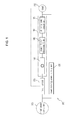
- FIG. 9 illustrates a driving power flow between the power supply 100 and the load 2 when the display apparatus 1 operates in the normal mode, according to an exemplary embodiment.
- the power supply 100 switches the current mode of the display apparatus 1 from the standby mode to the normal mode when an on signal is input through the remote controller 2.
- the power supply 100 turns the first switch 120 on.
- the second power converter 159b converts the rectified power to power at a predetermined level and outputs the converted power to the second controller 211 through the second standby power output port 159d.
- the second standby power output port 159d of the second power converter 159b is electrically connected to the second controller 211.
- the second controller 211 Upon supply of power through the second standby power output port 159d of the second power converter 159d, the second controller 211 checks the mode stored in the storage unit 213 and determines whether the mode is a deep sleep mode. When the mode is the deep sleep mode, the second controller 211 turns the fourth and fifth switches 159c and 170 on.
- the driving power converter 163 converts the power with the improved power factor to power at a predetermined level and supplies the converted power to the load 200. That is, the output port of the driving power converter 163 is connected to various loads.
- the second standby power unit 150b receives the AC power from the input power supply unit 110 when the first switch 120 is turned on, rectifies the AC power, converts the rectified power and supplies the converted power to loads as driving power.
- the second controller 211 when the second controller 211 inactivates the first receiver 157 in the normal mode, the second controller 211 can transmit a command for switching to the standby mode to the first controller 158.
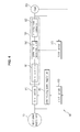
- FIG. 10 shows a driving power flow between the power supply 100 and the load 200 when the display apparatus 1 operates in the deep sleep mode, according to an exemplary embodiment.
- the power supply 100 switches the mode of the display apparatus 1 from the normal mode to the standby mode.
- the power supply 100 checks the mode stored in the storage unit 213.
- the power supply 100 controls the standby mode of the display apparatus 1 to switch to the deep sleep mode.
- the power supply 100 turns the first switch 120 off.
- the AC power of the input power supply unit 110 is applied to the second rectifier 152, rectified by the second rectifier 152, and then output to the first power converter 153.
- the power output to the first power converter 153 is converted to power for charging and then output to the charging unit 155.
- the second switch 154 When the charging unit 155 has been fully charged, the second switch 154 is turned off. When the charging unit 155 is discharged, the second switch 154 is turned on such that the power converted by the first power converter 153 is applied to the charging unit 155.
- the first standby power unit 150a performs charging and discharging of the charging unit 155 to provide standby power to the first controller 158 and the first receiver 157.
- the first controller 158 controls charging of the charging unit 155 on the basis of the voltage of the charging unit 155.
- the power supply 100 compares a voltage detected from the charging unit 155 with a reference voltage and maintains the second switch 154 in an off state when the detected voltage is higher than the reference voltage. If the detected voltage is lower than the reference voltage, the power supply 100 turns the second switch 154 on such that the charging unit 155 performs a charging operation. The power supply 100 re-detects the voltage of the charging unit 155 while the charging unit 155 performs a charging operation, compares the re-detected voltage with a full-charge voltage, and turns the second switch 154 off to stop charging when the re-detected voltage is higher than the full-charge voltage.
- the power of the charging unit 155 increases when the second switch 154 is turned on and is discharged with the lapse of time.
- the charging unit 155 supplies an average of 4 mW as standby power of the first controller 158 and the first receiver 157 and performs charging when the power of the charging unit 155 is maintained as a minimum of 2 mW for a predetermined time.
- the first receiver 157 If the first receiver 157 receives a power on signal of the remote controller 2 in the deep sleep mode, the first receiver 157 transmits the power on signal to the second controller 211.
- the first controller 158 turns the first switch 120 on such that the AC power of the input power supply unit 110 is applied to the second and third rectifiers 150 and 170, and then turns the third and fourth switches 160 and 165 on such that the power converted by the second power converter 159b and the driving power converter 163 is output.
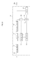
- FIG. 12 shows a driving power flow between the power supply 100 and the load 200 when the display apparatus 1 operates in the sleep mode, according to an exemplary embodiment.
- the power supply 100 turns the first switch 120 on in the sleep mode.
- the first standby power unit 150a performs charging and discharging of the charging unit 155 irrespective of turning on of the first switch 120 to supply driving power to the first controller 158 and the first receiver 157. However, the first receiver 157 is inactivated because the display apparatus 1 operates in the sleep mode.
- the on signal of the remote controller 2 for canceling the standby mode can be received through the second receiver 212.
- the first switch 120 is turned on such that the AC power of the input power supply unit 110 is applied to the first and third rectifiers 161 and 159a through the first switch 120.
- the third rectifier 159a rectifies the input AC power and outputs the rectified power to the second power converter 159b.
- the second power converter 159b converts the rectified power to power at a predetermined level and outputs the converted power to the second controller 211 through the second output port 159d.
- the second output port 159d of the second power converter 159b and the second controller 211 are electrically connected to each other.
- the second controller 211 checks the mode stored in the storage unit 213 and determines whether the checked mode is the deep sleep mode.
- the second controller 211 instructs the first controller 158 to maintain the inactivated state of the first receiver 157 and to maintain the on state of the first switch 120.
- the second controller 211 maintains the third and fourth switches 160 and 165 in an off state such that the power converted by the second and third power converters 155 and 180 is not output. That is, components included in an area 'B' do not operate.
- the second receiver 212 If the second receiver 212 receives a power on signal from the remote controller 2 in the sleep mode, the second receiver 212 transmits the power on signal to the second controller 211. In this case, the second controller 211 turns the fourth and fifth switches 159c and 170 on such that the power converted by the second power converter 159b and the driving power converter 163 is output.
- the process of outputting the power from the second power converter 159b and the driving power converter 153 according to turning on of the fourth and fifth switches 159c and 170 corresponds to that described with reference to FIG. 10 .
- FIG. 13 is a block diagram of a power supply 100 according to another exemplary embodiment.
- the power supply 100 includes the input power supply unit 110 (e.g., input power supplier), the first switch 120, the power-saving power supply unit 150 (e.g., power-saving power supplier), and the driving power supply unit 160 (e.g., driving power supplier).
- the input power supply unit 110 e.g., input power supplier
- the first switch 120 e.g., the first switch 120
- the power-saving power supply unit 150 e.g., power-saving power supplier
- the driving power supply unit 160 e.g., driving power supplier
- the power supply 100 performs the standby mode and the normal mode.
- the first controller 158 compares the voltage of the charging unit 155 with the first reference voltage, turns the second switch 154 on when the voltage of the charging unit 155 is lower than the first reference voltage, and turns the second switch 154 off when the voltage of the charging unit 155 is higher than the second reference voltage.
- the first receiver 157 waits to receive a power on/off signal from the remote controller 2 while receiving the power from the charging unit 155 to perform the deep sleep mode.
- the first standby power unit 150a generates standby power using power of the primary side before power conversion on the basis of the second power converter 159b and the driving power converter 163, whereas the second standby power unit 150b generates driving power using power of the secondary side after power conversion on the basis of the second power converter 159b and the driving power converter 163.
- a load 200 to which power is supplied from the power supply 100 according to an exemplary embodiment will now be briefly described.
- the second controller 211 receives the power converted by the second power converter 159b in the normal mode and controls the fourth and fifth switches 159c and 170 to supply the power converted by the second power converter 159b and the driving power converter 163 to the driver 230, the light source 220, the second controller 211 and the second receiver 212.
- the second controller 211 controls operations of the driver 230 and the light source 220 on the basis of a driving command transmitted from the second receiver 212 in the normal mode.
- the second controller 211 When power is re-supplied in the state that power is blocked, the second controller 211 switches the deep sleep mode to the normal mode. To achieve this, the second controller 211 turns the fourth and fifth switches 159c and 170 on. Accordingly, the power converted by the second power converter 159b and the driving power converter 163 is supplied to the driver 230 and the light source 220.
- the second controller 211 controls the sleep mode to be maintained if standby power is continuously applied through the second power converter 159b.
Landscapes
- Engineering & Computer Science (AREA)
- Power Engineering (AREA)
- Business, Economics & Management (AREA)
- Emergency Management (AREA)
- Charge And Discharge Circuits For Batteries Or The Like (AREA)
- Stand-By Power Supply Arrangements (AREA)
- Dc-Dc Converters (AREA)
Applications Claiming Priority (2)
| Application Number | Priority Date | Filing Date | Title |
|---|---|---|---|
| KR20110145609 | 2011-12-29 | ||
| KR1020120046888A KR101925142B1 (ko) | 2011-12-29 | 2012-05-03 | 파워 서플라이 및 그를 가지는 디스플레이 장치 |
Publications (3)
| Publication Number | Publication Date |
|---|---|
| EP2611016A2 true EP2611016A2 (de) | 2013-07-03 |
| EP2611016A3 EP2611016A3 (de) | 2015-09-02 |
| EP2611016B1 EP2611016B1 (de) | 2016-10-26 |
Family
ID=47754269
Family Applications (1)
| Application Number | Title | Priority Date | Filing Date |
|---|---|---|---|
| EP12199423.0A Not-in-force EP2611016B1 (de) | 2011-12-29 | 2012-12-27 | Stromversorgung und Anzeigevorrichtung damit |
Country Status (3)
| Country | Link |
|---|---|
| US (1) | US9444251B2 (de) |
| EP (1) | EP2611016B1 (de) |
| CN (1) | CN103187782B (de) |
Families Citing this family (15)
| Publication number | Priority date | Publication date | Assignee | Title |
|---|---|---|---|---|
| KR20130090122A (ko) * | 2012-02-03 | 2013-08-13 | 삼성전자주식회사 | 가전기기의 전원 장치 |
| JP5720660B2 (ja) * | 2012-11-29 | 2015-05-20 | コニカミノルタ株式会社 | 画像形成装置および二次電池の充電方法 |
| JP6110122B2 (ja) * | 2012-12-07 | 2017-04-05 | シナプティクス・ジャパン合同会社 | 集積回路装置、パネル表示装置及び表示パネルドライバ |
| US20150042175A1 (en) * | 2013-08-06 | 2015-02-12 | Yi Hsiang Chen | Power Supply Device For A Fixed Power Socket |
| CN103532226A (zh) * | 2013-10-09 | 2014-01-22 | 武汉百楚科技有限公司 | 基于超级电容器储能的电力操作电源 |
| KR102178635B1 (ko) * | 2013-12-16 | 2020-11-13 | 엘지전자 주식회사 | 영상표시기기 |
| KR102149952B1 (ko) * | 2014-04-17 | 2020-08-31 | 엘지전자 주식회사 | 가전기기 및 동작 방법 |
| WO2017137063A1 (de) * | 2016-02-08 | 2017-08-17 | Siemens Aktiengesellschaft | Konvertermodul für einen mehrstufenumrichter und verfahren zu dessen betrieb |
| KR102534244B1 (ko) | 2018-04-18 | 2023-05-19 | 삼성전자주식회사 | 복수의 소용량 파워 모듈들을 포함하는 디스플레이 장치 |
| KR102673597B1 (ko) | 2018-09-12 | 2024-06-12 | 삼성전자주식회사 | 디스플레이 시스템, 디스플레이 장치 및 그 제어 방법 |
| CN109410817B (zh) * | 2018-11-29 | 2022-06-03 | 昆山国显光电有限公司 | 供电控制装置和显示装置 |
| KR102646067B1 (ko) | 2019-07-17 | 2024-03-12 | 삼성전자주식회사 | 전자 장치, 그 제어 방법 및 디스플레이 장치 |
| KR20220008617A (ko) | 2020-07-14 | 2022-01-21 | 삼성전자주식회사 | 전원 공급 장치 및 이를 포함하는 전자 장치 |
| GB2611950A (en) * | 2020-08-14 | 2023-04-19 | Cirrus Logic Int Semiconductor Ltd | Wireless power architecture with series-coupled power converters |
| KR102934735B1 (ko) | 2021-04-21 | 2026-03-06 | 삼성전자주식회사 | 전자 장치 및 그 제어 방법 |
Family Cites Families (9)
| Publication number | Priority date | Publication date | Assignee | Title |
|---|---|---|---|---|
| EP1209793A1 (de) * | 2000-11-23 | 2002-05-29 | Semiconductor Components Industries LLC | Verfahren und Gerät zur Steuerung einer Stromversorgungseinrichtung |
| KR100576234B1 (ko) * | 2004-04-28 | 2006-05-03 | 삼성전자주식회사 | 전자장치 |
| KR20050112574A (ko) | 2004-05-27 | 2005-12-01 | 삼성에스디아이 주식회사 | 전원공급장치 및 이를 구비한 플라즈마 디스플레이 패널 |
| JP2008167629A (ja) | 2007-01-05 | 2008-07-17 | Funai Electric Co Ltd | 電源制御システム |
| GB0814409D0 (en) * | 2008-08-06 | 2008-09-10 | G24 Innovations Ltd | Electrical devices with standby mode |
| CN201422077Y (zh) * | 2009-06-09 | 2010-03-10 | 冠捷投资有限公司 | 一种电源供应器 |
| US8063512B2 (en) * | 2009-07-16 | 2011-11-22 | Chicony Power Technology Co., Ltd. | Power-saving power supply apparatus with battery module |
| KR100967438B1 (ko) | 2009-11-02 | 2010-07-01 | 코칩 주식회사 | 대기전력 저감장치 |
| KR20110080958A (ko) * | 2010-01-07 | 2011-07-13 | 삼성전자주식회사 | 비주얼 디스플레이 기기의 대기 전력을 공급하기 위한 대기전력 공급방법, 대기 전력 공급장치, 배터리 충전 방법 및 이를 적용한 비주얼 디스플레이 기기 |
-
2012
- 2012-12-27 EP EP12199423.0A patent/EP2611016B1/de not_active Not-in-force
- 2012-12-31 CN CN201210592833.2A patent/CN103187782B/zh not_active Expired - Fee Related
- 2012-12-31 US US13/731,258 patent/US9444251B2/en active Active
Non-Patent Citations (1)
| Title |
|---|
| None |
Also Published As
| Publication number | Publication date |
|---|---|
| US9444251B2 (en) | 2016-09-13 |
| CN103187782A (zh) | 2013-07-03 |
| EP2611016B1 (de) | 2016-10-26 |
| EP2611016A3 (de) | 2015-09-02 |
| CN103187782B (zh) | 2017-11-14 |
| US20130169612A1 (en) | 2013-07-04 |
Similar Documents
| Publication | Publication Date | Title |
|---|---|---|
| EP2611016B1 (de) | Stromversorgung und Anzeigevorrichtung damit | |
| KR101925142B1 (ko) | 파워 서플라이 및 그를 가지는 디스플레이 장치 | |
| KR100630933B1 (ko) | 외부전원의 공급 여부에 따라 디스플레이부로의 전원 공급경로가 변하는 전자장치 | |
| US10991297B2 (en) | Power supply device that outputs a signal corresponding to whether AC power is input, display device having same, and power supply method | |
| KR101411433B1 (ko) | 대기 전력 절감 회로 | |
| US20120201062A1 (en) | Standby power cut-off device and control method thereof and power supply | |
| US8421929B2 (en) | Display apparatus and power supplying method thereof | |
| US9876381B2 (en) | Bidirectional wireless charging device and bidirectional wireless charging system | |
| US20130155737A1 (en) | Switching mode power supply usable in an image forming apparatus, and image forming apparatus and method of supplying power by using the same | |
| KR20170120419A (ko) | 전원공급장치, 이를 구비한 디스플레이 장치 및 전원 공급 방법 | |
| US20140056033A1 (en) | Electronic apparatus and power controlling method thereof | |
| US9780667B2 (en) | Display apparatus, power supply and power supply method thereof | |
| US8754879B2 (en) | Display apparatus and power circuit devices thereof | |
| US10714978B2 (en) | Wireless power transmission apparatus that is turned off in standby state and electronic apparatus including wireless power transmission apparatus | |
| US8356196B2 (en) | Display apparatus and method for saving power thereof | |
| US20160036271A1 (en) | Display apparatus and power supplying method thereof | |
| US10644602B2 (en) | Adaptor, power supply system and power supply method thereof | |
| US9780668B2 (en) | Electronic apparatus, power supply and power control method thereof | |
| CN112020182B (zh) | 负载控制装置、负载控制方法以及非暂时性记录介质 | |
| KR20120070953A (ko) | 원격제어기기의 대기전력 절감 장치 및 방법 | |
| KR102663510B1 (ko) | 전자장치 및 그 제어방법 | |
| US20240380234A1 (en) | Charging/discharging apparatus, operation method thereof, and display apparatus including the charging/discharging apparatus | |
| US20240372398A1 (en) | Display apparatus and method of operating same | |
| KR20240164189A (ko) | 충방전 장치, 충방전 장치의 동작 방법, 및 충방전 장치를 포함하는 디스플레이 장치 | |
| KR100396598B1 (ko) | 원격 조정이 가능한 초절전 스탠바이 장치 |
Legal Events
| Date | Code | Title | Description |
|---|---|---|---|
| PUAI | Public reference made under article 153(3) epc to a published international application that has entered the european phase |
Free format text: ORIGINAL CODE: 0009012 |
|
| AK | Designated contracting states |
Kind code of ref document: A2 Designated state(s): AL AT BE BG CH CY CZ DE DK EE ES FI FR GB GR HR HU IE IS IT LI LT LU LV MC MK MT NL NO PL PT RO RS SE SI SK SM TR |
|
| AX | Request for extension of the european patent |
Extension state: BA ME |
|
| PUAL | Search report despatched |
Free format text: ORIGINAL CODE: 0009013 |
|
| AK | Designated contracting states |
Kind code of ref document: A3 Designated state(s): AL AT BE BG CH CY CZ DE DK EE ES FI FR GB GR HR HU IE IS IT LI LT LU LV MC MK MT NL NO PL PT RO RS SE SI SK SM TR |
|
| AX | Request for extension of the european patent |
Extension state: BA ME |
|
| RIC1 | Information provided on ipc code assigned before grant |
Ipc: H02J 9/00 20060101ALI20150727BHEP Ipc: H02M 1/42 20070101AFI20150727BHEP |
|
| 17P | Request for examination filed |
Effective date: 20160302 |
|
| RBV | Designated contracting states (corrected) |
Designated state(s): AL AT BE BG CH CY CZ DE DK EE ES FI FR GB GR HR HU IE IS IT LI LT LU LV MC MK MT NL NO PL PT RO RS SE SI SK SM TR |
|
| REG | Reference to a national code |
Ref country code: DE Ref legal event code: R079 Ref document number: 602012024540 Country of ref document: DE Free format text: PREVIOUS MAIN CLASS: H02M0001420000 Ipc: H02J0001000000 |
|
| GRAP | Despatch of communication of intention to grant a patent |
Free format text: ORIGINAL CODE: EPIDOSNIGR1 |
|
| RIC1 | Information provided on ipc code assigned before grant |
Ipc: H02J 1/00 20060101AFI20160427BHEP |
|
| INTG | Intention to grant announced |
Effective date: 20160531 |
|
| GRAS | Grant fee paid |
Free format text: ORIGINAL CODE: EPIDOSNIGR3 |
|
| GRAA | (expected) grant |
Free format text: ORIGINAL CODE: 0009210 |
|
| AK | Designated contracting states |
Kind code of ref document: B1 Designated state(s): AL AT BE BG CH CY CZ DE DK EE ES FI FR GB GR HR HU IE IS IT LI LT LU LV MC MK MT NL NO PL PT RO RS SE SI SK SM TR |
|
| REG | Reference to a national code |
Ref country code: GB Ref legal event code: FG4D |
|
| REG | Reference to a national code |
Ref country code: CH Ref legal event code: EP |
|
| REG | Reference to a national code |
Ref country code: AT Ref legal event code: REF Ref document number: 840643 Country of ref document: AT Kind code of ref document: T Effective date: 20161115 |
|
| REG | Reference to a national code |
Ref country code: IE Ref legal event code: FG4D |
|
| REG | Reference to a national code |
Ref country code: DE Ref legal event code: R096 Ref document number: 602012024540 Country of ref document: DE |
|
| REG | Reference to a national code |
Ref country code: LT Ref legal event code: MG4D |
|
| PG25 | Lapsed in a contracting state [announced via postgrant information from national office to epo] |
Ref country code: LV Free format text: LAPSE BECAUSE OF FAILURE TO SUBMIT A TRANSLATION OF THE DESCRIPTION OR TO PAY THE FEE WITHIN THE PRESCRIBED TIME-LIMIT Effective date: 20161026 |
|
| REG | Reference to a national code |
Ref country code: NL Ref legal event code: MP Effective date: 20161026 |
|
| REG | Reference to a national code |
Ref country code: AT Ref legal event code: MK05 Ref document number: 840643 Country of ref document: AT Kind code of ref document: T Effective date: 20161026 |
|
| PG25 | Lapsed in a contracting state [announced via postgrant information from national office to epo] |
Ref country code: NO Free format text: LAPSE BECAUSE OF FAILURE TO SUBMIT A TRANSLATION OF THE DESCRIPTION OR TO PAY THE FEE WITHIN THE PRESCRIBED TIME-LIMIT Effective date: 20170126 Ref country code: LT Free format text: LAPSE BECAUSE OF FAILURE TO SUBMIT A TRANSLATION OF THE DESCRIPTION OR TO PAY THE FEE WITHIN THE PRESCRIBED TIME-LIMIT Effective date: 20161026 Ref country code: GR Free format text: LAPSE BECAUSE OF FAILURE TO SUBMIT A TRANSLATION OF THE DESCRIPTION OR TO PAY THE FEE WITHIN THE PRESCRIBED TIME-LIMIT Effective date: 20170127 Ref country code: SE Free format text: LAPSE BECAUSE OF FAILURE TO SUBMIT A TRANSLATION OF THE DESCRIPTION OR TO PAY THE FEE WITHIN THE PRESCRIBED TIME-LIMIT Effective date: 20161026 |
|
| PG25 | Lapsed in a contracting state [announced via postgrant information from national office to epo] |
Ref country code: AT Free format text: LAPSE BECAUSE OF FAILURE TO SUBMIT A TRANSLATION OF THE DESCRIPTION OR TO PAY THE FEE WITHIN THE PRESCRIBED TIME-LIMIT Effective date: 20161026 Ref country code: IS Free format text: LAPSE BECAUSE OF FAILURE TO SUBMIT A TRANSLATION OF THE DESCRIPTION OR TO PAY THE FEE WITHIN THE PRESCRIBED TIME-LIMIT Effective date: 20170226 Ref country code: NL Free format text: LAPSE BECAUSE OF FAILURE TO SUBMIT A TRANSLATION OF THE DESCRIPTION OR TO PAY THE FEE WITHIN THE PRESCRIBED TIME-LIMIT Effective date: 20161026 Ref country code: FI Free format text: LAPSE BECAUSE OF FAILURE TO SUBMIT A TRANSLATION OF THE DESCRIPTION OR TO PAY THE FEE WITHIN THE PRESCRIBED TIME-LIMIT Effective date: 20161026 Ref country code: HR Free format text: LAPSE BECAUSE OF FAILURE TO SUBMIT A TRANSLATION OF THE DESCRIPTION OR TO PAY THE FEE WITHIN THE PRESCRIBED TIME-LIMIT Effective date: 20161026 Ref country code: RS Free format text: LAPSE BECAUSE OF FAILURE TO SUBMIT A TRANSLATION OF THE DESCRIPTION OR TO PAY THE FEE WITHIN THE PRESCRIBED TIME-LIMIT Effective date: 20161026 Ref country code: ES Free format text: LAPSE BECAUSE OF FAILURE TO SUBMIT A TRANSLATION OF THE DESCRIPTION OR TO PAY THE FEE WITHIN THE PRESCRIBED TIME-LIMIT Effective date: 20161026 Ref country code: PL Free format text: LAPSE BECAUSE OF FAILURE TO SUBMIT A TRANSLATION OF THE DESCRIPTION OR TO PAY THE FEE WITHIN THE PRESCRIBED TIME-LIMIT Effective date: 20161026 Ref country code: PT Free format text: LAPSE BECAUSE OF FAILURE TO SUBMIT A TRANSLATION OF THE DESCRIPTION OR TO PAY THE FEE WITHIN THE PRESCRIBED TIME-LIMIT Effective date: 20170227 Ref country code: BE Free format text: LAPSE BECAUSE OF FAILURE TO SUBMIT A TRANSLATION OF THE DESCRIPTION OR TO PAY THE FEE WITHIN THE PRESCRIBED TIME-LIMIT Effective date: 20161026 |
|
| REG | Reference to a national code |
Ref country code: DE Ref legal event code: R097 Ref document number: 602012024540 Country of ref document: DE |
|
| PG25 | Lapsed in a contracting state [announced via postgrant information from national office to epo] |
Ref country code: EE Free format text: LAPSE BECAUSE OF FAILURE TO SUBMIT A TRANSLATION OF THE DESCRIPTION OR TO PAY THE FEE WITHIN THE PRESCRIBED TIME-LIMIT Effective date: 20161026 Ref country code: CZ Free format text: LAPSE BECAUSE OF FAILURE TO SUBMIT A TRANSLATION OF THE DESCRIPTION OR TO PAY THE FEE WITHIN THE PRESCRIBED TIME-LIMIT Effective date: 20161026 Ref country code: SK Free format text: LAPSE BECAUSE OF FAILURE TO SUBMIT A TRANSLATION OF THE DESCRIPTION OR TO PAY THE FEE WITHIN THE PRESCRIBED TIME-LIMIT Effective date: 20161026 Ref country code: RO Free format text: LAPSE BECAUSE OF FAILURE TO SUBMIT A TRANSLATION OF THE DESCRIPTION OR TO PAY THE FEE WITHIN THE PRESCRIBED TIME-LIMIT Effective date: 20161026 Ref country code: DK Free format text: LAPSE BECAUSE OF FAILURE TO SUBMIT A TRANSLATION OF THE DESCRIPTION OR TO PAY THE FEE WITHIN THE PRESCRIBED TIME-LIMIT Effective date: 20161026 |
|
| REG | Reference to a national code |
Ref country code: CH Ref legal event code: PL |
|
| PG25 | Lapsed in a contracting state [announced via postgrant information from national office to epo] |
Ref country code: IT Free format text: LAPSE BECAUSE OF FAILURE TO SUBMIT A TRANSLATION OF THE DESCRIPTION OR TO PAY THE FEE WITHIN THE PRESCRIBED TIME-LIMIT Effective date: 20161026 Ref country code: BG Free format text: LAPSE BECAUSE OF FAILURE TO SUBMIT A TRANSLATION OF THE DESCRIPTION OR TO PAY THE FEE WITHIN THE PRESCRIBED TIME-LIMIT Effective date: 20170126 Ref country code: SM Free format text: LAPSE BECAUSE OF FAILURE TO SUBMIT A TRANSLATION OF THE DESCRIPTION OR TO PAY THE FEE WITHIN THE PRESCRIBED TIME-LIMIT Effective date: 20161026 |
|
| PLBE | No opposition filed within time limit |
Free format text: ORIGINAL CODE: 0009261 |
|
| STAA | Information on the status of an ep patent application or granted ep patent |
Free format text: STATUS: NO OPPOSITION FILED WITHIN TIME LIMIT |
|
| PG25 | Lapsed in a contracting state [announced via postgrant information from national office to epo] |
Ref country code: MC Free format text: LAPSE BECAUSE OF FAILURE TO SUBMIT A TRANSLATION OF THE DESCRIPTION OR TO PAY THE FEE WITHIN THE PRESCRIBED TIME-LIMIT Effective date: 20161026 |
|
| REG | Reference to a national code |
Ref country code: FR Ref legal event code: ST Effective date: 20170831 |
|
| 26N | No opposition filed |
Effective date: 20170727 |
|
| REG | Reference to a national code |
Ref country code: IE Ref legal event code: MM4A |
|
| PG25 | Lapsed in a contracting state [announced via postgrant information from national office to epo] |
Ref country code: FR Free format text: LAPSE BECAUSE OF NON-PAYMENT OF DUE FEES Effective date: 20170102 Ref country code: CH Free format text: LAPSE BECAUSE OF NON-PAYMENT OF DUE FEES Effective date: 20161231 Ref country code: LI Free format text: LAPSE BECAUSE OF NON-PAYMENT OF DUE FEES Effective date: 20161231 Ref country code: LU Free format text: LAPSE BECAUSE OF NON-PAYMENT OF DUE FEES Effective date: 20161227 |
|
| PG25 | Lapsed in a contracting state [announced via postgrant information from national office to epo] |
Ref country code: SI Free format text: LAPSE BECAUSE OF FAILURE TO SUBMIT A TRANSLATION OF THE DESCRIPTION OR TO PAY THE FEE WITHIN THE PRESCRIBED TIME-LIMIT Effective date: 20161026 Ref country code: IE Free format text: LAPSE BECAUSE OF NON-PAYMENT OF DUE FEES Effective date: 20161227 |
|
| PG25 | Lapsed in a contracting state [announced via postgrant information from national office to epo] |
Ref country code: HU Free format text: LAPSE BECAUSE OF FAILURE TO SUBMIT A TRANSLATION OF THE DESCRIPTION OR TO PAY THE FEE WITHIN THE PRESCRIBED TIME-LIMIT; INVALID AB INITIO Effective date: 20121227 Ref country code: CY Free format text: LAPSE BECAUSE OF FAILURE TO SUBMIT A TRANSLATION OF THE DESCRIPTION OR TO PAY THE FEE WITHIN THE PRESCRIBED TIME-LIMIT Effective date: 20161026 |
|
| PG25 | Lapsed in a contracting state [announced via postgrant information from national office to epo] |
Ref country code: MK Free format text: LAPSE BECAUSE OF FAILURE TO SUBMIT A TRANSLATION OF THE DESCRIPTION OR TO PAY THE FEE WITHIN THE PRESCRIBED TIME-LIMIT Effective date: 20161026 |
|
| PG25 | Lapsed in a contracting state [announced via postgrant information from national office to epo] |
Ref country code: MT Free format text: LAPSE BECAUSE OF NON-PAYMENT OF DUE FEES Effective date: 20161227 |
|
| PG25 | Lapsed in a contracting state [announced via postgrant information from national office to epo] |
Ref country code: TR Free format text: LAPSE BECAUSE OF FAILURE TO SUBMIT A TRANSLATION OF THE DESCRIPTION OR TO PAY THE FEE WITHIN THE PRESCRIBED TIME-LIMIT Effective date: 20161026 |
|
| PG25 | Lapsed in a contracting state [announced via postgrant information from national office to epo] |
Ref country code: AL Free format text: LAPSE BECAUSE OF FAILURE TO SUBMIT A TRANSLATION OF THE DESCRIPTION OR TO PAY THE FEE WITHIN THE PRESCRIBED TIME-LIMIT Effective date: 20161026 |
|
| PGFP | Annual fee paid to national office [announced via postgrant information from national office to epo] |
Ref country code: DE Payment date: 20201120 Year of fee payment: 9 Ref country code: GB Payment date: 20201125 Year of fee payment: 9 |
|
| REG | Reference to a national code |
Ref country code: DE Ref legal event code: R119 Ref document number: 602012024540 Country of ref document: DE |
|
| GBPC | Gb: european patent ceased through non-payment of renewal fee |
Effective date: 20211227 |
|
| PG25 | Lapsed in a contracting state [announced via postgrant information from national office to epo] |
Ref country code: GB Free format text: LAPSE BECAUSE OF NON-PAYMENT OF DUE FEES Effective date: 20211227 Ref country code: DE Free format text: LAPSE BECAUSE OF NON-PAYMENT OF DUE FEES Effective date: 20220701 |