EP2611075B1 - Procédé et système de détection d'incidents - Google Patents
Procédé et système de détection d'incidents Download PDFInfo
- Publication number
- EP2611075B1 EP2611075B1 EP11752861.2A EP11752861A EP2611075B1 EP 2611075 B1 EP2611075 B1 EP 2611075B1 EP 11752861 A EP11752861 A EP 11752861A EP 2611075 B1 EP2611075 B1 EP 2611075B1
- Authority
- EP
- European Patent Office
- Prior art keywords
- port
- destination
- packet
- source
- measurement point
- Prior art date
- Legal status (The legal status is an assumption and is not a legal conclusion. Google has not performed a legal analysis and makes no representation as to the accuracy of the status listed.)
- Not-in-force
Links
- 238000001514 detection method Methods 0.000 title claims description 62
- 230000004044 response Effects 0.000 claims description 87
- 238000005259 measurement Methods 0.000 claims description 83
- 238000000034 method Methods 0.000 claims description 35
- 239000012634 fragment Substances 0.000 claims description 7
- 238000004891 communication Methods 0.000 claims description 6
- 230000005540 biological transmission Effects 0.000 claims description 3
- 238000012545 processing Methods 0.000 description 8
- 239000003795 chemical substances by application Substances 0.000 description 7
- 238000010586 diagram Methods 0.000 description 6
- 230000008569 process Effects 0.000 description 6
- 230000006870 function Effects 0.000 description 5
- 238000005516 engineering process Methods 0.000 description 4
- 238000012986 modification Methods 0.000 description 3
- 230000004048 modification Effects 0.000 description 3
- 235000008694 Humulus lupulus Nutrition 0.000 description 2
- 230000009286 beneficial effect Effects 0.000 description 2
- 230000002457 bidirectional effect Effects 0.000 description 2
- 238000013461 design Methods 0.000 description 2
- 230000000694 effects Effects 0.000 description 2
- 230000008030 elimination Effects 0.000 description 2
- 238000003379 elimination reaction Methods 0.000 description 2
- 230000008439 repair process Effects 0.000 description 2
- 239000000523 sample Substances 0.000 description 2
- 101150081027 RNC1 gene Proteins 0.000 description 1
- 101100426111 Saccharomyces cerevisiae (strain ATCC 204508 / S288c) TRM2 gene Proteins 0.000 description 1
- 238000013459 approach Methods 0.000 description 1
- 238000013475 authorization Methods 0.000 description 1
- 239000000969 carrier Substances 0.000 description 1
- 230000000295 complement effect Effects 0.000 description 1
- 238000011161 development Methods 0.000 description 1
- 239000000284 extract Substances 0.000 description 1
- 238000000691 measurement method Methods 0.000 description 1
- 239000000203 mixture Substances 0.000 description 1
- 230000006855 networking Effects 0.000 description 1
- 238000011160 research Methods 0.000 description 1
- 238000012360 testing method Methods 0.000 description 1
Images

Classifications
-
- H—ELECTRICITY
- H04—ELECTRIC COMMUNICATION TECHNIQUE
- H04L—TRANSMISSION OF DIGITAL INFORMATION, e.g. TELEGRAPHIC COMMUNICATION
- H04L43/00—Arrangements for monitoring or testing data switching networks
- H04L43/08—Monitoring or testing based on specific metrics, e.g. QoS, energy consumption or environmental parameters
- H04L43/0823—Errors, e.g. transmission errors
-
- H—ELECTRICITY
- H04—ELECTRIC COMMUNICATION TECHNIQUE
- H04L—TRANSMISSION OF DIGITAL INFORMATION, e.g. TELEGRAPHIC COMMUNICATION
- H04L41/00—Arrangements for maintenance, administration or management of data switching networks, e.g. of packet switching networks
- H04L41/06—Management of faults, events, alarms or notifications
- H04L41/0677—Localisation of faults
-
- H—ELECTRICITY
- H04—ELECTRIC COMMUNICATION TECHNIQUE
- H04L—TRANSMISSION OF DIGITAL INFORMATION, e.g. TELEGRAPHIC COMMUNICATION
- H04L43/00—Arrangements for monitoring or testing data switching networks
- H04L43/10—Active monitoring, e.g. heartbeat, ping or trace-route
-
- H—ELECTRICITY
- H04—ELECTRIC COMMUNICATION TECHNIQUE
- H04L—TRANSMISSION OF DIGITAL INFORMATION, e.g. TELEGRAPHIC COMMUNICATION
- H04L45/00—Routing or path finding of packets in data switching networks
- H04L45/24—Multipath
-
- H—ELECTRICITY
- H04—ELECTRIC COMMUNICATION TECHNIQUE
- H04L—TRANSMISSION OF DIGITAL INFORMATION, e.g. TELEGRAPHIC COMMUNICATION
- H04L45/00—Routing or path finding of packets in data switching networks
- H04L45/28—Routing or path finding of packets in data switching networks using route fault recovery
Definitions
- the present invention relates to the field of network communications, and in particular, to a fault detection method and system in the field of network communications.
- Equal-cost multipath Equal-Cost MultiPath, ECMP greatly improves a resource utilization ratio of the IP network and balances a load of the IP network, but brings great difficulty to fault detection and location of the IP network.
- the ECMP can make multiple equal-cost paths share an IP packet load sent from a source end to a destination end, so as to achieve the purpose of making the most of resources of a bearer network.
- the so-called equal-cost paths means that among multiple paths that exist between the source end and the destination end, if some paths have equal path overheads, for example, the same number of hops, these paths are equal-cost paths.
- a router generally supports ECMP load sharing based on a 2-tuple (a source IP address and a destination IP address) and a 5-tuple (a source IP address, a destination IP address, a protocol number, a source port, and a destination port).
- a router groups packets passing through the router, where packets having the same 5-tuple are grouped together, and designates one path for packets of each group according to a load sharing algorithm. In this way, if protocol numbers, source port numbers, or destination port numbers of packets sent from a same source end to a same destination end are different from each other, the packets may pass through different paths.
- routing can be performed according to a port pair formed of a source port number and a destination port number, so as to distribute traffic from the same source end to the same destination end.
- a connectivity test may be performed by using a Ping command, so as to detect whether a network fault exists.
- the source end sends an ICMP (Internet Control Message Protocol, internet control message protocol) echo request packet (type 8) to the destination end.
- ICMP Internet Control Message Protocol, internet control message protocol
- the destination end receives the ICMP echo request packet
- the destination end returns an ICMP echo response packet (type 0)
- the source end can calculate round-trip time and a packet loss rate. If the source end does not receive the ICMP echo response packet within a certain time, the source end determines that the destination end is unreachable and the IP network is faulty.
- Ping packets sent through the Ping command have a same source IP address and a same destination IP address and a same protocol number 1, but do not have a port number, the Ping packets sent from the source end to the destination end can only pass through a same path, and connectivity of only one path can be tested through the Ping packets.
- the Ping packet cannot sense and therefore cannot determine existence of the fault of the another path.
- the Ping command cannot locate the fault.
- a network fault may also be detected by using a bidirectional forwarding detection (Bidirectional Forwarding Detection, BFD) packet.
- BFD Bidirectional Forwarding Detection
- the source end and the destination end periodically send to each other a BFD detection packet on a session channel established between the source end and the destination end.
- a protocol number of the BFD packet is 17, and a source port number and a destination port number of the BFD packet are both 3784. If the source end or the destination end does not receive a detection packet sent by the other party within a sufficiently long time, it is considered that the channel between the source end and the destination end is faulty.
- the BFD packet can pass through only one path, so that a fault of only one path can be detected, while faults of other equal-cost paths between the source end and the destination end cannot be detected. Meanwhile, a fault cannot be located by BFD either.
- a path between the source end and the destination end may also be determined by using a Traceroute (traceroute) command, so as to find whether an fault exists on the path and where the fault is located.
- Traceroute traceroute
- a TTL time to live
- ICMP timeout packet is used, which can implement fault detection and location.
- the source end sends an ICMP echo request packet to the destination end by progressively increasing the TTL field.
- a router receiving the ICMP echo request packet reduces the TTL by 1, and if the router finds that the TTL is 0, the router discards the packet, and returns an ICMP timeout packet (type 11) to the source end. In this way, an address of a certain router may be obtained.
- Traceroute packets sent from the source end to the destination end have a same source IP address, a same destination IP address, and a same protocol number (1), the packets have no source port number and no destination port number, so the Traceroute packets may also pass through only one path and a fault of only one path can be detected.
- port numbers are not distinguished in a fault detection process, sent packets can only pass through a same path, so a fault of only one path can be detected, and faults of other paths between the source end and the destination end cannot be detected.
- the network for example, the ECMP network
- path selection is based on ports, a fault between the source end and the destination end cannot be effectively detected.
- the basic idea is to perform ECMP-based load balancing by default. When a congestion occurs on a certain link, the solution dynamically reroute one or a few big flows to alternative paths to alleviate the congestion.
- the main contribution of our research is to design a scheme that enables per-flow reroute without introducing any modifications to IP switches and routers. All the flow-based operations and reroute functionalities are implemented in software that are installed on end hosts and centralized controllers. Tey call this scheme PROBE (Probe and RerOute based on ECMP).
- PROBE uses a traceroute-like approach to discover alternative paths and modifies packet headers to enable flow-based reroute.
- a traceroute-like approach to discover alternative paths and modifies packet headers to enable flow-based reroute.
- PROBE is a low cost, low complexity and feasible scheme that can be easily implemented in existing data center networks that consist of commodity switches and routers.
- US 2002/120730 A1 discloses a method for transmitting trap messages from an Agent system to a Manager system.
- the Manager System ensures that no trap messages are lost by checking that a sequence number of each received trap message from a particular Agent System is one higher than a sequence number of a previously received trap message. If a missing sequence number is detected, the Manager requests re-transmittal of the message associated with that sequence number.
- the Agent System can only send a given number, N of messages, before it is re-authorized to send more messages.
- the authorization is in the form of an acknowledgment message.
- Trap messages representing alarm conditions are particularly important. Alarm conditions are saved as long as the alarm is active. In case of an interruption of communications between the Agent and the Manager, all trap messages associated with these saved active alarm conditions are transmitted to the Manager System.
- these arrangements provide reliable communications between the Agent and Manager Systems, especially for the important messages representing alarm conditions in the Agent.
- Embodiments of the present invention provide a fault detection method and system, which can effectively detect a network fault between a source end and a destination end, so that multiple paths which each corresponds to a port pair formed of a source port number and a destination port number and is between the source end and the destination end can be effectively detected, thereby conveniently determining existence of the network fault.
- an embodiment of the present invention provides a fault detection method, including: sending (S110), by a source end, port scan packets based on at least two port pairs to a destination end, where each port pair includes a source port number and a destination port number and corresponds to a path between the source end and the destination end, wherein the sending the port scan packets based on the at least two port pairs to the destination end comprises:
- an embodiment of the present invention provides a system for fault detection.
- the system includes a source measurement point and a destination measurement point.
- the source measurement point includes: a first sending module (520), configured to send port scan packets based on at least two port pairs to the destination measurement point, where each port pair includes a source port number and a destination port number and corresponds to a path between the source measurement point and the destination measurement point; a first receiving module (525), configured to receive a response packet sent by the destination measurement point, where the response packet carries an unreceived port pair that is determined by the destination measurement point based on the port scan packets, wherein the unreceived port pair is a port pair having a destination port which does not receive a port scan packet; and a first determination module (530), configured to, based on the port pair carried in the response packet, determine a faulty path which corresponds to the unreceived port pair.
- a first sending module 520
- each port pair includes a source port number and a destination port number
- the destination measurement point includes: a second receiving module (565), configured to receive the port scan packets from the source measurement point; a second determination module (570), configured to,based on the port scan packets, determine a port pair which the destination port of does not receive a port scan packet; and a second sending module (575), configured to send, to the source measurement point, a response packet carrying the determined port pair; wherein the first sending module (520) comprises:
- the source end may send, based on at least two port pairs, port scan packets for detecting a path fault, so that the port scan packets can reach the destination end through the multiple paths, and the destination end determines, according to the port pairs carried in the received port scan packets, a port pair which does not receive a port scan packet, so as to determine that a path corresponding to the port pair which does not receive a port scan packet is faulty.
- the port scan packets can pass through paths corresponding to different port pairs, so that the multiple paths between the source end and the destination end may be detected.
- the present invention can implement more efficient fault detection and accurately find the existence of a fault in the network.
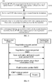
- a fault detection method 100 according to an embodiment of the present invention is described in combination with FIG. 1 .
- the method 100 includes: in S110, sending port scan packets based on at least two port pairs to a destination end, where each port pair includes a source port number and a destination port number and corresponds to a path between a source end and the destination end; in S120, receiving a response packet sent by the destination end, where the response packet carries a port pair which does not receive a port scan packet and is determined by the destination end based on the port scan packets; and in S130, based on the port pair carried by the response packet, determining a faulty path.
- Each path may correspond to a port pair formed of a source port number and a destination port number.
- a forwarding node for example, a router
- the source end may route and forward an IP packet based on a source port number and a destination port number that are carried in the IP packet.
- the source end scans port pairs and generates a port scan packet based on each of the multiple scanned port pairs, so that the port scan packet can be sent to the destination end through a path corresponding to a port pair carried in the port scan packet.
- the destination end continuously receives port scan packets from the source end, determines which port pair or port pairs fail to receive a port scan packet, and returns a port pair, which does not receive a port scan packet, as fault information to the source end.
- the source end determines, based on the returned fault information, that a path corresponding to the returned port pair is faulty, so as to detect a fault existing in the network.
- the source end sends, based on multiple port pairs, port scan packets for detecting a path fault, so that the port scan packets can reach the destination end through paths corresponding to different port pairs, and the destination end determines, according to the port pairs carried in the received port scan packets, a port pair which does not receive a port scan packet, so as to determine that a path corresponding to the port pair which does not receive a port scan packet is faulty.
- the port scan packets can pass through paths corresponding to different port pairs, so that the multiple paths between the source end and the destination end can be detected.
- the present invention can implement more efficient fault detection and accurately find existence of a fault in the network.
- an IP packet sent from the source end to the destination end have a same source IP address and a same destination IP address, so a path of the IP packet is related to a port pair formed of a source port number and a destination port number. Even if routing is also related to a protocol number, if the protocol number is fixed, the path of the IP packet is only related to the port pair. In this way, each port pair may correspond to one path between the source end and the destination end, and paths corresponding to multiple port pairs may be the same.
- a fault of a path between the source end and the destination end can be detected through a port scan packet sent based on a port pair.
- the port scan packet carries the port pair, so the port scan packet can pass through a path corresponding to the carried port pair, thereby performing fault detection on the path. If the port pair carried in the port scan packet is changed, multiple paths in a network, where routing is, for example, based on a 5-tuple, can be covered. If the destination end can receive a port scan packet, it indicates that a path through which the port scan packet passes is not faulty; otherwise, it indicates that a path corresponding to a port pair carried in the port scan packet is faulty.
- the source end can sequentially traverse the at least two port pairs, and based on a currently traversed port pair, send a port scan packet based on the port pair to the destination end.
- the source end may send a port scan packet corresponding to a currently scanned port pair. Therefore, port scan packets sent by the source end may pass through the multiple paths between the source end and the destination end, so that the multiple paths between the source end and the destination end are covered.
- a source port number and a destination port number in each port pair may be equal to each other.
- a source end and a destination end that communicate with each other using a same port number, so that a source port number and a destination port number in an IP packet are the same. Therefore, a path between the source end and the destination end may be represented by the source port number and the destination port number that are equal to each other.
- a source port number and a destination port number that are used for fault detection may also be the same, so that although a path through which a port scan packet for fault detection passes is different from the path through which the IP packet carrying service information passes, paths between the source end and the destination end may also be covered with port scan packets by traversing port pairs.
- port numbers ranging from 0 to 65535 are scanned in sequence each time of scanning. For example, first, a port scan packet with a source port number and a destination port number being both 0 is sent, then a port scan packet with a source port number and a destination port number being both 1 is sent, and then a port scan packet with a source port number and a destination port number being both 2 is sent. The rest can be done in the same manner, until a response message is received from the destination end.
- the source end may first fix a source port number and scan destination port numbers, and then increase the source port number by 1 and scan the destination port numbers.
- the rest can be done in the same manner. For example, the source end first fixes the source port number at 0, sets the destination port numbers to 0 to 65535, and sends corresponding port scan packets; then, sets the source port number to 1, sets the destination port numbers to 0 to 65535, and sends corresponding port scan packets.
- the rest can be done in the same manner. In this way, no matter whether the source port number and the destination port number are the same, multiple port pairs can be used to perform fault detection on multiple paths in the network.
- the port scan packet may be identified by a DF (Don't Fragment, don't fragment) flag bit, an MF (More Fragments, more fragments) flag bit, and an offset field in an IP header.
- DF Don't Fragment, don't fragment
- MF Me Fragments, more fragments
- the fields in the IP header of the port scan packet may be re-defined, so that the destination end can recognize the port scan packet.
- the destination end directly discards the port scan packet after processing the port scan packet, and does not submit the port scan packet to a service processing module. In this way, fault detection does not affect normal service processing.
- a current packet may be represented as a port scan packet by filling the DF flag bit, the MF flag bit, and the offset field in the IP header with specific fields.
- a form for filling the DF flag bit, the MF flag bit, and the offset field need to be different from that in existing common usage.
- the MF flag bit and the offset field are both 0; when the DF flag bit is 1, the MF flag bit may be 1, and in this case, the offset field may be any value; when the DF flag bit is 0, the MF flag bit may also be 0, and in this case, the offset field is 0.
- a value of the DF flag bit may be set to 1, a value of the MF flag bit may be set to 0, and a value of the offset field may not be set to all 0.
- the DF flag bit with the value 1 may be used to indicate that fragmenting is not performed; the MF flag bit with the value 0 may be used to indicate that no more fragment exists; and the offset field with a value being not all 0 may be used to indicate, in combination with the DF flag bit and the MF flag bit, that the packet is a port scan packet.
- the offset field is 1010101010101
- the DF flag bit, the MF flag bit, and the offset field in the IP header are re-defined as identifiers of the port scan packet, which neither conflicts with the current use nor causes exception in current data processing, and can greatly improve efficiency of recognizing the port scan packet.
- the port scan packet can be recognized through the IP header, so deep packet analysis does not need to be performed on the port scan packet, and a normal service is not affected.
- the source end sequentially scans the port pairs and sends corresponding port scan packets to the destination end, so that if the destination end does not receive a port scan packet corresponding to a certain port pair, it indicates that a path through which the port scan packet passes is faulty, so the destination end carries a port pair which does not receive a port scan packet as fault information in a response packet and returns the response packet to the source end.
- the response packet may be an ICMP packet, may also be a UDP (user Datagram Protocol, user datagram protocol) datagram, and definitely, may also be an IP packet in another form.
- the source end extracts, from the response packet, the port pair returned as the fault information, and determines that a path corresponding to the port pair is faulty, thereby completing network fault detection.
- the port scan packet sent in S110 is a UDP datagram
- the port scan packet may also be a TCP (Transmission Control Protocol, transmission control protocol) datagram, and in this case, a protocol number carried in the port scan packet is 6.
- TCP Transmission Control Protocol, transmission control protocol
- the UDP datagram or the TCP datagram is used as the port scan packet, so that during port scanning, port scan packets based on different port pairs can pass through different paths.
- the destination end receives the port scan packet sent by the source end, if it is found that a port scan packet corresponding to a certain port pair is not received, returns port scan fault information to the source end, and carries the port pair in a response packet and sends the response packet to the source end. For example, if the destination end receives a port scan packet with a source port number and a destination port number being both 98, and receives a port scan packet with a source port number and a destination port number being both 100, but does not receive a port scan packet with a source port number and a destination port number being both 99, the destination end returns a port pair with the source port number and the destination port number being both 99 as scan fault information to the source end.
- the response packet carrying the fault information may be an ICMP packet in a Ping manner, may also be a UDP datagram, and definitely, may also be an IP packet in another form, as long as the source end can be notified.
- the source end can know, according to the port pair carried in the received response packet, that the destination end does not receive the port scan packet corresponding to the port pair, so as to determine that the path through which the port scan packet passes is faulty.
- the source end sequentially traverses the port pairs, so that the port scan packets can reach the destination end through the multiple paths and the port scan packets can pass through the paths corresponding to the different port pairs, so as to implement detection on the multiple paths between the source end and the destination end.
- the present invention can implement more efficient fault detection and accurately find existence of a fault in a network.
- the port scan packet can be conveniently identified, which does not conflict with the current use but greatly improves efficiency of recognizing the port scan packet. Deep packet analysis does not need to be performed on the port scan packet, and a normal service is not affected.
- S210, S220, and S230 of the method 200 are basically the same as S110, S120, and S130 of the method 100.
- the method 200 may also include S202 and S204.
- S202 send, to a destination end, a negotiation request packet for determining whether the destination end supports a port scan packet.
- a source end cannot determine whether the destination end supports the method, that is, the source end cannot determine whether the destination end supports the port scan packet. If the destination end supports the port scan packet, the destination end can recognize the port scan packet, knows that the port scan packet is used for network fault detection and a port pair carried in the port scan packet indicates that a path corresponding to the port pair is not faulty, and returns fault information to the source end in a case of not receiving a certain port pair.
- the source end cannot determine whether the destination end supports the port scan packet, so the source end may send the negotiation request packet to the destination end to determine whether the destination end supports the port scan packet, so as to prevent fault detection according to the embodiment of the present invention from being performed meaninglessly in a case that the destination end does not support the port scan packet, and avoid a processing burden to the destination end that does not support the port scan packet, thereby avoiding an effect on processing performance of the destination end.
- the negotiation response packet is returned to the source end; otherwise, the destination end does not respond to the negotiation request packet, or responses in a form of not supporting the port scan packet.
- a source end can use a method 300 shown in FIG. 3 to determine whether a destination end supports a port scan packet.
- the option field that is, a data field
- the option field may be filled with a first identifier A, where A may be a special character string.
- the ICMP echo request packet with the option field carrying A is sent to the destination end.
- the destination end In response to the ICMP echo request packet, the destination end returns the ICMP echo response packet.
- the source end fills the option field of the ICMP echo request packet with the first identifier to assist in determining whether the destination end supports the port scan packet.
- the destination end may fill the ICMP echo response packet with a second identifier B different from the first identifier A and return the ICMP echo response packet to the source end.
- the second identifier B may also be a special character string, as long as it is different from the first identifier A.
- the destination end does not know the meaning of the first identifier A.
- the destination end does not modify the first identifier A. That is to say, if the destination end does not support the port scan packet, the ICMP echo response packet returned by the destination end still carries the first identifier A in the option field.
- the ICMP echo response packet is a negotiation response packet indicating that the destination end supports the port scan packet.
- an existing ICMP echo request packet and ICMP echo response packet may be used, only the option field is filled with an identifier at the same time when a Ping operation is performed, so as to conveniently determine whether the destination end supports the port scan packet.
- the implementation is simple.
- the method 200 may further include S232 and S234.
- the port pair carried in the response packet indicates that a path corresponding to the port pair is faulty, so the source end can further locate a fault of the faulty path, so as to determine which network segment or which router is faulty.
- the source end may adopt a manner of a Traceroute operation.
- a source port number and a destination port number that are the same as those in a port scan packet may be used, so that the fault location packet and the port scan packet pass through the same path.
- the fault location packet needs to use a same protocol number as that of the port scan packet. However, as long as the protocol number is fixed, the fault location packet and the port scan packet can pass through the same path when carrying the same port number. Therefore, in a case that the source port number and the destination port number corresponding to the faulty path are determined, the fault location packet carries the faulty port pair, and then the fault in the faulty path can be located through the Traceroute operation.
- the fault location packet for fault location is also a UDP datagram with a protocol number 17.
- the fault location packet is also a TCP datagram with a protocol number 6.
- the port scan packet and the fault location packet have a same 5-tuple and pass through the same path, so that the fault location packet passes through the faulty path, thereby completing the fault location.
- the Traceroute operation is completed through the UDP datagram or the TCP datagram.
- the UDP datagram or the TCP datagram carries port pair information returned by the destination end through the response packet, so that the UDP datagram or the TCP datagram passes through the faulty path.
- a manner for locating a fault by modifying a TTL field is basically the same as a relevant technology.
- a specific process is as follows:
- the source end sends a UDP datagram with a TTL field being 2 to the destination end, where a 5-tuple in the UDP datagram is the same as that described above.
- the first router reduces the TTL by 1, finds the TTL is not 0, and forwards the UDP datagram to a second router.
- the second router reduces the TTL value by 1, finds the TTL is equal to 0, discards the UDP datagram, and returns an ICMP timeout packet. In this way, an IP address of the second router in the path is obtained.
- a router that does not return an ICMP timeout packet is a fault point. It can be determined, through the fault point, that the router is faulty or a network segment between the router and a previous-hop router is faulty.
- the fault detection method before fault detection, it is determined whether the destination end supports the port scan packet, so as to prevent the port scan packet from being sent blindly and an unnecessary processing burden from being brought to a destination end that does not support the port scan packet, so that the fault detection method can be effectively executed.
- the fault location packet such as the UDP datagram and the TCP datagram is used to locate the fault based on the Traceroute operation, so as to determine a specific position of the fault more accurately, which is beneficial to fault elimination and repair.
- IP-based telecommunication With the advance of IP-based telecommunication, more and more operators gradually move voice services to an IP network.
- a path through which a voice data packet passes for example, base station 1-RNC1-UMG1-RNC2 -base station 2, is borne on an IP bearer network.
- Most of the IP bearer networks start load sharing based on a 5-tuple. Voice services of different users may be in different bearer paths. When a fault occurs, it is difficult to detect and locate the fault.
- FIG. 4 is a schematic diagram of fault detection between an RNC and a UMG, where the RNC is a source end and the UMG is a destination end.
- the RNC sends a negotiation request packet to the UMG, where the negotiation request packet is an ICMP echo request packet, and an option field in the ICMP echo request packet is filled with a special character string A.
- the UMG returns a negotiation response packet to the RNC, so as to indicate that the UMG also supports the fault detection method according to the embodiment of the present invention.
- the negotiation response packet is an ICMP echo response packet, and an option field in the ICMP echo response packet is filled with a special character string B.
- the RNC sequentially scans port pairs, and based on a currently scanned port pair, sends a port scan packet carrying the port pair.
- a call of a pair of users occupies a source port number and a destination port number that are the same, so during scanning, sequential traversal is performed in a manner that the source port number is equal to the destination port number.
- a source IP address is an IP address of the RNC
- a destination IP address is an IP address of the UMG
- a protocol number is 17, and the source port number is equal to the destination port number.
- Sequential traversal is performed from 0 to 65535. For each port number, three same port scan packets may be sent.
- the UMG finds that a port scan packet corresponding to a certain port pair is not received, the UMG sends a response packet to the RNC, so as to return port scan fault information. For example, if the UMG receives a port scan packet with a port number 100 but does not receive a port scan packet with a port number 99, the UMG returns, to the RNC, a response packet carrying the port number 99.
- the response packet may be an ICMP packet, and may also be a packet in another form.
- the RNC stops port scanning, locates a fault in a path corresponding to the faulty port (for example, the port number 99) according to the fault information acquired from the response packet, and sends a fault location packet to the UMG.
- a source IP address is the IP address of the RNC
- a destination IP address is the IP address of the UMG
- a protocol number is 17, and a source port number and a destination port number are both a faulty port number (for example, the port number 99) in a manner of a Traceroute operation
- the fault location packet is sent by modifying a TTL value.
- a router receiving the fault location packet on the faulty path reduces the TTL value by 1, and if the TTL is 0, returns a fault location response packet, that is, an ICMP timeout packet.
- Operations on the fault location packet and the fault location response packet are similar to the Traceroute operation. For details, reference may be made to S232 and S234 in the method 200 of FIG. 2 . Based on a router that does not return an ICMP timeout packet and is on the fault path, a fault can be located.
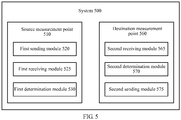
- a fault detection system 500 includes a source measurement point 510 and a destination measurement point 560.
- the source measurement point 510 and the destination measurement point 560 may be network elements in a network, and may also be functional modules located on a network element.
- a fault of multiple paths (for example, multiple equal-cost paths) between the source measurement point 510 and the destination measurement point 560 can be detected by executing the foregoing method between the source measurement point 510 and the destination measurement point 560.
- the source measurement point 510 includes a first sending module 520, a first receiving module 525, and a first determination module 530.
- the first sending module 520 may be configured to send port scan packets based on at least two port pairs to the destination measurement point 560, where each port pair includes a source port number and a destination port number and corresponds to a path between the source measurement point 510 and the destination measurement point 560.
- the first receiving module 525 may be configured to receive a response packet sent by the destination measurement point 560, where the response packet carries a port pair which does not receive a port scan packet and is determined by the destination measurement point 560 based on the port scan packets.
- the first determination module 530 may be configured to, based on the port pair carried in the response packet, determine a faulty path.
- the destination measurement point 560 includes a second receiving module 565, a second determination module 570, and a second sending module 575.
- the second receiving module 565 may be configured to receive the port scan packets from the source measurement point 510.
- the second determination module 570 may be configured to, based on the port scan packets, determine a port pair which does not receive a port scan packet.
- the second sending module 575 may be configured to send, to the source measurement point 510, the response packet carrying the determined port pair.
- the operation of the destination measurement point 560 corresponds to the operation of the source measurement point 510.
- the second receiving module 565 of the destination measurement point 560 receives the port scan packets sent by the first sending module 520 of the source measurement point 510.
- the second sending module 575 of the destination measurement point 560 sends the response packet to the first receiving module 525 of the source measurement point 510, where the port pair carried in the response packet is obtained by the second determination module 570 of the destination measurement point 560.
- the source measurement point sends, based on multiple port pairs, port scan packets for detecting a path fault, so that the port scan packets can reach the destination measurement point through multiple paths, and the destination measurement point can determine, according to the port pairs carried in the received port scan packets, a port pair which does not receive a port scan packet, so as to determine a faulty path based on the port pair which does not receive a port scan packet.
- the port scan packets can pass through paths corresponding to different port pairs, so as to implement detection of multiple paths between the source measurement point and the destination measurement point.
- the present invention can implement more efficient fault detection and accurately find existence of a fault in the network.
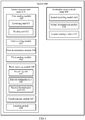
- FIG. 6 is a structural block diagram of a system for fault detection 600 according to an embodiment of the present invention.
- the system 600 includes a source measurement point 610 and a destination measurement point 660.
- a first sending module 620, a first receiving module 625 and a first determination module 630 in the source measurement point 610 are basically the same as the first sending module 520, the first receiving module 525, and the first determination module 530 in the source measurement point 510.
- a second receiving module 665, a second determination module 670 and a second sending module 675 in the destination measurement point 660 are basically the same as the second receiving module 565, the second determination module 570, and the second sending module 575 in the destination measurement point 510.
- the first sending module 620 in the source measurement point 610 may include a traversing unit 621 and a sending unit 622.
- the traversing unit 621 may be configured to sequentially traverse at least two port pairs.
- the sending unit 622 may be configured to, based on a currently traversed port pair, send a port scan packet based on the port pair to the destination measurement point 660.
- the first sending module 620 may be configured to send port scan packets based on the at least two port pairs to the destination measurement point 660, where a source port number and a destination port number in each port pair are equal. In this way, during scanning based on the port pairs, sequential scanning is performed in a manner that the source port number is equal to the destination port number.
- the source measurement point 610 may also include a third sending module 635 and a third receiving module 640.
- the third sending module 635 may be configured to send, to the destination measurement point 660, a negotiation request packet for determining whether the destination measurement point 660 supports the port scan packet.
- the third receiving module 640 may be configured to receive a negotiation response packet that is sent by the destination measurement point 660 and used for indicating that the port scan packet is supported.
- the third receiving module 635 may be configured to send an ICMP echo request packet to the destination measurement point 660, where an option field of the ICMP echo request packet is filled with a first identifier.
- the third receiving module 640 may include a receiving unit 641, a first determination unit 642, and a second determination unit 643.
- the receiving unit 641 may be configured to receive an ICMP echo response packet returned from the destination measurement point 660.
- the first determination unit 642 may be configured to determine whether an option field of the ICMP echo response packet is filled with a second identifier different from the first identifier.
- the second determination unit 643 may be configured to, if it is determined that the option field is filled with the second identifier, determine that the ICMP echo response packet is the negotiation response packet.
- the port scan packet sent by the first sending module 620 may be identified by a DF flag bit, an MF flag bit, and an offset field in an IP header.
- the DF flag bit has a value of 1 and is used to indicate that fragmenting is not performed; the MF flag bit has a value of 0 and is used to indicate that no more fragment exists; and the offset field has a value being not all 0 and is used to indicate, in combination with the DF flag bit and the MF flag bit, that the packet is a port scan packet.
- the source measurement point 610 may also include a fourth sending module 645 and a location module 650.
- the fourth sending module 645 may be configured to send a fault location packet to the destination measurement point 660 based on the port pair carried in the response packet.
- the location module 650 may be configured to locate a fault in a path based on a TTL field of the fault location packet.
- the first sending module 620 For the foregoing operations and/or functions of the first sending module 620, the third sending module 535, the third receiving module 540, the receiving unit 641, the first determination unit 642, the second determination unit 643, the fourth sending module 645, and the location module 650, reference may be made to S110 in the method 100, S202, S204, S232, and S234 in the method 200, and S310 to S340 in the method 300.
- the source measurement point uses the third sending module and the third receiving module to determine, before the fault detection, whether the destination measurement point supports the port scan packet, so as to prevent the port scan packet from being sent blindly and an unnecessary processing burden from being brought to a destination end that does not support the port scan packet, so that a fault detection process can be effectively performed.
- an existing ICMP echo request packet and ICMP echo response packet are used to determine whether the destination measurement point supports the port scan packet, because only the option field is filled with an identifier at the same time when a Ping operation is performed, it is convenient to determine whether the destination measurement point supports the port scan packet, and the implementation is simple.
- the fault location packet such as a UDP datagram and a TCP datagram may be used to locate the fault based on a Traceroute operation after the fault detection, so as to determine a specific position of the fault more accurately, thereby being beneficial to fault elimination and repair.
- the method steps described in combination with the embodiments disclosed in this document may be implemented by hardware, a software program executed by a processor, or a combination of the two.
- the software program can be stored in a random access memory (RAM), a memory, a read-only memory (ROM), an electrically programmable ROM, an electrically erasable programmable ROM, a register, a hard disk, a removable magnetic disk, or a CD-ROM, or any other type of storage medium commonly known in the art.
Landscapes
- Engineering & Computer Science (AREA)
- Computer Networks & Wireless Communication (AREA)
- Signal Processing (AREA)
- Environmental & Geological Engineering (AREA)
- Health & Medical Sciences (AREA)
- Cardiology (AREA)
- General Health & Medical Sciences (AREA)
- Data Exchanges In Wide-Area Networks (AREA)
Claims (13)
- Procédé de détection de défaillance dans un réseau de communications de protocole Internet, IP, le procédé comprenant :l'envoi (S110), par une extrémité de source, de paquets de balayage de ports d'après au moins deux paires de ports à une extrémité de destination, dans lequel chaque paire de ports comprend un nombre de ports de source et un nombre de ports de destination et correspond à un trajet entre l'extrémité de source et l'extrémité de destination, dans lequel l'envoi des paquets de balayage de ports d'après les au moins deux paires de ports à l'extrémité de destination comprend :la traversée séquentielle des au moins deux paires de ports ; etd'après une paire de ports actuellement traversée, l'envoi d'un paquet de balayage de ports d'après la paire de ports à l'extrémité de destination, dans lequel le paquet de balayage de ports comporte la paire de ports de balayage actuelle ;la réception (S120), par l'extrémité de source d'un paquet de réponse envoyé par l'extrémité de destination, dans lequel le paquet de réponse porte une paire de ports non reçue qui est déterminée par l'extrémité de destination d'après les paquets de balayage de ports, dans lequel la paire de ports non reçue est une paire de ports ayant un port de destination qui ne reçoit pas de paquet de balayage de ports ; etla détermination (130), par l'extrémité de source, d'après la paire de ports non reçue portée dans le paquet de réponse, d'un trajet défaillant qui correspond à la paire de ports non reçue.
- Procédé selon la revendication 1, dans lequel l'envoi des paquets de balayage de ports d'après les au moins deux paires de ports à l'extrémité de destination comprend :l'envoi des paquets de balayage de ports d'après les au moins deux paires de ports à l'extrémité de destination, dans lequel le nombre de ports de source et le nombre de ports de destination dans chaque paire de ports sont égaux.
- Procédé selon la revendication 1, dans lequel avant l'envoi des paquets de balayage de ports d'après les au moins deux paires de ports à l'extrémité de destination, le procédé comprend en outre :l'envoi (S202), à l'extrémité de destination, d'un paquet de demande de négociation pour déterminer si l'extrémité de destination prend en charge les paquets de balayage de ports ; etla réception (S204) d'un paquet de réponse de négociation qui est envoyé par l'extrémité de destination et utilisé pour indiquer que les paquets de balayage de ports sont pris en charge.
- Procédé selon la revendication 3, dans lequel l'envoi, à l'extrémité de destination, du paquet de demande de négociation pour déterminer si l'extrémité de destination prend en charge les paquets de balayage de ports comprend
l'envoi (S310), d'un paquet de demande d'écho ICMP à l'extrémité de destination, dans lequel un champ d'option du paquet de demande d'écho ICMP est rempli avec un premier identifiant ; et
la réception du paquet de réponse de négociation qui est envoyé par l'extrémité de destination et utilisé pour indiquer que les paquets de balayage de ports sont pris en charge comprend :la réception (S320), d'un paquet de réponse d'écho ICMP renvoyé depuis l'extrémité de destination ;la détermination (S330), pour savoir si un champ d'option du paquet de réponse d'écho ICMP est rempli avec un second identifiant différent du premier identifiant ; ets'il est déterminé que le champ d'option est rempli avec le second identifiant, la détermination selon laquelle le paquet de réponse d'écho ICMP est le paquet de réponse de négociation. - Procédé selon la revendication 1, dans lequel l'envoi des paquets de balayage de ports d'après les au moins deux paires de ports à l'extrémité de destination comprend :l'envoi des paquets de balayage de ports d'après les au moins deux paires de ports à l'extrémité de destination, dans lequel chaque paquet de balayage de ports des paquets de balayage de ports est identifié par un bit de signalisation DF, un bit de signalisation MF, et un champ décalé dans un en-tête IP.
- Procédé selon la revendication 5, dans lequel chaque paquet de balayage de ports des paquets de balayage de ports est identifié par le bit de signalisation DF, le bit de signalisation MF, et le champ décalé dans l'en-tête IP comprend le fait que :le bit de signalisation DF a une valeur de 1 et est utilisé pour indiquer qu'une fragmentation n'est pas réalisée ;le bit de signalisation MF a une valeur de 0 et est utilisé pour indiquer qu'aucun autre fragment n'existe ; etle champ décalé a une valeur qui n'est pas entièrement 0 et est utilisé pour indiquer, en combinaison avec le bit de signalisation DF et le bit de signalisation MF, que le paquet est un paquet de balayage de ports.
- Procédé selon la revendication 1, comprenant en outre :d'après la paire de ports portée dans le paquet de réponse, l'envoi d'un paquet de localisation de défaillance à l'extrémité de destination ; etd'après un champ TTL du paquet de localisation de défaillance, la localisation d'une défaillance dans le trajet.
- Procédé selon la revendication 7, dans lequel les paquets de balayage de ports et le paquet de localisation de défaillance adoptent l'un d'un protocole de datagramme utilisateur et d'un protocole de contrôle de transmission.
- Système de détection de défaillance dans un réseau de communications de protocole Internet, IP, le système comprenant un point de mesure de source et un point de mesure de destination, dans lequel
le point de mesure de source comprend :un premier module d'envoi (520), configuré pour envoyer des paquets de balayage de ports d'après au moins deux paires de ports au point de mesure de destination, dans lequel chaque paire de ports comprend un nombre de ports de source et un nombre de ports de destination et correspond à un trajet entre le point de mesure de source et le point de mesure de destination ;un premier module de réception (525), configuré pour recevoir un paquet de réponse envoyé par le point de mesure de destination, dans lequel le paquet de réponse porte une paire de ports non reçue qui est déterminée par le point de mesure de destination d'après les paquets de balayage de ports, dans lequel la paire de ports non reçue est une paire de ports ayant un port de destination qui ne reçoit pas de paquet de balayage de ports ; etun premier module de détermination (530), configuré, d'après la paire de ports non reçue portée dans le paquet de réponse, pour déterminer un trajet défaillant qui correspond à la paire de ports non reçue ;le point de mesure de destination comprend :un deuxième module de réception (565), configuré pour recevoir les paquets de balayage de ports en provenance du point de mesure de source ;un second module de détermination (570), configuré pour déterminer, d'après les paquets de balayage de ports, la paire de ports non reçue, dans lequel la paire de ports non reçue est une paire de ports ayant un port de destination qui ne reçoit pas de paquet de balayage de ports ; etun deuxième module d'envoi (575), configuré pour envoyer, au point de mesure de source, le paquet de réponse portant la paire de ports déterminée ;dans lequel le premier module d'envoi (520) comprend :une unité de traversée (621), configurée pour traverser séquentiellement les au moins deux paires de ports ; etune unité d'envoi (622), configurée, d'après une paire de ports actuellement traversée, pour envoyer un paquet de balayage de ports d'après la paire de ports actuellement traversée au point de mesure de destination. - Système selon la revendication 9, dans lequel le premier module d'envoi (520) est configuré pour envoyer les paquets de balayage de ports d'après les au moins deux paires de ports au point de mesure de destination, et le nombre de ports de source et le nombre de ports de destination dans chaque paire de ports sont égaux.
- Système selon la revendication 9, dans lequel le point de mesure de source comprend en outre :un troisième module d'envoi (635), configuré pour envoyer, au point de mesure de destination, un paquet de demande de négociation pour déterminer si le point de mesure de destination prend en charge les paquets de balayage de ports ; etun troisième module de réception (625), configuré pour recevoir un paquet de réponse de négociation qui est envoyé par le point de mesure de destination et utilisé pour indiquer que les paquets de balayage de ports sont pris en charge.
- Système selon la revendication 11, dans lequel le troisième module de réception (625) est configuré pour envoyer un paquet de demande d'écho ICMP au point de mesure de destination, et un champ d'option du paquet de demande d'écho ICMP est rempli avec un premier identifiant ;
dans lequel le troisième module de réception (640) comprend :une unité de réception (641), configurée pour recevoir un paquet de réponse d'écho ICMP renvoyé depuis le point de mesure de destination ;une première unité de détermination (642), configurée pour déterminer si un champ d'option du paquet de réponse d'écho ICMP est rempli avec un second identifiant différent du premier identifiant ; etune seconde unité de détermination (643), configurée, s'il est déterminé que le champ d'option est rempli avec le second identifiant, pour déterminer que le paquet de réponse d'écho ICMP est le paquet de réponse de négociation. - Système selon la revendication 9, dans lequel le point de mesure de source comprend en outre :un quatrième module d'envoi (645), configuré pour envoyer un paquet de localisation de défaillance au point de mesure de destination d'après la paire de ports portée dans le paquet de réponse ; etun module de localisation (650), configuré pour localiser une défaillance dans le trajet d'après un champ TTL du paquet de localisation de défaillance.
Applications Claiming Priority (1)
| Application Number | Priority Date | Filing Date | Title |
|---|---|---|---|
| PCT/CN2011/073144 WO2011110118A2 (fr) | 2011-04-21 | 2011-04-21 | Procédé et système de détection d'incidents |
Publications (3)
| Publication Number | Publication Date |
|---|---|
| EP2611075A2 EP2611075A2 (fr) | 2013-07-03 |
| EP2611075A4 EP2611075A4 (fr) | 2013-07-17 |
| EP2611075B1 true EP2611075B1 (fr) | 2018-01-24 |
Family
ID=44519900
Family Applications (1)
| Application Number | Title | Priority Date | Filing Date |
|---|---|---|---|
| EP11752861.2A Not-in-force EP2611075B1 (fr) | 2011-04-21 | 2011-04-21 | Procédé et système de détection d'incidents |
Country Status (4)
| Country | Link |
|---|---|
| US (1) | US9203716B2 (fr) |
| EP (1) | EP2611075B1 (fr) |
| CN (1) | CN102177681B (fr) |
| WO (1) | WO2011110118A2 (fr) |
Families Citing this family (34)
| Publication number | Priority date | Publication date | Assignee | Title |
|---|---|---|---|---|
| CN103166786B (zh) * | 2011-12-15 | 2019-03-08 | 中兴通讯股份有限公司 | 一种实现链路跟踪的方法和系统 |
| JP5842641B2 (ja) * | 2012-01-31 | 2016-01-13 | 富士通株式会社 | 通信システム、および生成装置 |
| US9239749B2 (en) * | 2012-05-04 | 2016-01-19 | Paraccel Llc | Network fault detection and reconfiguration |
| US9311022B2 (en) * | 2013-10-07 | 2016-04-12 | Dell Products L.P. | System and method for improved communication in a storage network |
| CN104053176B (zh) * | 2014-06-26 | 2017-10-17 | 国家计算机网络与信息安全管理中心 | 一种基于traceroute的运营商核心节点识别方法 |
| CN105634857A (zh) * | 2014-11-26 | 2016-06-01 | 中兴通讯股份有限公司 | 链路连通性检测方法及装置 |
| CN106330597B (zh) * | 2015-07-10 | 2019-07-26 | 新华三技术有限公司 | Vxlan隧道端点vtep之间的路径可达检测方法和装置 |
| CN106559325B (zh) * | 2015-09-25 | 2020-06-09 | 华为技术有限公司 | 路径检测方法和装置 |
| US9813911B2 (en) * | 2015-12-08 | 2017-11-07 | Panasonic Avionics Corporation | Methods and systems for monitoring computing devices on a vehicle |
| CN105939212B (zh) * | 2016-02-25 | 2019-05-07 | 杭州迪普科技股份有限公司 | 状态探测的方法及装置 |
| CN107171882B (zh) * | 2016-03-08 | 2021-02-09 | 华为技术有限公司 | 检测等价多路径路由功能的方法、设备和系统 |
| CN105847460B (zh) * | 2016-03-15 | 2018-12-28 | 迈普通信技术股份有限公司 | 一种实现双向转发检测的方法及设备 |
| CN107426042A (zh) * | 2016-05-23 | 2017-12-01 | 中兴通讯股份有限公司 | 一种报文传输方法和发送设备 |
| US10298491B2 (en) * | 2016-08-25 | 2019-05-21 | Cisco Technology, Inc. | Efficient path detection and validation between endpoints in large datacenters |
| CN106130800B (zh) * | 2016-08-29 | 2020-01-03 | 杭州迪普科技股份有限公司 | 一种数据帧的处理方法及装置 |
| CN107948989B (zh) * | 2016-10-13 | 2021-02-12 | 北京国双科技有限公司 | 一种移动终端联网时长的计算方法及装置 |
| CN107342908B (zh) * | 2016-11-30 | 2021-02-19 | 新华三技术有限公司 | 一种发送双向转发检测报文的方法和装置 |
| US10320954B2 (en) | 2017-02-03 | 2019-06-11 | Microsoft Technology Licensing, Llc | Diffusing packets to identify faulty network apparatuses in multipath inter-data center networks |
| US20180278514A1 (en) * | 2017-03-27 | 2018-09-27 | Juniper Networks, Inc. | Traceroute for multi-path routing |
| CN108737206B (zh) * | 2017-04-24 | 2021-11-12 | 中兴通讯股份有限公司 | 网络通道的选路方法、装置及其计算机设备 |
| CN108776625A (zh) * | 2018-06-26 | 2018-11-09 | 郑州云海信息技术有限公司 | 一种服务故障的修复方法、装置和存储介质 |
| CN111245666B (zh) * | 2018-11-29 | 2022-12-06 | 华为技术有限公司 | 数据传输方法、装置及系统 |
| CN110290067A (zh) * | 2019-07-01 | 2019-09-27 | 北京云端智度科技有限公司 | 一种基于多次协议测试的端到端网络路径的发现方法 |
| CN112787881A (zh) * | 2019-11-11 | 2021-05-11 | 中兴通讯股份有限公司 | 通信链路检测方法、通信装置、存储介质 |
| CN112994961B (zh) * | 2019-12-02 | 2023-02-07 | 华为技术有限公司 | 传输质量检测方法及装置、系统、存储介质 |
| US11398970B2 (en) | 2020-08-05 | 2022-07-26 | Cisco Technology, Inc. | Internet last-mile outage detection using IP-route clustering |
| CN114513455B (zh) * | 2020-11-17 | 2025-02-25 | 中兴通讯股份有限公司 | 路由跟踪方法、装置、设备及存储介质 |
| CN112787857B (zh) * | 2020-12-29 | 2023-07-25 | 中国航空工业集团公司西安飞机设计研究所 | 一种远程数据集中器数据监控与故障定位方法 |
| CN113300873B (zh) * | 2021-02-05 | 2024-05-24 | 阿里巴巴集团控股有限公司 | 基于五元组哈希路径的故障绕行方法以及装置 |
| CN113890838A (zh) * | 2021-09-24 | 2022-01-04 | 天津津航计算技术研究所 | 一种基于icmp协议的网络连通性能判断方法 |
| CN114978868B (zh) * | 2022-07-01 | 2023-04-25 | 杭州迪普科技股份有限公司 | 基于oam环路自检网络报文加速芯片功能异常的方法和装置 |
| US20240098006A1 (en) * | 2022-09-15 | 2024-03-21 | Charter Communications Operating, Llc | Determination of round trip times between devices in a path of devices |
| CN116155776B (zh) * | 2023-01-20 | 2025-08-26 | 阿里巴巴(中国)有限公司 | 网络报文传输错误检测方法、装置、设备及可读存储介质 |
| US20260032076A1 (en) * | 2024-07-27 | 2026-01-29 | Avago Technologies International Sales Pte. Limited | Network traffic management system and method for managing packet latency |
Family Cites Families (9)
| Publication number | Priority date | Publication date | Assignee | Title |
|---|---|---|---|---|
| US20020120730A1 (en) * | 2001-02-27 | 2002-08-29 | Goudzwaard Daniel John | Reliability for simple network management protocol trap messages |
| JP2005260321A (ja) * | 2004-03-09 | 2005-09-22 | Nec Corp | ラベルパスネットワークの迂回制御方式 |
| US7782787B2 (en) * | 2004-06-18 | 2010-08-24 | Avaya Inc. | Rapid fault detection and recovery for internet protocol telephony |
| JP4334419B2 (ja) * | 2004-06-30 | 2009-09-30 | 富士通株式会社 | 伝送装置 |
| US8040893B2 (en) * | 2004-08-11 | 2011-10-18 | Alcatel Lucent | Method for fast source routed connection setup |
| JP4840236B2 (ja) * | 2007-04-12 | 2011-12-21 | 株式会社日立製作所 | ネットワークシステム及びノード装置 |
| US7962957B2 (en) * | 2007-04-23 | 2011-06-14 | International Business Machines Corporation | Method and apparatus for detecting port scans with fake source address |
| CN101459547B (zh) * | 2007-12-13 | 2012-09-05 | 华为技术有限公司 | 标签转发路径故障的检测方法及系统 |
| CN101471822A (zh) * | 2007-12-29 | 2009-07-01 | 华为技术有限公司 | 一种定位网络故障的方法和系统 |
-
2011
- 2011-04-21 EP EP11752861.2A patent/EP2611075B1/fr not_active Not-in-force
- 2011-04-21 WO PCT/CN2011/073144 patent/WO2011110118A2/fr not_active Ceased
- 2011-04-21 CN CN2011800003150A patent/CN102177681B/zh not_active Expired - Fee Related
-
2013
- 2013-06-28 US US13/931,041 patent/US9203716B2/en active Active
Non-Patent Citations (1)
| Title |
|---|
| None * |
Also Published As
| Publication number | Publication date |
|---|---|
| WO2011110118A2 (fr) | 2011-09-15 |
| CN102177681A (zh) | 2011-09-07 |
| WO2011110118A3 (fr) | 2012-03-22 |
| EP2611075A2 (fr) | 2013-07-03 |
| US9203716B2 (en) | 2015-12-01 |
| US20130286859A1 (en) | 2013-10-31 |
| CN102177681B (zh) | 2013-04-24 |
| EP2611075A4 (fr) | 2013-07-17 |
Similar Documents
| Publication | Publication Date | Title |
|---|---|---|
| EP2611075B1 (fr) | Procédé et système de détection d'incidents | |
| US7894353B2 (en) | Method, apparatus, and system for diagnosing route in network based on diameter protocol | |
| EP2932653B1 (fr) | Procédé et appareil pour augmenter le protocole twamp | |
| Sharma et al. | Enabling fast failure recovery in OpenFlow networks | |
| US8331369B2 (en) | Methods and apparatus to distribute network IP traffic | |
| US8797886B1 (en) | Verification of network paths using two or more connectivity protocols | |
| US8559318B2 (en) | Method, node and system for obtaining link aggregation group information | |
| US20100088427A1 (en) | Selective Routing of Data Transmission Between Clients | |
| US8107388B2 (en) | Route tracing program configured to detect particular network element making type of service modification | |
| EP2509261B1 (fr) | Surveillance d'un élément de réseau dans un réseau commuté par paquets | |
| CN101471822A (zh) | 一种定位网络故障的方法和系统 | |
| KR20140088206A (ko) | 네트워크 측정 트리거들을 사용하는 서비스 보장 | |
| EP2279589A1 (fr) | Procédés et appareil pour conseiller un chemin permettant de transmettre des paquets de données | |
| US12184534B2 (en) | Monitoring primary and local repair paths on all hops between two nodes | |
| CN102340451A (zh) | 一种跟踪路由测试方法、系统、装置及设备 | |
| WO2021109997A1 (fr) | Procédé et dispositif anti-rupture de fibre pour tunnel de routage de segment, nœud d'entrée et support de données | |
| CN101640672A (zh) | 一种网际协议网络的故障定位检测方法、系统和装置 | |
| CN101174975B (zh) | 一种以太网中的链路故障定位方法及系统 | |
| WO2022007861A1 (fr) | Procédé de notification de défaillance et dispositif électronique | |
| CN103457794A (zh) | 确定ip承载网故障的方法和系统 | |
| JP7137208B2 (ja) | 通信方法、プログラム、通信端末、および、mecサーバ | |
| Barré et al. | Improved path exploration in shim6-based multihoming | |
| WO2007025426A1 (fr) | Methode de detection du protocole de la couche application d'un reseau ipv6 | |
| WO2024129850A1 (fr) | Surveillance d'un chemin primaire et d'un chemin de réparation local sur tous les sauts entre deux nœuds | |
| CN121193658A (zh) | 一种bfd报文发送方法及装置 |
Legal Events
| Date | Code | Title | Description |
|---|---|---|---|
| PUAI | Public reference made under article 153(3) epc to a published international application that has entered the european phase |
Free format text: ORIGINAL CODE: 0009012 |
|
| 17P | Request for examination filed |
Effective date: 20130327 |
|
| AK | Designated contracting states |
Kind code of ref document: A2 Designated state(s): AL AT BE BG CH CY CZ DE DK EE ES FI FR GB GR HR HU IE IS IT LI LT LU LV MC MK MT NL NO PL PT RO RS SE SI SK SM TR |
|
| A4 | Supplementary search report drawn up and despatched |
Effective date: 20130619 |
|
| RIC1 | Information provided on ipc code assigned before grant |
Ipc: H04L 12/24 20060101AFI20130613BHEP Ipc: H04L 12/709 20130101ALN20130613BHEP Ipc: H04L 12/26 20060101ALI20130613BHEP |
|
| DAX | Request for extension of the european patent (deleted) | ||
| GRAP | Despatch of communication of intention to grant a patent |
Free format text: ORIGINAL CODE: EPIDOSNIGR1 |
|
| RIC1 | Information provided on ipc code assigned before grant |
Ipc: H04L 12/24 20060101AFI20170220BHEP Ipc: H04L 12/703 20130101ALN20170220BHEP Ipc: H04L 12/26 20060101ALI20170220BHEP Ipc: H04L 12/707 20130101ALN20170220BHEP |
|
| INTG | Intention to grant announced |
Effective date: 20170328 |
|
| GRAJ | Information related to disapproval of communication of intention to grant by the applicant or resumption of examination proceedings by the epo deleted |
Free format text: ORIGINAL CODE: EPIDOSDIGR1 |
|
| REG | Reference to a national code |
Ref country code: DE Ref legal event code: R079 Ref document number: 602011045295 Country of ref document: DE Free format text: PREVIOUS MAIN CLASS: H04L0012260000 Ipc: H04L0012240000 |
|
| GRAP | Despatch of communication of intention to grant a patent |
Free format text: ORIGINAL CODE: EPIDOSNIGR1 |
|
| INTC | Intention to grant announced (deleted) | ||
| RIC1 | Information provided on ipc code assigned before grant |
Ipc: H04L 12/703 20130101ALN20170720BHEP Ipc: H04L 12/26 20060101ALI20170720BHEP Ipc: H04L 12/707 20130101ALN20170720BHEP Ipc: H04L 12/24 20060101AFI20170720BHEP |
|
| INTG | Intention to grant announced |
Effective date: 20170804 |
|
| GRAS | Grant fee paid |
Free format text: ORIGINAL CODE: EPIDOSNIGR3 |
|
| GRAA | (expected) grant |
Free format text: ORIGINAL CODE: 0009210 |
|
| AK | Designated contracting states |
Kind code of ref document: B1 Designated state(s): AL AT BE BG CH CY CZ DE DK EE ES FI FR GB GR HR HU IE IS IT LI LT LU LV MC MK MT NL NO PL PT RO RS SE SI SK SM TR |
|
| REG | Reference to a national code |
Ref country code: GB Ref legal event code: FG4D |
|
| REG | Reference to a national code |
Ref country code: CH Ref legal event code: EP |
|
| REG | Reference to a national code |
Ref country code: AT Ref legal event code: REF Ref document number: 966350 Country of ref document: AT Kind code of ref document: T Effective date: 20180215 |
|
| REG | Reference to a national code |
Ref country code: IE Ref legal event code: FG4D |
|
| REG | Reference to a national code |
Ref country code: DE Ref legal event code: R096 Ref document number: 602011045295 Country of ref document: DE |
|
| REG | Reference to a national code |
Ref country code: FR Ref legal event code: PLFP Year of fee payment: 8 |
|
| REG | Reference to a national code |
Ref country code: NL Ref legal event code: MP Effective date: 20180124 |
|
| REG | Reference to a national code |
Ref country code: LT Ref legal event code: MG4D |
|
| REG | Reference to a national code |
Ref country code: AT Ref legal event code: MK05 Ref document number: 966350 Country of ref document: AT Kind code of ref document: T Effective date: 20180124 |
|
| PG25 | Lapsed in a contracting state [announced via postgrant information from national office to epo] |
Ref country code: NL Free format text: LAPSE BECAUSE OF FAILURE TO SUBMIT A TRANSLATION OF THE DESCRIPTION OR TO PAY THE FEE WITHIN THE PRESCRIBED TIME-LIMIT Effective date: 20180124 |
|
| PG25 | Lapsed in a contracting state [announced via postgrant information from national office to epo] |
Ref country code: CY Free format text: LAPSE BECAUSE OF FAILURE TO SUBMIT A TRANSLATION OF THE DESCRIPTION OR TO PAY THE FEE WITHIN THE PRESCRIBED TIME-LIMIT Effective date: 20180124 Ref country code: LT Free format text: LAPSE BECAUSE OF FAILURE TO SUBMIT A TRANSLATION OF THE DESCRIPTION OR TO PAY THE FEE WITHIN THE PRESCRIBED TIME-LIMIT Effective date: 20180124 Ref country code: HR Free format text: LAPSE BECAUSE OF FAILURE TO SUBMIT A TRANSLATION OF THE DESCRIPTION OR TO PAY THE FEE WITHIN THE PRESCRIBED TIME-LIMIT Effective date: 20180124 Ref country code: NO Free format text: LAPSE BECAUSE OF FAILURE TO SUBMIT A TRANSLATION OF THE DESCRIPTION OR TO PAY THE FEE WITHIN THE PRESCRIBED TIME-LIMIT Effective date: 20180424 Ref country code: FI Free format text: LAPSE BECAUSE OF FAILURE TO SUBMIT A TRANSLATION OF THE DESCRIPTION OR TO PAY THE FEE WITHIN THE PRESCRIBED TIME-LIMIT Effective date: 20180124 Ref country code: ES Free format text: LAPSE BECAUSE OF FAILURE TO SUBMIT A TRANSLATION OF THE DESCRIPTION OR TO PAY THE FEE WITHIN THE PRESCRIBED TIME-LIMIT Effective date: 20180124 |
|
| PG25 | Lapsed in a contracting state [announced via postgrant information from national office to epo] |
Ref country code: SE Free format text: LAPSE BECAUSE OF FAILURE TO SUBMIT A TRANSLATION OF THE DESCRIPTION OR TO PAY THE FEE WITHIN THE PRESCRIBED TIME-LIMIT Effective date: 20180124 Ref country code: RS Free format text: LAPSE BECAUSE OF FAILURE TO SUBMIT A TRANSLATION OF THE DESCRIPTION OR TO PAY THE FEE WITHIN THE PRESCRIBED TIME-LIMIT Effective date: 20180124 Ref country code: LV Free format text: LAPSE BECAUSE OF FAILURE TO SUBMIT A TRANSLATION OF THE DESCRIPTION OR TO PAY THE FEE WITHIN THE PRESCRIBED TIME-LIMIT Effective date: 20180124 Ref country code: AT Free format text: LAPSE BECAUSE OF FAILURE TO SUBMIT A TRANSLATION OF THE DESCRIPTION OR TO PAY THE FEE WITHIN THE PRESCRIBED TIME-LIMIT Effective date: 20180124 Ref country code: PL Free format text: LAPSE BECAUSE OF FAILURE TO SUBMIT A TRANSLATION OF THE DESCRIPTION OR TO PAY THE FEE WITHIN THE PRESCRIBED TIME-LIMIT Effective date: 20180124 Ref country code: GR Free format text: LAPSE BECAUSE OF FAILURE TO SUBMIT A TRANSLATION OF THE DESCRIPTION OR TO PAY THE FEE WITHIN THE PRESCRIBED TIME-LIMIT Effective date: 20180425 Ref country code: BG Free format text: LAPSE BECAUSE OF FAILURE TO SUBMIT A TRANSLATION OF THE DESCRIPTION OR TO PAY THE FEE WITHIN THE PRESCRIBED TIME-LIMIT Effective date: 20180424 Ref country code: IS Free format text: LAPSE BECAUSE OF FAILURE TO SUBMIT A TRANSLATION OF THE DESCRIPTION OR TO PAY THE FEE WITHIN THE PRESCRIBED TIME-LIMIT Effective date: 20180524 |
|
| REG | Reference to a national code |
Ref country code: DE Ref legal event code: R097 Ref document number: 602011045295 Country of ref document: DE |
|
| PG25 | Lapsed in a contracting state [announced via postgrant information from national office to epo] |
Ref country code: AL Free format text: LAPSE BECAUSE OF FAILURE TO SUBMIT A TRANSLATION OF THE DESCRIPTION OR TO PAY THE FEE WITHIN THE PRESCRIBED TIME-LIMIT Effective date: 20180124 Ref country code: IT Free format text: LAPSE BECAUSE OF FAILURE TO SUBMIT A TRANSLATION OF THE DESCRIPTION OR TO PAY THE FEE WITHIN THE PRESCRIBED TIME-LIMIT Effective date: 20180124 Ref country code: EE Free format text: LAPSE BECAUSE OF FAILURE TO SUBMIT A TRANSLATION OF THE DESCRIPTION OR TO PAY THE FEE WITHIN THE PRESCRIBED TIME-LIMIT Effective date: 20180124 Ref country code: RO Free format text: LAPSE BECAUSE OF FAILURE TO SUBMIT A TRANSLATION OF THE DESCRIPTION OR TO PAY THE FEE WITHIN THE PRESCRIBED TIME-LIMIT Effective date: 20180124 |
|
| PG25 | Lapsed in a contracting state [announced via postgrant information from national office to epo] |
Ref country code: SK Free format text: LAPSE BECAUSE OF FAILURE TO SUBMIT A TRANSLATION OF THE DESCRIPTION OR TO PAY THE FEE WITHIN THE PRESCRIBED TIME-LIMIT Effective date: 20180124 Ref country code: CZ Free format text: LAPSE BECAUSE OF FAILURE TO SUBMIT A TRANSLATION OF THE DESCRIPTION OR TO PAY THE FEE WITHIN THE PRESCRIBED TIME-LIMIT Effective date: 20180124 Ref country code: MC Free format text: LAPSE BECAUSE OF FAILURE TO SUBMIT A TRANSLATION OF THE DESCRIPTION OR TO PAY THE FEE WITHIN THE PRESCRIBED TIME-LIMIT Effective date: 20180124 Ref country code: DK Free format text: LAPSE BECAUSE OF FAILURE TO SUBMIT A TRANSLATION OF THE DESCRIPTION OR TO PAY THE FEE WITHIN THE PRESCRIBED TIME-LIMIT Effective date: 20180124 Ref country code: SM Free format text: LAPSE BECAUSE OF FAILURE TO SUBMIT A TRANSLATION OF THE DESCRIPTION OR TO PAY THE FEE WITHIN THE PRESCRIBED TIME-LIMIT Effective date: 20180124 |
|
| PLBE | No opposition filed within time limit |
Free format text: ORIGINAL CODE: 0009261 |
|
| REG | Reference to a national code |
Ref country code: CH Ref legal event code: PL |
|
| STAA | Information on the status of an ep patent application or granted ep patent |
Free format text: STATUS: NO OPPOSITION FILED WITHIN TIME LIMIT |
|
| REG | Reference to a national code |
Ref country code: BE Ref legal event code: MM Effective date: 20180430 |
|
| 26N | No opposition filed |
Effective date: 20181025 |
|
| REG | Reference to a national code |
Ref country code: IE Ref legal event code: MM4A |
|
| PG25 | Lapsed in a contracting state [announced via postgrant information from national office to epo] |
Ref country code: LU Free format text: LAPSE BECAUSE OF NON-PAYMENT OF DUE FEES Effective date: 20180421 |
|
| PG25 | Lapsed in a contracting state [announced via postgrant information from national office to epo] |
Ref country code: SI Free format text: LAPSE BECAUSE OF FAILURE TO SUBMIT A TRANSLATION OF THE DESCRIPTION OR TO PAY THE FEE WITHIN THE PRESCRIBED TIME-LIMIT Effective date: 20180124 Ref country code: BE Free format text: LAPSE BECAUSE OF NON-PAYMENT OF DUE FEES Effective date: 20180430 Ref country code: LI Free format text: LAPSE BECAUSE OF NON-PAYMENT OF DUE FEES Effective date: 20180430 Ref country code: CH Free format text: LAPSE BECAUSE OF NON-PAYMENT OF DUE FEES Effective date: 20180430 |
|
| PG25 | Lapsed in a contracting state [announced via postgrant information from national office to epo] |
Ref country code: IE Free format text: LAPSE BECAUSE OF NON-PAYMENT OF DUE FEES Effective date: 20180421 |
|
| PG25 | Lapsed in a contracting state [announced via postgrant information from national office to epo] |
Ref country code: MT Free format text: LAPSE BECAUSE OF NON-PAYMENT OF DUE FEES Effective date: 20180421 |
|
| PG25 | Lapsed in a contracting state [announced via postgrant information from national office to epo] |
Ref country code: TR Free format text: LAPSE BECAUSE OF FAILURE TO SUBMIT A TRANSLATION OF THE DESCRIPTION OR TO PAY THE FEE WITHIN THE PRESCRIBED TIME-LIMIT Effective date: 20180124 |
|
| PG25 | Lapsed in a contracting state [announced via postgrant information from national office to epo] |
Ref country code: PT Free format text: LAPSE BECAUSE OF FAILURE TO SUBMIT A TRANSLATION OF THE DESCRIPTION OR TO PAY THE FEE WITHIN THE PRESCRIBED TIME-LIMIT Effective date: 20180124 Ref country code: HU Free format text: LAPSE BECAUSE OF FAILURE TO SUBMIT A TRANSLATION OF THE DESCRIPTION OR TO PAY THE FEE WITHIN THE PRESCRIBED TIME-LIMIT; INVALID AB INITIO Effective date: 20110421 |
|
| PG25 | Lapsed in a contracting state [announced via postgrant information from national office to epo] |
Ref country code: MK Free format text: LAPSE BECAUSE OF NON-PAYMENT OF DUE FEES Effective date: 20180124 |
|
| REG | Reference to a national code |
Ref country code: DE Ref legal event code: R079 Ref document number: 602011045295 Country of ref document: DE Free format text: PREVIOUS MAIN CLASS: H04L0012240000 Ipc: H04L0041000000 |
|
| PGFP | Annual fee paid to national office [announced via postgrant information from national office to epo] |
Ref country code: FR Payment date: 20230309 Year of fee payment: 13 |
|
| PGFP | Annual fee paid to national office [announced via postgrant information from national office to epo] |
Ref country code: GB Payment date: 20230302 Year of fee payment: 13 |
|
| PGFP | Annual fee paid to national office [announced via postgrant information from national office to epo] |
Ref country code: DE Payment date: 20230307 Year of fee payment: 13 |
|
| REG | Reference to a national code |
Ref country code: DE Ref legal event code: R119 Ref document number: 602011045295 Country of ref document: DE |
|
| GBPC | Gb: european patent ceased through non-payment of renewal fee |
Effective date: 20240421 |
|
| PG25 | Lapsed in a contracting state [announced via postgrant information from national office to epo] |
Ref country code: DE Free format text: LAPSE BECAUSE OF NON-PAYMENT OF DUE FEES Effective date: 20241105 |
|
| PG25 | Lapsed in a contracting state [announced via postgrant information from national office to epo] |
Ref country code: GB Free format text: LAPSE BECAUSE OF NON-PAYMENT OF DUE FEES Effective date: 20240421 |
|
| PG25 | Lapsed in a contracting state [announced via postgrant information from national office to epo] |
Ref country code: FR Free format text: LAPSE BECAUSE OF NON-PAYMENT OF DUE FEES Effective date: 20240430 |
|
| PG25 | Lapsed in a contracting state [announced via postgrant information from national office to epo] |
Ref country code: GB Free format text: LAPSE BECAUSE OF NON-PAYMENT OF DUE FEES Effective date: 20240421 Ref country code: FR Free format text: LAPSE BECAUSE OF NON-PAYMENT OF DUE FEES Effective date: 20240430 Ref country code: DE Free format text: LAPSE BECAUSE OF NON-PAYMENT OF DUE FEES Effective date: 20241105 |