EP2611245A1 - Procédé, équipement et système pour régler la configuration des ressources spectrales - Google Patents
Procédé, équipement et système pour régler la configuration des ressources spectrales Download PDFInfo
- Publication number
- EP2611245A1 EP2611245A1 EP11777210.3A EP11777210A EP2611245A1 EP 2611245 A1 EP2611245 A1 EP 2611245A1 EP 11777210 A EP11777210 A EP 11777210A EP 2611245 A1 EP2611245 A1 EP 2611245A1
- Authority
- EP
- European Patent Office
- Prior art keywords
- cell
- network device
- access network
- information
- resources
- Prior art date
- Legal status (The legal status is an assumption and is not a legal conclusion. Google has not performed a legal analysis and makes no representation as to the accuracy of the status listed.)
- Withdrawn
Links
Images






Classifications
-
- H—ELECTRICITY
- H04—ELECTRIC COMMUNICATION TECHNIQUE
- H04W—WIRELESS COMMUNICATION NETWORKS
- H04W72/00—Local resource management
- H04W72/20—Control channels or signalling for resource management
- H04W72/27—Control channels or signalling for resource management between access points
-
- H—ELECTRICITY
- H04—ELECTRIC COMMUNICATION TECHNIQUE
- H04L—TRANSMISSION OF DIGITAL INFORMATION, e.g. TELEGRAPHIC COMMUNICATION
- H04L5/00—Arrangements affording multiple use of the transmission path
- H04L5/0091—Signalling for the administration of the divided path, e.g. signalling of configuration information
-
- H—ELECTRICITY
- H04—ELECTRIC COMMUNICATION TECHNIQUE
- H04W—WIRELESS COMMUNICATION NETWORKS
- H04W16/00—Network planning, e.g. coverage or traffic planning tools; Network deployment, e.g. resource partitioning or cells structures
- H04W16/02—Resource partitioning among network components, e.g. reuse partitioning
Definitions
- the present invention relates to the field of communications technologies, and in particular, to a method, an apparatus and a system for adjusting configuration of a spectrum resource.
- the issue of spectrum resource shortage may be addressed in two aspects. One is to continue exploring a new spectrum resource for assignment to mobile communication systems. The other is to develop a better way to use an idle spectrum resource as regards low spectrum usage rate.
- uplink service traffic is not balanced with downlink service traffic in the existing system.
- the downlink service traffic is larger.
- the uplink service traffic is generally far smaller than the downlink service traffic. This results in that part of uplink (UL, Up link) resources are idle.
- the uplink service traffic also gradually increases. For example, a single transponder is adopted to amplify only uplink signals.
- uplink spectrum efficiency is higher than downlink spectrum efficiency when the uplink multi-point coordinated transmission technology or range extension (RE, Range extension) technology is used.
- uplink service traffic matches downlink service traffic, because the uplink spectrum efficiency is higher than the downlink spectrum efficiency, usage rate of uplink subframes may be lower than that of downlink subframes and some of the UL resources may be redundant.
- Embodiments of the present invention provide a method, apparatus and system for adjusting configuration of a spectrum resource, to improve usage efficiency of the resources.
- embodiments of the present invention provide the following technical solutions.
- a method for adjusting configuration of a spectrum resource includes:
- a method for adjusting configuration of a spectrum resource includes:
- An access network device includes:
- An access network device includes:
- a communication system includes:
- the first access network device with redundant uplink and/or downlink resources in a cell adjusts resource configuration in the cell and provides the redundant resources or all resources in the cell for the second access network device to configure a radio access link and/or a radio backhaul link for the cell.
- the second access network device correspondingly adjusts, according to the adjustment of the resource configuration in the cell performed by the first access network device, resource configuration of the radio access link and/or the radio backhaul link in the cell. This mechanism helps improve usage efficiency of the resources and enhance system performance and quality of service.
- Embodiments of the present invention provide a method, an apparatus and a system for adjusting configuration of a spectrum resource, thus improving usage efficiency of the resources.
- the access network device described in embodiments of the present invention refers to an entity capable of implementing radio access management of a terminal, and may have different names, positions and product forms in different networks.
- the access network device may be, for example, an evolved Node B (eNodeB), a home evolved Node B (HeNB) or a Node B of other types in an evolved universal mobile telecommunications system (UMTS, Universal Mobile Telecommunications System) territorial radio access network (E-UTRAN, Evolved UMTS Territorial Radio Access Network), or a base station controller or a radio network controller (RNC, Radio Network Controller) in a UMTS territorial radio access network (UTRAN, UMTS Territorial Radio Access Network).
- eNodeB evolved Node B
- HeNB home evolved Node B
- UMTS evolved universal mobile telecommunications system
- E-UTRAN Evolved UMTS Territorial Radio Access Network
- RNC Radio Network Controller
- the access network device refers to an entity having the logic function of an evolved packet data gateway (ePDG, Evolved Packet Data Gateway) access network in a wireless local area network (WLAN, Wireless Local Area Network), an access service network base station (ASN BS, Access Service Network Base Station) in a worldwide interoperability for microwave access (WiMAX, Worldwide Interoperability for Microwave Access), or an entity having the logic function of a high rate packet data access network (HRPD AN, High Rate Packet Data Access Network) in a code division multiple access (CDMA, Code Division Multiple Access), or an entity implementing radio access management of a terminal in other networks.
- ePDG evolved packet data gateway
- WLAN Wireless Local Area Network
- ASN BS Access Service Network Base Station
- WiMAX Worldwide Interoperability for Microwave Access
- HRPD AN High Rate Packet Data Access Network
- CDMA Code Division Multiple Access
- Embodiments of the present invention mainly consider a scenario where one access network device (for example, a macro base station, a pico (Pico) base station, a femto (Femto) base station or a base station or relay station (Relay) of another type, provides its redundant UL/DL spectrum resource for another access network device (for example, a femto base station, a pico base station, a macro base station, or a base station or relay station of another type) neighboring to the access network device, so that the another access network device adds at least one radio link (including an access link and/or a radio backhaul link and the like) or expands resource configuration of at least one of its radio link (including a radio access network and/or a radio backhaul link and the like) to make full use
- one access network device for example, a macro base station, a pico (Pico) base station, a femto (Femto) base station or a base station or relay station (Re
- Embodiments of the present invention use the physical resource block (PRB, Physical Resource Block) as a unit of spectrum resources in radio frames for description.
- One physical resource block may include spectrum resources comprised of a plurality of subcarriers in a specific timeslot in a radio frame.
- the following describes, from the perspective of an access network device providing a spectrum resource, an embodiment illustrating a method for adjusting configuration of a spectrum resource according to the present invention.
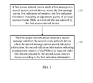
- the method includes: sending, by a first access network device, a first message to a second access network device, where the first message carries first indication information, the first indication information indicating an adjustment quantity of physical resource blocks PRBs in a first cell that are adjusted by the first access network device; and receiving, by the first access network device, a second message sent from the second access network device, where the second message carries second indication information, the second indication information indicating adjustment positions of PRBs of a radio link that are adjusted by the second access network device according to the first indication information.
- the steps may specifically include:
- the first indication information may be any information capable of indicating adjustment quantity or adjustment positions (indication of the adjustment positions means indication of the adjustment quantity) of PRBs in the first cell that are adjusted by the first access network device to the second access network device.
- the first indication information may include, for example, one or more types of the following information: frequency information of the resources in the first cell, bandwidth information of the resources in the first cell, the number of timeslots of the resources in the first cell, timeslot position information of the resources in the first cell, and timeslots offset information of the resources in the first cell that are adjusted by the first access network device.
- the first indication information may not include one or more of the above pieces of information, whereas a corresponding configuration mode may be determined between the first access network device and the second access network device in a default manner.
- the second access network device may consider by default that the frequencies of the resources in the first cell that are adjusted by the first access network device are start frequencies corresponding to downlink frequency bands in the cell, and the bandwidths of the resources in the first cell that are adjusted by the first access network device are bandwidths corresponding to downlink frequency bands in the cell, and the rest may be deduced likewise.
- one or more fixed resource adjustment schemes may also be protocol-defined between access network devices, resource adjustment scheme information may be directly interacted between access network devices, or only index information corresponding to the resource adjustment scheme is interacted between access network devices. In this way, information of resource adjustment is notified to a peer. Assuredly, if only one resource adjustment scheme is available, the peer only needs to be notified as whether to adjust resources.
- the second access network device may acquire, according to the indication of the first indication information, information of adjustment of PRBs in the first cell by the first access network device. For example, the second access network device may determine, according to the adjustment quantity of physical resource blocks PRBs in the first cell that are adjusted by the first access network device indicated in the first indication information, the adjustment positions where PRB configuration of the corresponding radio link is to be adjusted, and adjust the PRB configuration of the radio link according to the determined adjustment positions. In addition, the second access network device may also feed back information of the adjustment positions of the PRBs of the radio link adjusted by itself to the first access network device.
- the second access network device may determine, according to the adjustment positions of PRBs in the first cell that are adjusted by the first access network device indicated in the first indication information, the adjustment positions where PRB configuration of the corresponding radio link is to be adjusted, and adjust the PRB configuration of the radio link according to the determined adjustment positions.
- the second access network device may also feed back information of the adjustment positions of the PRBs of the radio link adjusted by itself to the first access network device.
- the first access network device may also send adjustment quantity information of the PRBs to the third access network device according to interference to the second access network device
- the second access network device may selectively sends adjustment position information of the PRBs to the third access network device
- the third access network device may also perform corresponding adjustment accordingly to reduce the interference.
- the first message carrying the first indication information may be, for example, an eNB configuration update message, a cell activation request message, other message defined in the standards, or a newly added message.
- the first message may also carry one or more types of the following information: usage information (for example, indicating that the resources are used to configure a cell access link in a cell, and/or a radio backhaul link, and/or, energy saving configuration) of the resources in the first cell that are adjusted by the first access network device, activation time information of adjustment of the resources in the first cell, and configuration information of the guard period between uplink and downlink.
- the first access network device may also receive usage status indication information of uplink and/or downlink resources of the second access network device; or receive usage status indication information of uplink and/or downlink resources of the second access network device and usage status indication information of uplink and/or downlink resources of an access network device neighboring to the second access network device, and accordingly acquire whether the uplink and/downlink resources on the second access network device are sufficient and acquire possible interference existing between the second access network and its neighbor access network device.
- the first access network device may also receive cell configuration capability information of the second access network device, where the cell configuration capability information may include transmitter configuration information (for example, the number of transmitters) and/or receiver configuration information (for example, the number of receivers); and/or receive cell configuration information of an inactivated cell sent from the second access network device, where the cell configuration information includes one or more types of the following information: public land mobile network (PLMN, Public Land Mobile Network) identifier, physical layer cell identifier, upper-layer cell identifier, cell mode information, and cell state information.
- PLMN Public Land Mobile Network
- the first access network device receives a second message sent from the second access network device, where the second message carries second indication information, the second indication information indicating adjustment positions of PRBs of at least one radio link that are adjusted by the second access network device according to the first indication information.
- the second indication information may also be any information capable of indicating adjustment positions (indication of the adjustment positions means indication of the adjustment quantity) of PRBs in the radio link that are adjusted by the second access network device to the first access network device.
- the second indication information includes, for example, one or more types of the following information: frequency information of the adjusted resources of the radio link, bandwidth information of the adjusted resources of the radio link, uplink and/or downlink timeslot position information of the adjusted resources of the radio link, and timeslots offset information of the adjusted resources of the radio link.
- the second message carrying the second indication information may be, for example, an eNB configuration update message, a cell activation response message, other message defined in the standards, or a newly added message.
- the second message further carries: usage information (for example, indicating that the resources are used to configure an access link in a cell, and/or a radio backhaul link, and/or energy saving configuration) of the adjusted resources of the radio link, and/or activation time information of adjustment of the resources of the radio link.
- the first access network device may monitor usage rate of the uplink/downlink PRBs in the first cell; if it is determined, according to the monitored usage rate of the uplink/downlink PRBs in the first cell, that redundant uplink/downlink PRBs exist in the first cell, the number of configured PRBs in the first cell may be reduced, and the first indication information may indicate the number of configured uplink/downlink physical resource blocks PRBs in the first cell to be reduced by the first access network device; if it is determined, according to the monitored usage rate of the uplink/downlink PRBs in the first cell, that the uplink/downlink physical resource blocks are insufficient, the first indication information may indicate the number of configured uplink/downlink physical resource blocks PRBs in the first cell to be increased by the first access network device; and after the second message sent from the second access network device is received, the number of configured uplink/downlink PRBs in the first cell may be increased.
- first access network device and the second access network device are both base stations
- information interaction may be implemented using a direct interface (for example, an X2 interface, an Iur interface, an Iub interface, or an air interface) between the base stations, or by using an indirect interface (for example, an S1 interface or an Iu interface) between the base stations.
- a direct interface for example, an X2 interface, an Iur interface, an Iub interface, or an air interface
- an indirect interface for example, an S1 interface or an Iu interface
- the first access network device after sending the first message to the second access network device or after receiving the second message sent from the second access network device, sends serving cell configuration update information to part of or all user terminals served by the first access network device by using a system message or dedicated signaling, where the serving cell configuration update information includes one or more types of the following information: uplink and/downlink frequency information of the adjusted resources in the first cell, uplink and/or downlink bandwidth information of the adjusted resources in the first cell, uplink and/or downlink position information of the mute timeslots after the resources in the first cell are adjusted, activation time information of adjustment of the resources in the first cell, and configuration information of the guard period between uplink and downlink.
- the UE may acquire information of resource adjustment in the first cell.
- the first access network device may also send neighbor cell configuration update information to part of or all user terminals served by the first access network device by using a system message or dedicated signaling, where the neighbor cell configuration update information may include one or more types of the following information: frequency information of resources in a neighbor cell, bandwidth information of the resources in the neighbor cell, uplink and/or downlink timeslot position information of the resources in the neighbor cell, and timeslots offset information of the resources in the neighbor cell that are adjusted by the second access network device; and activation time information of adjustment of the resources in the neighbor cell.
- the UE may acquire information of resource adjustment in the neighbor cell.
- the first access network device may also send radio backhaul link configuration information to part of or all user terminals served by the first access network device by using a system message or dedicated signaling, where the radio backhaul link configuration information includes one or more types of the following information: frequency information of adjusted resources of a radio backhaul link, bandwidth information of the adjusted resources of the radio backhaul link, timeslot position information of the adjusted resources of the radio backhaul link, timeslots offset information of the adjusted resources of the radio backhaul link, and activation time information of adjustment of the resources of the radio backhaul link.
- the UE may acquire information of resource adjustment of the radio backhaul link.
- a position relationship of uplink and/or downlink resources in the first cell that are adjusted by the first access network device satisfies a radio access link of a cell configured by the second access network device as compatible with time division duplexing (TDD, Time Division Duplexing) configuration; or a position relationship of uplink and downlink resources in the first cell that are adjusted by the first access network device satisfies a radio access link of a cell configured by the second access network device as compatible with non-TDD configuration.
- TDD Time Division Duplexing
- the second access network device may correspondingly configure a radio access link for a cell compatible with TDD configuration or correspondingly configure a radio access link for a cell compatible with non-TDD configuration at the positions of the uplink and/or downlink resources in the first cell that are adjusted by the first access network device.
- the first access network device may also carry a guard period configuration indication in the first message for instructing the second access network device to configure a guard period for a downlink radio access link and an uplink radio access link in a cell, where the guard period configuration indication is used to indicate that data is not transmitted on one or more neighbor downlink transmission symbols and/or uplink transmission symbols so that the one or more neighbor downlink transmission symbols and/or uplink transmission symbols are used as the guard period, or one or more neighbor downlink transmission symbols and/and uplink transmission symbols are shifted forward or backward by one or more symbols so that mute transmission symbols caused by shifting are used as the guard period.
- the second access network device may set the guard period accordingly. Assuredly, the second access network device may also self-define how to set a guard period.
- the resources adjusted by the first access network device are uplink resources in the first cell
- the adjusted uplink resources are used to configure a radio backhaul link between the first access network device and the second access network device
- downlink timeslot positions of the radio backhaul link configured between the first access network device and the second access network device satisfy part of or all downlink timeslot positions in TDD configuration-compatible mode on the first access network device and the second access network device
- uplink timeslot positions of the radio backhaul link configured between the first access network device and the second access network device satisfy part of or all uplink timeslot positions in TDD configuration-compatible mode on the first access network device and the second access network device.
- the second access network device may configure positions of the remaining uplink timeslots after the radio backhaul link is configured as uplink timeslots of the radio access link.
- timeslot positions of a downlink backhaul link configured between the first access network device and the second access network device are correspondingly part of or all uplink timeslot positions of a radio access link configured on the second access network device, where the uplink timeslot positions of the radio access link satisfy uplink timeslot positions in TDD configuration-compatible mode or in non-TDD configuration-compatible mode; timeslot positions of an uplink backhaul link configured between the first access network device and the second access network device are correspondingly part of or all downlink timeslot positions of the radio access link configured on the second access network device, where the downlink timeslot positions of the radio access link satisfy downlink timeslot positions in TDD configuration-compatible mode or in non-TDD configuration-compatible mode;
- the first access network device with redundant uplink and/or downlink resources in a cell adjusts resource configuration in the cell and provides part of or all the redundant resources in the cell for the second access network device neighboring to the first access network device to configure a radio access link and/or a radio backhaul link for the cell.
- the second access network device correspondingly adjusts, according to the adjustment of the resource configuration in the cell performed by the first access network device, resource configuration of the radio access link and/or the radio backhaul link of the cell. This mechanism helps improve usage efficiency of resources and enhance system performance and quality of service.
- the following describes, from the perspective of an access network device receiving a spectrum resource, an embodiment illustrating a method for adjusting configuration of a spectrum resource according to the present invention.
- the method includes: receiving, by a second access network device, a first message sent from a first access network device, where the first message carries first indication information, the first indication information indicating an adjustment quantity of physical resource blocks PRBs in a first cell that are adjusted by the first access network device; adjusting positions of PRBs of a radio link according to the adjustment quantity of physical resource blocks PRBs in the first cell that are adjusted by the first access network device indicated by the first indication information; and sending a second message to the first access network device, where the second message carries second indication information, the second indication information indicating adjustment positions of the PRBs of the radio link that are adjusted by the second access network device according to the first indication information.
- the second access network may send serving cell configuration update information to part of or all user terminals served by the second access network device by using a system message or dedicated signaling, where the serving cell configuration update information includes one or more types of the following information: uplink and/or downlink frequency information of adjusted resources of a cell radio access link, uplink and/or downlink bandwidth information of the adjusted resources of the cell radio access link, and activation time information of adjustment of the resources of the cell radio access link.
- the second access network device may also send neighbor cell configuration update information to part of or all user terminals served by the second access network device by using a system message or dedicated signaling, where the neighbor cell configuration update information includes one or more types of the following information: frequency information of the adjusted resources in the first cell, bandwidth information of the adjusted resources in the first cell, uplink and/or downlink timeslot position information of the adjusted resources in the first cell, timeslots offset information of the adjusted resources in the first cell, activation time information of adjustment of the resources in the first cell, and configuration information of guard period between uplink and downlink.
- the neighbor cell configuration update information includes one or more types of the following information: frequency information of the adjusted resources in the first cell, bandwidth information of the adjusted resources in the first cell, uplink and/or downlink timeslot position information of the adjusted resources in the first cell, timeslots offset information of the adjusted resources in the first cell, activation time information of adjustment of the resources in the first cell, and configuration information of guard period between uplink and downlink.
- the second access network device may also send radio backhaul link configuration update information to part or all user terminals served by the second access network device by using a system message or dedicated signaling, where the radio backhaul link configuration update information includes one or more types of the following information: frequency information of the adjusted resources of the radio backhaul link, bandwidth information of the adjusted resources of the radio backhaul link, uplink and/or downlink timeslot position information of the adjusted resources of the radio backhaul link, timeslots offset information of the adjusted resources of the radio backhaul link, and activation time information of adjustment of the resources of the radio backhaul link.
- a macro base station provides its redundant UL spectrum resource for a Pico base station to apply the resources to an access link thereof as an example.
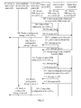
- a macro base station M1 and a macro base station M2 are neighbor base stations of a pico (Pico) base station P1, and another embodiment illustrating a method for adjusting configuration of a spectrum resource according to the present invention may specifically include:
- the base station in the network may collect statistics for the number of used uplink/downlink PRBs in one or more of its served cells within a unit duration (the unit duration may be several timeslots, several minutes, tens of minutes, or any other duration), and calculate the usage rate (the following uses R URB to indicate the usage rate of the uplink PRBs) of the uplink/downlink PRBs in the one or more cells within the unit duration.
- R URB is equal to the ratio of the number of used uplink PRBs in the cell within the unit duration to the total number of PRBs in the cell within the unit duration.
- the usage rate of the uplink/downlink PRBs may also be determined by the number of used PRBs.
- usage rate of PRBs number of used PRBs/total number of PRBs (determined by the cell bandwidth). This embodiment of the present invention uses the PRB usage rate as an example, and the number of used PRBs is similar, which is not detailed here again.
- R URB For details about the method for calculating R URB , reference may be made to FIG. 3 .
- the base station can calculate the number of used uplink PRBs with each two timeslots in a cell served by the base station, and R URB is equal to the ratio of the number of used uplink PRBs in 20 timeslots in the cell to the total number of uplink PRBs in 20 timeslots in the cell.
- redundancy decision thresholds R RB -1 for example, 90%, 80% or another value
- R RB -2 for example, 95%, 100% or another value
- the macro base station M1 and the Pico base station P1 may determine, according to the monitored usage rate of uplink/downlink PRBs in a cell, whether redundant uplink/downlink PRBs exist in the cell, or determine whether the uplink/downlink PRBs are insufficient.
- R DRB is equal to the ratio of the number of used downlink PRBs in the cell within a unit duration to the total number of downlink physical resource blocks in the cell within the unit duration. Therefore, the macro base station M1 and the Pico base station P1, optionally the macro base station M2 may also similarly determine, according to the monitored usage rate of downlink PRBs in a cell, whether redundant downlink PRBs exist in the cell, or determine whether the downlink PRBs are insufficient.
- the macro base station M1 and the Pico base station P1 interacts with each other for the usage status of the PRBs in their served cells.
- the macro base station M2 may also interact with the macro base station M1 and the Pico base station P1 for the usage status of the PRBs in their served cells.
- interaction of usage status of the PRBs in the neighbor cells may be implemented between base stations neighboring to each other in the network (i.e., neighbor base stations) by using a direct interface or an indirect interface (one or more) between the base stations, so that the base stations acquire the usage status of the PRBs in a neighbor cell according to the interaction information.
- neighbor base stations may interact with each other for the usage status of the PRBs in a neighbor cell periodically (the specific interaction period may be set according to specific scenarios) or under triggering by one or more trigger events.
- a trigger event C1 may be: the change amplitude of the usage rate of the uplink PRBs (and/or downlink PRBs) in a cell exceeds a preset threshold (for example, 20%, 40% or another value);
- a trigger event C2 may be: the change amplitude of the ratio of the uplink PRB usage rate to the downlink PRB usage rate exceeds a preset threshold (for example, 10%, 20% or another value).
- a cell (represented by a cell C m1 , the cell C m1 is a macro cell) served by the macro base station M1 and a cell (represented by a cell C p1 , the cell C p1 is a Pico cell) served by the Pico base station P1 are neighbor cells, and a cell (represented by a cell C m2 ) served by the macro base station M1 and the cell C p1 served by the Pico base station P1 are neighbor cells; the macro base station M1 and the Pico base station P1 may interaction with each other for the usage status of the uplink/downlink PRBs in the corresponding cells periodically or under triggering of the trigger event C1 and/or the trigger event C2, and the macro base station M1 may acquire whether the uplink/downlink PRBs in the cell C p1 served by the Pico base station P1 are sufficient.
- the macro base station M2 and the Pico base station P1 may also interact with each other for the usage status of the uplink/downlink PRBs in the corresponding cells periodically or under triggering of the trigger event C1 and/or the trigger event C2.
- the macro base station M1 and the Pico base station P1 may carry a usage status indication of PRBs in a load-related message, a radio resource status indication message, or other messages involved in interaction.
- the usage status indication may indicate the usage rate of uplink/downlink PRBs in a cell within a unit duration, or indicate the number of used uplink/downlink PRBs in a cell within a unit duration, or indicate whether redundant uplink/downlink PRBs exist in the cell, or indicate whether the uplink/downlink PRBs in the cell are insufficient, or indicate information capable of characterizing the usage status of the uplink/downlink PRBs.
- the base station acquires the usage status of PRBS in a neighbor cell according to the interaction information.
- Insufficiency of the downlink PRBs in a cell may be reflected by high usage rate of the downlink PRBs, or reflected by one or more pieces of the following information: Access class barring in a cell, poor quality of service of users in a cell, low user satisfaction in a cell.
- usage of averagely 10 (or another number) corresponding PRBs serves as a class, and the base stations performs interactions when the change amplitude of the used PRBs exceeds 10 (or another number) PRBs.
- Interaction of usage status of PRBs between base stations may also be implemented in a manner of index indication. This greatly reduces the signaling overhead for interaction between base stations.
- Table 1 exemplarily shows a corresponding relationship between the index and the number of used PRBs.
- index 0000 indicates that averagely 10 PRBs are used
- index 1000 indicates that averagely 90 PRBs are used
- the rest may be deduced likewise.
- the macro base station M1 adjusts configuration of PRBs in the cell C m1 to provide part of or all redundant PRBs in the macro cell C m1 for a Pico base station to apply the PRBs to an access link of the cell.
- the macro base station M1 decides whether to reduce the number of configured downlink PRBs in the cell C m1 .
- the decision may be performed with reference to one or more of the following three reference conditions:
- Reference condition 1 is mandatory, and reference conditions 2 and 3 are optional.
- the macro base station M1 may acquire usage status of PRBs in the cell C m1 and C p1 by using step 201 and step 202.
- the macro base station M1 may decide whether to adjust configuration of the PRBs in the cell C m1 according to reference condition 1, or reference conditions 1 and 2, or reference conditions 1 and 3, or reference conditions 1, 2 and 3.
- the macro base station M1 may determine to reduce the number of configured uplink PRBs in the cell C m1 to provide part of or all redundant PRBs in the cell C m1 for a Pico base station to apply the PRBs to an access link of the cell.
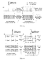
- FIG. 4-a For ease of understanding, the following gives further description using an assumption that the macro cell C m1 and the Pico cell C p1 are both FDD cells, and cell spectrum resource deployment in the initial network state may be illustrated in FIG 4-a or FIG. 4-b .
- deployment of uplink and downlink frequency bands in the macro cell C m1 and the Pico cell C p1 may be the same, with 20M bandwidth in both uplink and downlink frequency bands, that is, spectrum configuration in the block marked by dashed lines exists in the Pico cell.
- the deployment may be different, for example, spectrum configuration in the block marked by dashed lines does not exist in the Pico cell.
- the macro base station M1 may adjust positions (including quantity) of the PRBs in the macro cell C m1 in a plurality of manners according to redundancy of the uplink resources in the macro cell C m1 to reduce the number of configured uplink PRBs in the macro cell C m1 to provide part of or all redundant uplink PRBs in the macro cell C m1 for the Pico base station P1 to apply the PRBs to the cell access link thereof.
- the Pico base station P1 may correspondingly deploy one (or more) new cell (may be referred to as a cell C p2 ) in TDD configuration-compatible mode or non-TDD configuration-compatible mode according to position adjustment of the PRBs in the macro cell C m1 performed by the macro base station M1. It can be understood that the cell C p2 newly deployed by the Pico base station P1 and the macro cell C m1 are neighbor cells.
- the following describes changes of network deployment status by using a heterogeneous network as an example.
- the case of a homogeneous network is similar to that of the heterogeneous network.
- the macro base station M1 may reduce the number of subframes corresponding to all FDD uplink frequency bands in the macro cell C m1 to provide the redundant subframes for a neighbor cell C p2 to configure downlink timeslots. For example, network cell deployment status changes from the scenario illustrated in FIG. 4-a to the scenario illustrated in FIG. 4-c or FIG. 4d.
- the macro base station M1 adjusts positions of FDD uplink subframes in the macro cell C m1 so that the Pico base station P1 can deploy the new cell C p2 in TDD mode.
- FIG. 4-c uses a case where the macro base station M1 sets subframes 0, 1, 5 and 6 in the uplink subframes to null so that the Pico base station P1 configures the subframes to downlink subframes in the neighbor cell C p2 as an example for description.
- other TDD cell configuration modes may also be used, which are similar and thus not detailed here again.
- assignment ratio relationships between uplink and downlink timeslots include the following seven types.
- TDD-compatible configuration Any configuration mode satisfying the following seven timeslot assignment ratio relationships in the same frequency band is TDD-compatible configuration.
- Table 2 TDD Configuration Mode Uplink and Downlink Conversion Period Subframe Type (S/D/U) 0 1 2 3 4 5 6 7 8 9 0 5 ms D S U U U D S U U U 1 5 ms D S U U D D S U U D 2 5 ms D S U D D D S U D D 3 10 ms D S U U U D D D D D D 4 10 ms D S U U D D D D D D 5 10 ms D S U D D D D D D D D 6 5 ms D S U U U U D S U U U D S U U D
- FIG. 4-c is corresponding to TDD configuration 0 in Table 2.
- the macro cell C m1 does not send service data at the FDD uplink timeslot position corresponding to the downlink transmission timeslot in the cell C p2 , and may send control signaling on the uplink control channel corresponding to the timeslot.
- the Pico base station may serve only a cell on the FDD UL spectrums or serve other FDD cells besides the cell on the FDD UL spectrums. Positions of the uplink subframes in the FDD cell and the uplink subframes in the newly deployed cell share the same resources.
- the macro base station M1 adjusts positions of FDD uplink subframes in the macro cell C m1 so that the Pico base station P1 can deploy the new cell C p2 in non-TDD configuration-compatible mode (a flexible configuration mode).
- FIG. 4-d uses a case where the macro base station M1 sets the first four subframes in the uplink subframes to null so that the Pico base station P1 configures the subframes to downlink subframes in the neighbor cell C p2 .
- other non-TDD-compatible cell configuration modes may also be used, which are similar and thus not detailed here again.
- the base station sends signals to a user equipment in the downlink timeslots, the downlink signal will pass through specific channels, thereby resulting in a transmission delay when arriving at the user.
- the user equipment sends signals in the uplink timeslots.
- the signals will also arrive at the base station a specific transmission delay later.
- the user equipment needs to send the uplink signals to the base station in advance by the delay.
- the uplink and downlink transmission delays are the same, and the maximum transmission delay is related to the radius R of a cell.
- specific conversion time is needed for conversion from a signal receiving state to a signal sending state.
- a guard period (GP) between uplink and downlink may reuse the GP in the TDD system.
- the GP is reconfigured because a TDD configuration relationship failing to comply with the standard definition exists due to the downlink timeslots.
- the GP between the downlink timeslots to the uplink timeslots on the FDD UL carrier may be obtained in the following two manners:
- removing or shifting of the N symbols may be configured, or may be implemented by several preset configuration modes.
- the base station may notify the corresponding configuration mode or the index of the configuration mode to its served user equipment, and the user equipment acquires information of the GP configuration accordingly.
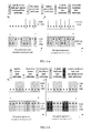
- the macro base station M1 may reduce the number of subframes corresponding to part of FDD uplink frequency bands in the macro cell C m1 to provide the redundant subframes to a neighbor cell C p2 for configuring downlink timeslots. For example, network cell deployment status changes from the scenario illustrated in FIG. 4-b to the scenario illustrated in FIG. 4-e, FIG. 4-f , FIG. 4-g or FIG. 4-h .
- the macro base station M1 adjusts positions of FDD uplink subframes in the macro cell C m1 so that the Pico base station P1 can deploy the new cell C p2 in TDD-compatible mode.
- FIG. 4-e and FIG. 4-f use a case where the macro base station M1 sets subframes 0, 1, 5 and 6 in the uplink subframes corresponding to part of its FDD uplink subcarriers to null so that the Pico base station P1 configures the subframes to downlink subframes in the neighbor cell C p2 as an example for description. Assuredly, other TDD-compatible cell configuration modes may also be used, which are similar and thus not detailed here again.
- the macro base station M1 adjusts positions of uplink subframes corresponding to part of the FDD uplink frequency bands in the macro cell C m1 so that the Pico base station P1 can also deploy the new cell C p2 in non-TDD-compatible mode (a flexible configuration mode).
- FIG. 4-g and FIG. 4-h use a case where the macro base station M1 sets first four subframes in the uplink subframes corresponding to part of its FDD uplink subcarriers to null so that the Pico base station P1 configures the subframes to downlink subframes in the neighbor cell C p2 as an example for description.
- other flexible non-TDD cell configuration modes may also be used, which are similar and thus not detailed here again.
- the Pico cell C p1 may not send data at the uplink transmission timeslot positions corresponding to the downlink transmission timeslots in the Pico cell C p2 , which is illustrated in FIG. 4-e, FIG. 4-f , FIG. 4-g or FIG. 4-h .
- control signaling may be sent in the set-null (removed) timeslots.
- the Pico cell C p1 may send data and control signaling at the uplink timeslot positions corresponding to the downlink timeslots in the Pico cell C p2 .
- service data may not be transmitted at the uplink transmission timeslot positions in the macro cell C m1 with a frequency neighboring to that of the downlink transmission timeslots in the Pico cell C p2 to prevent mutual interference, which is, for example, illustrated in FIG. 4-f or FIG. 4-h .
- control signaling may be sent in the set-null (removed) timeslots.
- the change of assignment ratio of different TDD uplink and downlink subframes in the macro cell and/or Pico cell may be as shown in Table 4 (assume that each of the two subcarrier frequency bands has 10 subframes).
- the change of assignment ratio of different TDD uplink and downlink subframes in the macro cell and/or Pico cell may be as shown in Table 5 (assume that each of the two subcarrier frequency bands has 10 subframes).
- the macro base station M1 may determine, according to interference conditions and/or the number of redundant PRBs, an adjustment mode to be used, and adjust the uplink PRBs in the macro cell C m1 .
- the macro base station M1 sends a message ms1 (for example, an eNB configuration update message, or a cell activation message, or another message) to the Pico base station P1.
- a message ms1 for example, an eNB configuration update message, or a cell activation message, or another message
- the macro base station M1 may, for example, notify information of resource adjustment in the macro cell C m1 to the Pico base station P1 by using the eNB configuration update message or the cell activation message (message ms1) so that the Pico base station P1 configures a new Pico cell C p1 according to the information of resource adjustment in the macro cell C m1 .
- the eNB configuration update message or the cell activation message may carry indication information indicating an adjustment quantity of physical resource blocks PRBs in the cell C m2 that are adjusted by the macro base station M1, where the indication information may include one or more types of the following information: frequency information of the resources in the macro cell C m1 that are adjusted by the macro base station M1, bandwidth information of the resources in the macro cell C m1 that are adjusted by the macro base station M1, the number of timeslots of the resources in the macro cell C m1 that are adjusted by the macro base station M1, timeslot position information of the resources in the macro cell C m1 that are adjusted by the macro base station M1, configuration information of the guard period between uplink and downlink, subframe offset information of the resources in the macro cell C m1 that are adjusted by the macro base station M1.
- the eNB configuration update message or the cell activation message may further carry: usage information (for example, indicating that the resources are used to configure a radio backhaul link, or an access link in a Pico cell, or energy saving configuration) of the resources in the macro cell C m1 that are adjusted by the macro base station M1, and/or activation time information of adjustment of the resources in the macro cell C m1 .
- the eNB configuration update message or the cell activation message (message ms1) may further carry: a guard period configuration indication for instructing the Pico base station P1 to configure a guard period for a downlink radio access link and an uplink radio access link in a cell, where the guard period configuration indication may be used to indicate that data is not transmitted on one or more neighbor downlink transmission symbols and/or uplink transmission symbols so that the one or more neighbor downlink transmission symbols and/or uplink transmission symbols are used as the guard period, or one or more neighbor downlink transmission symbols and/and uplink transmission symbols are shifted forward or backward by one or more symbols so that mute transmission symbols caused by shifting are used as the guard period.
- the eNB configuration update message or the cell activation message may not carry one or more pieces of the above information, and corresponding configuration may be acknowledged between base stations in a default manner.
- the indication information does not include frequency information or bandwidth information of the resources in the macro cell C m1 that are adjusted by the macro base station M1
- the Pico base station P1 may consider by default the frequencies of the resources in the macro cell C m1 that are adjusted by the macro base station M1 as start frequencies corresponding to the downlink frequency bands in the cell, and the bandwidths of the resources in the macro cell C m1 that are adjusted by macro base station M1 are bandwidths corresponding to downlink frequency bands in the cell, and the rest may be deduced likewise.
- one or more fixed resource adjustment schemes may also be protocol-defined between base stations, resource adjustment scheme information may be directly interacted between base stations, or only index information corresponding to the resource adjustment scheme is interacted. In this way, information of resource adjustment is notified to a peer. Assuredly, if only one resource adjustment scheme is available, the peer only needs to be notified as whether to adjust resources.
- the macro base station M1 sends a message ms2 (for example, an eNB configuration update message, or a cell activation message, or another message) to the macro base station M2.
- a message ms2 for example, an eNB configuration update message, or a cell activation message, or another message
- the macro base station M1 may also, for example, notify information of resource adjustment in the macro cell C m1 to the macro base station M2 by using the eNB configuration update message or the cell activation message (message ms2).
- the eNB configuration update message or the cell activation message may carry indication information indicating an adjustment quantity of physical resource blocks PRBs in the macro cell C m1 that are adjusted by the macro base station M1, where the indication information may include one or more types of the following information: frequency information of the resources in the macro cell C m1 that are adjusted by the macro base station M1, bandwidth information of the resources in the macro cell C m1 that are adjusted by the macro base station M1, the number of timeslots of the resources in the macro cell C m1 that are adjusted by the macro base station M1, timeslot position information of the resources in the macro cell C m1 that are adjusted by the macro base station M1, configuration information of the guard period between uplink and downlink, subframe offset information of the resources in the macro cell C m1 that are adjusted by the macro base station M1.
- the eNB configuration update message or the cell activation message may further carry: usage information (for example, indicating that the resources are used to configure an access link in a Pico cell, or a radio backhaul link, or energy saving configuration) of the resources in the macro cell C m1 that are adjusted by the macro base station M1, and/or activation time information of adjustment of the resources in the macro cell C m1 .
- the eNB configuration update message or the cell activation message may not carry one or more pieces of the above information, and corresponding configuration may be acknowledged between base stations in a default manner.
- the indication information does not include frequency information or bandwidth information of the resources in the macro cell C m1 that are adjusted by the macro base station M1
- the macro base station M2 may consider by default the frequencies of the resources in the macro cell C m1 that are adjusted by the macro base station M1 as start frequencies corresponding to the downlink frequency bands, and the bandwidths of the resources in the macro cell C m1 that are adjusted by macro base station M1 are bandwidths corresponding to downlink frequency bands in the cell, and the rest may be deduced likewise.
- one or more fixed resource adjustment schemes may also be protocol-defined between base stations, resource adjustment scheme information may be directly interacted between base stations, or only index information corresponding to the resource adjustment scheme is interacted. In this way, information of resource adjustment is notified to a peer. Assuredly, if only one resource adjustment scheme is available, the peer only needs to be notified as whether to adjust resources.
- the macro base station M2 may changes configuration of uplink PRBs in the neighbor cell of the cell C P2 served by the macro base station M2 by using the eNB configuration update message or the cell activation message (message ms2), to prevent interference caused to the cell.
- information interaction may be implemented between the macro base station M1, the macro base station M2 and the Pico base station P1 by using a direct interface between the base stations, for example, an X2 interface, an Iur interface, an Iub interface or an air interface, or by using an indirect interface between the base stations, for example, an S1 interface or an Iu interface.
- a direct interface between the base stations for example, an X2 interface, an Iur interface, an Iub interface or an air interface
- an indirect interface between the base stations for example, an S1 interface or an Iu interface.
- the macro base station M1 informs a UE camping in the cell C m1 of the configuration change in the cell C m1 .
- the macro base station M1 when the macro base station M1 changes or intends to change configuration of the uplink resources in the cell C m1 , if part of its served UEs (for example, UE in version R10) support the new configuration mode of the UL subframes in the cell C m1 , and when a special HARQ feedback design is made for the new configuration of the uplink subframes in the cell C m1 , the macro base station M1 may notify the changed configuration of the UL subframes (timeslots) in the cell C m1 to the UE in a latest version at the air interface in broadcast mode or unicast mode. However, such notification cannot be implemented for the UE in an earlier version.
- the macro base station M1 may send serving cell update configuration information to part of or all UEs served by the macro base station M1, where the serving cell update configuration information includes one or more types of the following information:
- the Pico base station may be configured with non-TDD configuration-compatible cells
- information may be notified at an air interface by the macro base station M1 to its served UEs in a latest version in broadcast mode (by using a system broadcast message) and in unicast mode (by using a dedicated signaling message).
- the macro base station M1 may place configuration information of the uplink mute subframes (timeslots) in the cell C m1 onto a SIB2.
- the format of the information is as follows:
- the macro base station M1 may place configuration information of the downlink mute subframes in the cell C m1 onto a MIB or the SIB2.
- the configuration information is placed on the MIB in the following format:
- information of the uplink and downlink mute subframes in the cell C m1 may be carried in a plurality of types of downlink signalings, for example, a paging message, a connection establish message, a connection reconfigure message, a connection re-establish message, and a downlink message transmission message.
- the Pico base station P1 configures a new Pico cell C P2 .
- the Pico base station P1 determines, according to the uplink resources provided by the macro cell C m1 , and interference caused by a neighbor cell to the macro cell C m1 , to use the uplink resources provided by the macro cell C m1 to deploy the Pico cell C P2 .
- Deployment of the new Pico cell C P2 may be considered as adjustment of the resources of the radio access link in the cell from none to availability, or additionally adjustment from one configuration to another.
- Uplink and downlink subframe (timeslot) assignment ratio in the newly deployed Pico cell C P2 are uplink and downlink subframe (timeslot) assignment ratio in the newly deployed Pico cell C P2 :
- the following mainly uses the case of configuring the Pico cell C P2 to a TDD configuration-compatible cell (that is, newly deploying a TDD cell by the Pico base station P1) as an example for description.
- uplink and downlink configuration in the case of configuring the Pico cell C P2 to a non-TDD configuration-compatible cell that is, flexible uplink and downlink configuration is similar.
- FDD UL of the macro cell C m1 can provide four downlink subframes. Because the S subframe is also considered as a downlink subframe, the four downlink subframes provided by FDD UL may include two DL subframes and two S subframes, or three DL subframes and one S subframe. In this case, the corresponding TDD configuration in Table 2 is configuration mode 0.
- the macro base station M1 may determine not to send service data in which subframes (timeslots) of part of or all uplink frequency bands in the macro cell C m1 according to the position relationship between uplink and downlink subframes (timeslots) in the TDD Pico cell C P2 configured by the Pico base station.
- positions of the uplink and downlink subframes in the Pico cell C P2 may be determined by a valid HARQ time sequence, for example, FDD or TDD, or a combination of FDD and TDD, or a newly defined time sequence.
- Previously, hardware processing capabilities (including transmission and reception capabilities, for example, the number of transmitters and/or receivers) or inactivated and incomplete cell configuration information may also be interacted between base stations.
- the information indicating that the base station may be added with a cell but does not have the cell configuration capability for the spectrum resource may also be notified to the neighbor base station.
- the interaction information may be sent during establishment of an interface between base stations, or may be interacted in subsequent interface signalings.
- the macro base station M1 (a base station providing resources) acquires that the Pico base station P1 has the capability of newly adding a transmission channel, the macro base station M1 may send a message to the Pico base station P1 in a well-targeted manner and provide FDD UL frequency band resources for the Pico base station P1.
- Part of configuration information of the cell C P2 (although before configuration of uplink and downlink resources, the cell C P2 is not running and in the deactivated state) may be configured on the Pico base station P1, and the Pico base station P1 may interact with neighbor base stations (including the macro base station M1 and the macro base station M2).
- the part of configuration information of the cell C P2 interacted between the base stations may include one or more types of the following information:
- the base station capable of providing resources sends FDD UL resource providing information to part of or all neighbor base stations, and the neighbor base station having the corresponding hardware processing capability is capable of making a response.
- the macro base station M1 (a base station providing uplink FDD UL resources) sends an eNB configuration update message (message ms1) to the Pico base station P1 (a base station receiving uplink resources).
- the eNB configuration update message carries configuration of the adjusted FDD uplink resources in the macro cell C m1 provided by the macro base station M1, and indicates usage information of the adjusted uplink resources.
- the macro base station M1 may send specific TDD cell configuration to the Pico base station P1 by using the FDD information in serving cell information modified in the first eNB configuration update message (message ms1). That is, the macro base station M1 determines TDD configuration of a neighbor cell.
- the details are as shown in Table 6, which are, however, not limited thereto.
- muted subframe configuration may be indicated not using bitmap, but using a corresponding TDD configuration mode, that is, indicating one of TDD configuration 0 to TDD configuration 6.
- Timeslot positions corresponding to the TDD downlink subframes are timeslot positions of the UL subframes in the macro cell C m1 that are muted by the macro base station M1.
- the Pico base station P1 may correspondingly configure the frequency and bandwidth for a TDD cell according to the uplink frequency and bandwidth in the mute uplink configuration.
- the macro base station M1 may define specific timeslot positions of the mute subframes in the mute subframe configuration information.
- the neighbor cell of the Pico base station P1 may directly determine, according to the timeslot positions of the mute subframes, an uplink and downlink assignment ratio and the start position of the configuration of the TDD cell. Then, the Pico base station P1 configures parameters such as ECGI, PCI, TAC, and PLMN for the cell, and sends an eNB configuration update message to the neighbor base station.
- the number of subframes may only be configured in the Mute subframe configuration.
- Specific TDD cell configuration is determined by the Pico base station P1 configuring the TDD cell.
- the macro base station M1 performs non-scheduling operation (mute) for the uplink subframes in the macro cell C m1 according to the positions of the downlink subframes in the TDD cell configured by the Pico base station P1.
- the Pico base station P1 may carry detailed configuration information of a new cell in the eNB configuration update message, as shown in Table 9.
- the Pico base station P1 configures the new cell in TDD mode or non-TDD-compatible mode.
- CP In the TDD-compatible configuration mode, besides the frequency, bandwidth, TDD assignment ratio and special subframe configurations, CP is also configured. Additional configurations such as subframe configuration quantity and activation time for configuration validation may also be needed.
- mute symbol may be configured to be uplink symbols or downlink symbols, or mute several symbols.
- moving symbols are configured to be uplink symbols or downlink symbols, or move several symbols.
- Scheduled SRS configuration may include whether to perform SRS configuration, and the number of configured SRS symbols.
- the macro base station M1 may also indicate cell configuration added by the Pico base station P1; when indication instructing the neighbor Pico base station P1 to adjust configuration of a new cell is displayed, configuration of cells to be activated are added in the cell activation request message.
- the specific IE configuration is shown in Table 10, which is, however, not limited hereto.
- the Pico base station P1 may feed back acknowledgement of the adjusted cell configuration to the macro base station M1 by using X2 signaling, S1 signaling, air interface signaling, Iu signaling, Iur signaling, or Iub signaling, for example, feed back the acknowledgement of the adjusted cell configuration to the macro base station M1 by using a cell activation response message or an eNB configuration update message.
- X2 signaling S1 signaling
- S1 signaling air interface signaling
- Iu signaling Iur signaling
- Iub signaling for example, feed back the acknowledgement of the adjusted cell configuration to the macro base station M1 by using a cell activation response message or an eNB configuration update message.
- the macro base station M1 may not specify specific configurations, but only indicates part of cell configurations, and the Pico base station P1 determines how to adjust the configuration of a cell.
- the specific configurations are as shown in Table 12.
- the Pico base station P1 needs to feedback specific cell configuration information in the corresponding information for adjusting cell activation, and then provides the configuration information for the macro base station M1 to configure non-scheduling uplink subframes in the macro cell C m1 according to the cell configuration fed back by the Pico base station P1.
- the Pico base station P1 sends a message ms12 (for example, an eNB configuration update response message, or a cell activation response message, or another message) to the macro base station M1.
- a message ms12 for example, an eNB configuration update response message, or a cell activation response message, or another message
- the Pico base station may notify configuration of the new Pico cell C P2 to the macro base station M1 by using the eNB configuration update response message or the cell activation response message (message ms12).
- the Pico base station P1 may carry, in the eNB configuration update response message or the cell activation response message (message ms12), one or more types of the following information: frequency information of the radio access link resources in the Pico cell C P2 , bandwidth information of the radio access link resources in the Pico cell C P2 , timeslot position information of the radio access link resources in the Pico cell C P2 , and subframe offset information of the radio access link resources in the Pico cell C P2 that are adjusted by the Pico base station P1.
- the message may further carry one or more of types of the following information: usage information of the adjusted resources of the radio link, activation time information of adjustment of the resources of the radio link, and configuration information of the guard period between uplink and downlink.
- the Pico base station P1 notifies the configuration change in the cell to the UE served by the Pico base station P1.
- the Pico base station P1 may send serving cell configuration update information to part of or all user terminals (for example, the cell configuration change is notified to only UEs in latest versions such as R10 or the cell configuration change is notified to all UEs) served by the Pico base station P1 by using a system message or dedicated signaling, where the serving cell configuration update information includes one or more types of the following information: uplink and/or downlink frequency information of the adjusted resources in the Pico cell C P2 , uplink and/or downlink bandwidth information of the adjusted resources in the Pico cell C P2 , activation time information of adjustment of the resources in the Pico cell C P2 , and configuration information of the guard period between uplink and downlink.
- the serving cell configuration update information includes one or more types of the following information: uplink and/or downlink frequency information of the adjusted resources in the Pico cell C P2 , uplink and/or downlink bandwidth information of the adjusted resources in the Pico cell C P2 , activation time information of adjustment of the resources in the Pico cell C
- the Pico base station P1 may also send neighbor cell configuration update information to part of or all user terminals served by the Pico base station P1 by using a system message or dedicated signaling, where the neighbor cell configuration update information includes one or more types of the following information: frequency information of the adjusted resources in the neighbor cell C m1 , bandwidth information of the adjusted resources in the neighbor cell C m1 , timeslot position information of the adjusted resources in the neighbor cell C m1 , subframe offset information of the adjusted resources in the neighbor cell C m1 that are adjusted by the macro base station M2, and configuration information of the guard period between uplink and downlink; and activation time information of adjustment of the resources in the neighbor cell C m1 .
- the UE may perform HARQ feedback, measurement control and neighbor cell detection accordingly.
- the dedicated signaling may also include an RRC connection reconfigure message or an RRC connection establish or re-establish message.
- the macro base station M2 sends a message ms12 (for example, an eNB configuration update response message, or a cell activation response message, or an eNB configuration update message, or another message) to the macro base station M1.
- a message ms12 for example, an eNB configuration update response message, or a cell activation response message, or an eNB configuration update message, or another message
- the macro base station M2 may also notify the configuration change in a neighbor cell of the cell C P2 to the UE served by the macro base station M2.
- the macro base station M2 may also send neighbor cell configuration update information to part of or all user terminals served by the macro base station M2 by using a system message or dedicated signaling, where the neighbor cell configuration update information includes one or more types of the following information: frequency information of the resources in the neighbor cell, bandwidth information of the resources in the neighbor cell, uplink and/or downlink timeslot position information of the resources in the neighbor cell, timeslots offset information of the resources in the neighbor cell that are adjusted by the Pico base station P1, and configuration information of the guard period between uplink and downlink; and activation time information of adjustment of the resources in the neighbor cell.
- the neighbor cell configuration update information includes one or more types of the following information: frequency information of the resources in the neighbor cell, bandwidth information of the resources in the neighbor cell, uplink and/or downlink timeslot position information of the resources in the neighbor cell, timeslots offset information of the resources in the neighbor cell that are adjusted by the Pico base station P1, and configuration information of the guard period between uplink and downlink; and activation time information of adjustment of the resources in
- the Pico base station P1, the macro base station M1, and the macro base station M2 interact with each other for usage status of UL/DL PRBs.
- the Pico base station P1 may interact with the macro base station M1 and the macro base station M2 for the usage status of the UL/DL PRBs in the cell C P2 under triggering of a trigger event C1 and/or a trigger event C2.
- the macro base station M1 prepares to adjust configuration of UL PRBs in the macro cell C m1 .
- the macro base station M1 if determining, according to the monitored usage status of uplink PRBs in the cell C m1 , that redundant uplink PRBs exist in the cell C m1 , the macro base station M1 reduces the number of configured uplink PRBs in the cell C m1 ; if determining, according to the monitored usage status of uplink PRBs in the cell C m1 , that uplink physical resource blocks in the cell C m1 are insufficient, the macro base station M1 increases the number of configured uplink PRBs in the cell C m1 .
- the macro base station M1 may firstly instruct the Pico base station P1 to reduce the number of configured downlink PRBs in the Pico cell C p2 , and increase the number of configured uplink PRBs in the cell C m1 after the Pico base station P1 correspondingly reduces the number of configured downlink PRBs in the Pico cell C p2 .
- the macro base station M1 sends a message ms3 (for example, an eNB configuration update message, or a cell activation message, or another message) to the Pico base station P1.
- a message ms3 for example, an eNB configuration update message, or a cell activation message, or another message
- the macro base station M1 may also inform the Pico base station P1 of information of resource adjustment in the macro cell C m1 by using the eNB configuration update message or the cell activation message (message ms3).
- the eNB configuration update message or the cell activation message may carry indication information indicating an adjustment quantity of physical resource blocks PRBs in the macro cell C m1 that are adjusted by the macro base station M1, where the indication information may include one or more types of the following information: frequency information of the resources in the macro cell C m1 that are adjusted by the macro base station M1, bandwidth information of the resources in the macro cell C m1 that are adjusted by the macro base station M1, the number of timeslots of the resources in the macro cell C m1 that are adjusted by the macro base station M1, timeslot position information of the resources in the macro cell C m1 that are adjusted by the macro base station M1, configuration information of the guard period between uplink and downlink, subframe offset information of the resources in the macro cell C m1 that are adjusted by the macro base station M1.
- the eNB configuration update notification message or the cell activation message may further carry: usage information (for example, indicating that the resources are used to configure an access link in a Pico cell, or a radio backhaul link, or energy saving configuration) of the resources in the macro cell C m1 that are adjusted by the macro base station M1, and/or activation time information of adjustment of the resources in the macro cell C m1 .
- the macro base station M1 sends a message ms4 (for example, an eNB configuration update message, or a cell activation message, or another message) to the macro base station M2.
- a message ms4 for example, an eNB configuration update message, or a cell activation message, or another message
- the macro base station M1 may also, for example, notify information of resource adjustment in the macro cell C m1 to the macro base station M2 by using the eNB configuration update message or the cell activation message (message ms4).
- the eNB configuration update message or the cell activation message may carry indication information indicating an adjustment quantity of physical resource blocks PRBs in the macro cell C m1 that are adjusted by the macro base station M1, where the indication information may include one or more types of the following information: frequency information of the resources in the macro cell C m1 that are adjusted by the macro base station M1, bandwidth information of the resources in the macro cell C m1 that are adjusted by the macro base station M1, the number of timeslots of the resources in the macro cell C m1 that are adjusted by the macro base station M1, timeslot position information of the resources in the macro cell C m1 that are adjusted by the macro base station M1, configuration information of the guard period between uplink and downlink, subframe offset information of the resources in the macro cell C m1 that are adjusted by the macro base station M1.
- the eNB configuration update message or the cell activation message may further carry: usage information (for example, indicating that the resources are used to configure an access link in a Pico cell, or a radio backhaul link) of the resources in the macro cell C m1 that are adjusted by the macro base station M1, and/or activation time information of adjustment of the resources in the macro cell C m1 .
- the macro base station M2 may changes configuration of uplink PRBs in the neighbor cell of the cell C P2 served by the macro base station M2 according to the eNB configuration update message or the cell activation message (message ms4), to prevent interference.
- the Pico base station P1 adjust configuration of the Pico cell C P2 .
- the Pico base station P1 may determine, according to information of the adjusted resource configuration in the macro cell C m1 and interference caused by a neighbor cell to the macro cell C m1 , how to adjust resource configuration in the Pico cell C P2 .
- the Pico base station P1 may correspondingly increase the number of configured downlink PRBs in the Pico cell C P2 , or may not change the number of configured downlink PRBs in the Pico cell C P2 ; if the macro base station M1 increases the number of configured uplink PRBs in cell C m1 , the Pico base station P1 may correspondingly reduce the number of configured downlink PRBs in the Pico cell C P2 .
- the Pico base station P1 sends a message ms32 (for example, an eNB configuration update response message, or a cell activation response message, or an eNB configuration update message, or another message) to the macro base station M1, and notifies the updated configuration of the cell C P2 to the macro base station M1.
- a message ms32 for example, an eNB configuration update response message, or a cell activation response message, or an eNB configuration update message, or another message
- the macro base station M2 sends a message ms42 (for example, an eNB configuration update response message, or a cell activation response message, or an eNB configuration update message, or another message) to the macro base station M1, and notifies the updated configuration of the neighbor cell to the macro base station M1.
- a message ms42 for example, an eNB configuration update response message, or a cell activation response message, or an eNB configuration update message, or another message
- the Pico base station P1 notifies the configuration change in the cell C P2 to the UE served by the Pico base station P1.
- the macro base station M2 may also notify the cell configuration change to the UE camping in a neighbor cell of the cell C P2 .
- the macro base station M1 changes the configuration of the cell C m1 .
- the macro base station M1 notifies the configuration change in the cell C m1 to the UE served by the macro base station M1.
- the macro base station with redundant uplink resources in a served cell adjusts resource configuration in the cell and provides part of or all the redundant resources in the cell for a Pico base station neighboring to the macro base station to configure a radio access link and/or a radio backhaul link for the cell.
- the Pico base station correspondingly adjusts, according to the adjustment of the resource configuration in the cell performed by the macro base station, resource configuration of the radio access link of the cell. This mechanism helps improve usage efficiency of resources and enhance system performance and quality of service.
- a macro base station provides its redundant UL/DL spectrum resource for a Pico base station to apply the resources to a radio access link and a radio backhaul link thereof.
- a macro base station M1 and a macro base station M2 are neighbor base stations of a Pico base station P1
- another embodiment illustrating a method for adjusting configuration of a spectrum resource according to the present invention may specifically include:
- Steps 501-502 are similar to steps 201-202 in terms of implementation mode.
- the macro base station M1 adjusts configuration of PRBs in the cell C m1 to provide part of or all redundant PRBs in the macro cell C m1 for a Pico base station to form the radio access link and the radio backhaul link of the cell.
- the macro base station M1 decides whether to reduce the number of configured PRBs in the cell C m1 .
- the decision may be performed with reference to one or more of the following three reference conditions:
- Reference condition 1 is mandatory, and reference conditions 2 and 3 are optional.
- the macro base station M1 may acquire usage status of PRBs in the cell C m1 and the cell C p1 by using step 201 and step 202.
- the macro base station M1 may decide whether to adjust configuration of the PRBs in the cell C m1 according to reference condition 1, or reference conditions 1 and 2, or reference conditions 1 and 3, or reference conditions 1, 2 and 3.
- the macro base station M1 may determine to reduce the number of configured downlink PRBs in the cell C m1 to provide part of or all redundant PRBs in the cell C m1 for a Pico base station to form an access link of the cell.
- FIG. 4-a For ease of understanding, the following gives further description using an assumption that the macro cell C m1 and the Pico cell C p1 are both FDD cells, and cell spectrum resource deployment in the initial network state may be illustrated in FIG 4-a or FIG. 4-b .
- deployment uplink and downlink frequency bands in the macro cell C m1 and the Pico cell C p1 may be the same, with 20M bandwidth at both uplink and downlink frequency bands, that is, spectrum configuration in the block marked by dashed lines exists in the Pico cell.
- the deployment may be different, for example, spectrum configuration in the block marked by dashed lines does not exist in the Pico cell.
- the macro base station M1 may adjust positions (including quantity) of the PRBs in the macro cell C m1 in a plurality of manners according to redundancy of the uplink resources in the macro cell C m1 to reduce the number of configured uplink PRBs in the macro cell C m1 and provide part of or all redundant uplink PRBs in the macro cell C m1 for the Pico base station P1 to apply the PRBs to the cell access link and radio backhaul link thereof.
- the Pico base station P1 may correspondingly deploy a new cell (may be referred to as a cell C p2 ) in TDD mode or non-TDD-compatible mode and the radio backhaul link according to position adjustment of the PRBs in the macro cell C m1 performed by the macro base station M1. It can be understood that the cell C p2 newly deployed by the Pico base station P1 and the macro cell C m1 are neighbor cells.
- the following describes changes of network deployment status by using a heterogeneous network as an example.
- the case of a homogeneous network is similar to that of the heterogeneous network.
- the macro base station M1 may reduce the number of subframes corresponding to all FDD uplink frequency bands in the macro cell C m1 to provide the redundant subframes for the Pico base station P1 to configure downlink timeslots for a neighbor cell C p2 .
- network cell deployment status changes from the scenario illustrated in FIG. 4-a to the scenario illustrated in FIG. 6-a .
- the macro base station M1 adjusts positions of the FDD uplink subframes in the macro cell C m1 , so that the Pico base station P1 can deploy a new radio backhaul link, where the spectrum resources of the radio backhaul absolutely come from the FDD UL frequency bands.
- the uplink and downlink links of the radio backhaul and the UL feedback link of the FDD system share the FDD uplink frequency bands in time-division mode.
- the uplink and downlink links of the radio backhaul and the UL feedback link of the FDD system share the FDD uplink frequency bands in time-division mode.
- subframes 0-9 in the FDD DL frequency band in the macro cell are used;
- parts of subframes in the FDD UL frequency band are used, including subframes 2-4 and 7-9.
- the uplink of the radio backhaul link and the uplink access link of the macro cell C m2 multiplex the same uplink timeslots.
- the multiplexing may be based on frequency division, time division or resource block division.
- subframes 0-9 in the FDD DL frequency band in the pico cell are used;
- parts of subframes in the FDD UL frequency band in the pico cell are used, including subframes 3 and 8.
- part of subframes in the FDD UL frequency band are used, including subframes 0-1 and subframes 5-6 in the FDD UL frequency band in the macro cell, and subframes 0-1 and subframes 5-6 in the FDD UL frequency band in the pico cell;
- part of subframes in the FDD UL frequency band are used, including: subframes 2 and 4 and subframes 7 and 9 in the FDD UL frequency bands in the macro cell and the pico cell.
- the macro base station M1 may adjust the number of subframes in the FDD uplink and downlink frequency bands in the macro cell C m1 , to provide the redundant subframes for the Pico base station P1 to configure the radio backhaul link and uplink and downlink timeslots in the neighbor cell C p2 .
- network cell deployment status changes from the scenario illustrated in FIG. 4-a to the scenario illustrated in FIG. 6-b .
- the spectrum resources of the radio backhaul link come from the FDD DL and UL frequency bands.
- the downlink backhaul link and the DL access link of the FDD system share the FDD downlink frequency band, and meanwhile the uplink backhaul link and the UL access link of the FDD system share the FDD uplink frequency band.
- FIG. 6-b illustrates the scenario illustrated in FIG. 6-b :
- the downlink access link in the macro cell and the downlink backhaul link may be multiplexed in time-domain, frequency-domain, or resource block mode;
- the uplink access link in the macro cell and the uplink backhaul link may be multiplexed in time-domain, frequency-domain, or resource block mode.
- Access link in the Pico cell where the Pico cell has two access links:
- part of subframes in the FDD DL frequency band in the Pico cell are used, including subframes 0-1, and subframes 5-6;
- part of subframes in the FDD UL frequency band in the Pico cell are used, including subframes 2-4, and subframes 7-9.
- part of subframes in the FDD UL frequency band in the Pico cell are used, including subframes 0-1, and subframes 5-6;
- part of subframes in the FDD UL frequency band in the Pico cell are used, including subframes 2-4, and subframes 7-9;
- part of subframes in the FDD DL frequency band are used, including subframes 2-4 and subframes 7-9 in the FDD DL frequency band in the macro cell, and subframes 2-4 and subframes 7-9 in the FDD DL frequency band in the pico cell;
- the UL (from a pico cell to a macro cell): part of subframes in the FDD UL frequency band are used, including subframes 0-1 and subframes 5-6 in the FDD UL frequency band in the macro cell, and subframes 0-1 and subframes 5-6 in the FDD UL frequency band in the pico cell.
- the downlink access link (from a Pico cell to a UE) and the uplink radio backhaul link (from a Pico cell to a Macro cell) in the Pico cell multiplex the same subframe timeslots (subframes 0-1 and subframes 5-6).
- the multiplexing may be based on frequency division, time division or resource block division.
- the access link adjusted in FIG. 6-c satisfies a non-TDD-compatible configuration relationship, and may be considered as a flexible configuration relationship.
- FIG. 6-c In the scenario illustrated in FIG. 6-c :
- the downlink access link in the macro cell and the downlink backhaul link may be multiplexed in time-domain, frequency-domain, or resource block mode;
- the uplink access link in the macro cell and the uplink backhaul link may be multiplexed in time-domain, frequency-domain, or resource block mode;
- parts of subframes in the FDD DL frequency band in the Pico cell are used, including subframes 0-3.
- parts of subframes in the FDD UL frequency band in the Pico cell are used, including subframes 0-3;
- part of subframes in the FDD DL frequency band are used, including subframes 4-9 in the FDD DL frequency band in the macro cell, and subframes 4-9 in the FDD DL frequency band in the pico cell;
- the UL (from a pico cell to a macro cell): part of subframes in the FDD UL frequency band are used, including subframes 0-3 in the FDD UL frequency band in the macro cell, and subframes 0-3 in the FDD UL frequency band in the pico cell.
- the downlink access link (from a Pico cell to a UE) and the uplink radio backhaul link (from a Pico cell to a Macro cell) in the Pico cell multiplex the same subframe timeslots (subframes 0-3).
- the multiplexing may be based on frequency division, time division or resource block division.
- the macro base station M1 may determine, according to interference conditions and the number of redundant PRBs, an adjustment mode to be used, and adjust the uplink PRBs in the macro cell C m1 .
- the macro base station M1 sends a message ms51 (for example, an eNB configuration update message, or a cell activation message ms51, or another message) to the Pico base station P1.
- a message ms51 for example, an eNB configuration update message, or a cell activation message ms51, or another message
- the macro base station M1 may, for example, notify information of resource adjustment in the macro cell C m1 to the Pico base station P1 by using the eNB configuration update message or the cell activation message (message ms51) so that the Pico base station P1 configures a new Pico cell C p2 and a backhaul link according to the information of resource adjustment in the macro cell C m1 .
- the eNB configuration update message or the cell activation message may carry indication information indicating an adjustment quantity of physical resource blocks PRBs in the cell C m2 that are adjusted by the macro base station M1, where the indication information may include one or more types of the following information: frequency information of the resources in the macro cell C m1 that are adjusted by the macro base station M1, bandwidth information of the resources in the macro cell C m1 that are adjusted by the macro base station M1, the number of timeslots of the resources in the macro cell C m1 that are adjusted by the macro base station M1, timeslot position information of the resources in the macro cell C m1 that are adjusted by the macro base station M1, configuration information of the guard period between uplink and downlink, subframe offset information of the resources in the macro cell C m1 that are adjusted by the macro base station M1.
- the eNB configuration update message or the cell activation message may further carry: usage information (for example, indicating that the resources are used to configure a radio backhaul link, and an access link in a Pico cell or energy saving configuration) of the resources in the macro cell C m1 that are adjusted by the macro base station M1, and/or activation time information of adjustment of the resources in the macro cell C m1 .
- usage information for example, indicating that the resources are used to configure a radio backhaul link, and an access link in a Pico cell or energy saving configuration
- the eNB configuration update message or the cell activation message may not carry one or more pieces of the above information, and corresponding configuration may be acknowledged between base stations in a default manner.
- the Pico base station P1 may consider by default the frequencies of the resources in the macro cell C m1 that are adjusted by the macro base station M1 as start frequencies corresponding to the downlink frequency bands, and the bandwidths of the resources in the macro cell C m1 that are adjusted by macro base station M1 are bandwidths corresponding to downlink frequency bands in the cell, and the rest may be deduced likewise.
- one or more fixed resource adjustment schemes may also be protocol-defined between base stations, resource adjustment scheme information may be directly interacted between base stations, or only index information corresponding to the resource adjustment scheme is interacted between access network devices. In this way, information of resource adjustment is notified to a peer. Assuredly, if only one resource adjustment scheme is available, the peer only needs to be notified as whether to adjust resources.
- the macro base station M1 sends a message ms52 (for example, an eNB configuration update message, or a cell activation message ms52, or another message) to the macro base station M2.
- a message ms52 for example, an eNB configuration update message, or a cell activation message ms52, or another message
- the macro base station M1 may also notify information of resource adjustment in the macro cell C m1 to the macro base station M2 by using the eNB configuration update message or the cell activation message (message ms52).
- the eNB configuration update message or the cell activation message may carry indication information indicating an adjustment quantity of physical resource blocks PRBs in the macro cell C m1 that are adjusted by the macro base station M1, where the indication information may include one or more types of the following information: frequency information of the resources in the macro cell C m1 that are adjusted by the macro base station M1, bandwidth information of the resources in the macro cell C m1 that are adjusted by the macro base station M1, the number of timeslots of the resources in the macro cell C m1 that are adjusted by the macro base station M1, timeslot position information of the resources in the macro cell C m1 that are adjusted by the macro base station M1, configuration information of the guard period between uplink and downlink, subframe offset information of the resources in the macro cell C m1 that are adjusted by the macro base station M1.
- the eNB configuration update message or the cell activation message may further carry: usage information (for example, indicating that the resources are used to configure an access link in a Pico cell, or a radio backhaul link, or energy saving configuration) of the resources in the macro cell C m1 that are adjusted by the macro base station M1, and/or activation time information of adjustment of the resources in the macro cell C m1 .
- the eNB configuration update message or the cell activation message may not carry one or more pieces of the above information, and corresponding configuration may be acknowledged between base stations in a default manner.
- the indication information does not include frequency information or bandwidth information of the resources in the macro cell C m1 that are adjusted by the macro base station M1
- the macro base station M2 may consider by default the frequencies of the resources in the macro cell C m1 that are adjusted by the macro base station M1 as start frequencies corresponding to the downlink frequency bands in a cell, and the bandwidths of the resources in the macro cell C m1 that are adjusted by macro base station M1 are bandwidths corresponding to downlink frequency bands in the cell, and the rest may be deduced likewise.
- one or more fixed resource adjustment schemes may also be protocol-defined between base stations, resource adjustment scheme information may be directly interacted between base stations, or only index information corresponding to the resource adjustment scheme is interacted between base stations. In this way, information of resource adjustment is notified to a peer. Assuredly, if only one resource adjustment scheme is available, the peer only needs to be notified as whether to adjust resources.
- the macro base station M2 may changes configuration of uplink PRBs in the neighbor cell of the cell C P2 served by the macro base station M2 by using the eNB configuration update message or the cell activation message (message ms52), to prevent interference caused to the cell.
- information interaction may be implemented between the macro base station M1, the macro base station M2 and the Pico base station P1 by using a direct interface between the base stations, for example, an X2 interface, an Iur interface, an Iub interface or an air interface, or by using an indirect interface between the base stations, for example, an S1 interface or an Iu interface.
- a direct interface between the base stations for example, an X2 interface, an Iur interface, an Iub interface or an air interface
- an indirect interface between the base stations for example, an S1 interface or an Iu interface.
- the macro base station M1 notifies the configuration change in the cell C m1 to the UE served by the macro base station M1.
- the macro base station M1 when the macro base station M1 changes or intends to change configuration of the uplink resources in the cell C m1 , if part of its served UEs (for example, UE in version R10) support the new configuration mode of the UL subframes in the cell C m1 , and when a special HARQ feedback design is made for the new configuration of the uplink subframes in the cell C m1 , the macro base station M1 may notify the changed configuration of the UL subframes (timeslots) to the UE in a latest version at the air interface in broadcast mode or unicast mode. However, such notification cannot be implemented for the UE in an earlier version.
- the macro base station M1 may send serving cell configuration update information to part of or all UEs served by the macro base station M1, where the serving cell configuration update information includes one or more types of the following information:
- the Pico base station may be configured with non-TDD cells
- information may be notified at an air interface by the macro base station M1 to its served UEs in a latest version in broadcast mode (by using a system broadcast message) and in unicast mode (by using a dedicated signaling message).
- the macro base station M1 notifies information to the UE by using dedicated signaling
- information of the uplink and downlink mute subframes in cell C m1 may be carried in a plurality of types of downlink signalings to be transferred, for example, a paging message, a connection establish message, a connection reconfigure message, a connection re-establish message, and a downlink message transmission message.
- the Pico base station P1 configures a new Pico cell C P2 and a radio backhaul link.
- the Pico base station P1 may determine, according to the resources provided by the macro cell C m1 and interference caused by a neighbor cell to the macro cell C m1 , to use the resources provided by the macro cell C m1 to deploy the Pico cell C P2 and the radio backhaul link.
- Deployment of the new Pico cell C P2 may be considered as adjustment of the resources of the radio access link in the cell from none to availability, or change from one configuration to another.
- Deployment of the new radio backhaul link may be considered as adjustment of the resources of the radio access link from none to availability, or change from one configuration to another.
- the uplink and downlink subframe (timeslot) assignment ratio in the newly deployed Pico cell C P2 is as follows:
- the following mainly uses the case of configuring the Pico cell C P2 to a TDD cell (that is, newly deploying a TDD cell by the Pico base station P1) as an example for description.
- uplink and downlink configuration in the case of configuring the Pico cell C P2 to a non-TDD cell that is, flexible uplink and downlink configuration is similar.
- positions of the uplink and downlink subframes in the Pico cell C P2 may be determined by a valid HARQ time sequence.
- Previously, hardware processing capabilities (including transmission and reception capabilities) or incomplete cell configuration information may also be interacted between base stations.
- the information indicating that the base station may be added with a cell but does not have the cell configuration capability for the spectrum resource may also be notified to the neighbor base station.
- the interaction information may be sent during establishment of an interface between base stations, or may be interacted in subsequent interface signalings.
- a new transmission channel needs to be added on the base station.
- a receiving channel also needs to be configured. If the macro base station M1 (a base station providing resources) acquires that the Pico base station P1 has the capability of newly adding a transmission channel, the macro base station M1 may send a message to the Pico base station P1 in a well-targeted manner and provide FDD UL frequency band resources for the Pico base station P1.
- Part of configuration information of the cell C P2 (although before configuration of uplink and downlink resources, the cell C P2 is not running and in the deactivated state) may be configured on the Pico base station P1, and the Pico base station P1 may interact with neighbor base stations (including the macro base station M1 and the macro base station M2).
- the part of configuration information of the cell C P2 interacted between the base stations may include one or more types of the following information:
- the base station capable of providing resources sends FDD UL resource providing information to part of or all neighbor base stations, and the neighbor base station having the corresponding hardware processing capability is capable of making a response.
- the Pico base station P1 sends a message ms512 (for example, an eNB configuration update response message, or a cell activation response message, or an eNB configuration update message, or another message) to the macro base station M1.
- a message ms512 for example, an eNB configuration update response message, or a cell activation response message, or an eNB configuration update message, or another message
- the Pico base station may notify configuration of the new Pico cell C P2 to the macro base station M1 by using the eNB configuration update response message, or the cell activation response message, or the eNB configuration update message (message ms512).
- the Pico base station P1 may carry, in the eNB configuration update response message or the cell activation response message or the eNB configuration update message (message ms512), one or more types of the following information: frequency information of the resources of the radio backhaul link and the radio access link of the Pico cell C P2 , bandwidth information of the resources of the radio backhaul link and the radio access link of the Pico cell C P2 , timeslot position information of the resources of the radio backhaul link and the radio access link of the Pico cell C P2 , and subframe offset information of the resources of the radio backhaul link and the radio access link of the Pico cell C P2 that are adjusted by the Pico base station P1; and configuration information of the guard period between uplink and downlink.
- the message also carries usage information of the adjusted resources of the radio link, and/or activation time information of adjustment of the resources of the radio link and energy-saving configuration.
- the Pico base station P1 notifies the configuration change in the cell to the UE served by the Pico base station P1.
- the Pico base station P1 may send serving cell configuration update information to part of or all user terminals (for example, the cell configuration change is notified to only UEs in latest versions such as R10 or the cell configuration change is notified to all UEs) served by the macro base station M1 by using a system message or dedicated signaling, where the serving cell configuration update information may include one or more types of the following information: uplink and/or downlink frequency information of the adjusted resources of the radio backhaul link and the Pico cell C P2 , uplink and/or downlink bandwidth information of the adjusted resources of the radio backhaul link and the Pico cell C P2 , activation time information of adjustment of the resources of the radio backhaul link and the Pico cell C P2 , and configuration information of the guard period between uplink and downlink.
- the serving cell configuration update information may include one or more types of the following information: uplink and/or downlink frequency information of the adjusted resources of the radio backhaul link and the Pico cell C P2 , uplink and/or downlink bandwidth information
- the Pico base station P1 may also send neighbor cell configuration update information to part of or all user terminals served by the Pico base station P1 by using a system message or dedicated signaling, where the neighbor cell configuration update information includes one or more types of the following information: frequency information of the resources in the neighbor cell C m1 , bandwidth information of the resources in the neighbor cell C m1 , timeslot position information of the resources in the neighbor cell C m1 , subframe offset information of the resources in the neighbor cell C m1 that are adjusted by the macro base station M2; activation time information of adjustment of the resources in the neighbor cell C m1 , and configuration information of the guard period between uplink and downlink.
- the neighbor cell configuration update information includes one or more types of the following information: frequency information of the resources in the neighbor cell C m1 , bandwidth information of the resources in the neighbor cell C m1 , timeslot position information of the resources in the neighbor cell C m1 , subframe offset information of the resources in the neighbor cell C m1 that are adjusted by the macro base station
- the macro base station M2 sends a message ms522 (for example, an eNB configuration update response message, or a cell activation response message ms52, or an eNB configuration update message, or another message) to the macro base station M1.
- a message ms522 for example, an eNB configuration update response message, or a cell activation response message ms52, or an eNB configuration update message, or another message
- the macro base station M2 may also notify the configuration change in a neighbor cell of the cell C P2 to the UE served by the macro base station M2.
- the macro base station M1 may send serving cell configuration update information to part of or all user terminals (for example, the cell configuration change is notified to only UEs in latest versions such as R10 or the cell configuration change is notified to all UEs) served by the macro base station M1 by using a system message or dedicated signaling, where the serving cell configuration update information includes one or more types of the following information: uplink and/or downlink frequency information of the adjusted resources of the radio backhaul link, uplink and/or downlink bandwidth information of the adjusted resources of the radio backhaul link, activation time information of adjustment of the resources of the radio backhaul link, and configuration information of the guard period between uplink and downlink.
- the serving cell configuration update information includes one or more types of the following information: uplink and/or downlink frequency information of the adjusted resources of the radio backhaul link, uplink and/or downlink bandwidth information of the adjusted resources of the radio backhaul link, activation time information of adjustment of the resources of the radio backhaul link, and configuration information of the guard period between uplink
- the macro base station M1 may also send neighbor cell configuration update information to part of or all user terminals served by the macro base station M1 by using a system message or dedicated signaling, where the neighbor cell configuration update information includes one or more types of the following information: frequency information of the resources in the neighbor cell C m1 , bandwidth information of the resources in the neighbor cell C m1 , timeslot position information of the resources in the neighbor cell C m1 , subframe offset information of the resources in the neighbor cell C m1 that are adjusted by the Pico base station P1; activation time information of adjustment of the resources in the neighbor cell C m1 , and configuration information of the guard period between uplink and downlink.
- the neighbor cell configuration update information includes one or more types of the following information: frequency information of the resources in the neighbor cell C m1 , bandwidth information of the resources in the neighbor cell C m1 , timeslot position information of the resources in the neighbor cell C m1 , subframe offset information of the resources in the neighbor cell C m1 that are adjusted by the Pico base station
- the Pico base station P1, the macro base station M1, and the macro base station M2 interact with each other about usage status of UL/DL PRBs.
- the Pico base station P1 may interact with the macro base station M1 and the macro base station M2 for the usage status of the UL/DL PRBs in the cell C P2 under triggering of a trigger event C1 and/or a trigger event C2.
- the macro base station M1 prepares to adjust configuration of PRBs in the macro cell C m1 .
- the number of configured uplink PRBs in the cell C m1 may be reduced; if the macro base station M1 determines, according to the monitored usage status of uplink PRBs in the cell C m1 , that uplink physical resource blocks in the cell C m1 are insufficient, the number of configured uplink PRBs in the cell C m1 may be increased.
- the macro base station M1 may firstly instruct the Pico base station P1 to reduce the number of configured downlink PRBs in the Pico cell C p2 , and increase the number of configured uplink PRBs in the cell C m1 after the Pico base station P1 correspondingly reduces the number of configured downlink PRBs in the Pico cell C p2 .
- the macro base station M1 sends a message ms53 (for example, an eNB configuration update message, or a cell activation message, or another message) to the Pico base station P1.
- a message ms53 for example, an eNB configuration update message, or a cell activation message, or another message
- the macro base station M1 may also notify information of resource adjustment in the macro cell C m1 to the Pico base station P1 by using the eNB configuration update message or the cell activation message (message ms53).
- the eNB configuration update message or the cell activation message may carry indication information indicating an adjustment quantity of PRBs in the macro cell C m1 that are adjusted by the macro base station M1, where the indication information may include one or more types of the following information: frequency information of the resources in the macro cell C m1 that are adjusted by the macro base station M1, bandwidth information of the resources in the macro cell C m1 that are adjusted by the macro base station M1, the number of timeslots of the resources in the macro cell C m1 that are adjusted by the macro base station M1, timeslot position information of the resources in the macro cell C m1 that are adjusted by the macro base station M1, configuration information of the guard period between uplink and downlink, subframe offset information of the resources in the macro cell C m1 that are adjusted by the macro base station M1.
- the eNB configuration update message or the cell activation message may further carry: usage information (for example, indicating that the resources are used to configure an access link in a Pico cell, or a radio backhaul link, or energy saving configuration) of the resources in the macro cell C m1 that are adjusted by the macro base station M1, and/or activation time information of adjustment of the resources in the macro cell C m1 .
- the macro base station M1 sends a message ms54 (for example, an eNB configuration update message, or a cell activation message, or another message) to the macro base station M2.
- a message ms54 for example, an eNB configuration update message, or a cell activation message, or another message
- the macro base station M1 may also notify information of resource adjustment in the macro cell C m1 to the macro base station M2 by using the eNB configuration update message or the cell activation message (message ms54).
- the eNB configuration update message or the cell activation message may carry indication information indicating an adjustment quantity of physical resource blocks PRBs in the macro cell C m1 that are adjusted by the macro base station M1, where the indication information may include one or more types of the following information: frequency information of the resources in the macro cell C m1 that are adjusted by the macro base station M1, bandwidth information of the resources in the macro cell C m1 that are adjusted by the macro base station M1, the number of timeslots of the resources in the macro cell C m1 that are adjusted by the macro base station M1, timeslot position information of the resources in the macro cell C m1 that are adjusted by the macro base station M1, configuration information of the guard period between uplink and downlink, subframe offset information of the resources in the macro cell C m1 that are adjusted by the macro base station M1.
- the eNB configuration update message or the cell activation message may further carry: usage information (for example, indicating that the resources are used to configure an access link in a Pico cell, or a radio backhaul link, or energy saving configuration) of the resources in the macro cell C m1 that are adjusted by the macro base station M1, and/or activation time information of adjustment of the resources in the macro cell C m1 .
- the macro base station M2 may changes configuration of uplink PRBs in the neighbor cell of the cell C P2 served by the macro base station M2 by using the eNB configuration update message or the cell activation message (message ms54), to prevent interference.
- the Pico base station P1 adjusts resource configuration of the radio backhaul link and/or Pico cell C P2 .
- the Pico base station P1 may determine, according to information of the adjusted resource configuration in the macro cell C m1 and interference caused by a neighbor cell to the macro cell C m1 , how to adjust resource configuration of the radio backhaul link and/or Pico cell C P2 .
- the Pico base station P1 may correspondingly increase the number of configured PRBs of the radio backhaul link and/or Pico cell C P2 , or may not change the number of configured PRBs of the radio backhaul link and/or Pico cell C P2 ; if the macro base station M1 increases the number of configured uplink/downlink PRBs in the cell C m1 , the Pico base station P1 may correspondingly reduce the number of configured PRBs of the radio backhaul link and/or Pico cell C P2 .
- the Pico base station P1 sends a message ms532 (for example, an eNB configuration update response message, or a cell activation response message, or an eNB configuration update message, or another message) to the macro base station M1, and notifies configuration changes of the cell and/or radio backhaul link configuration to the macro base station M1.
- a message ms532 for example, an eNB configuration update response message, or a cell activation response message, or an eNB configuration update message, or another message
- the macro base station M2 sends a message ms542 (for example, an eNB configuration update response message, or a cell activation response message, or an eNB configuration update message, or another message) to the macro base station M1, and notifies the configuration change in a neighbor cell to the macro base station M1.
- a message ms542 for example, an eNB configuration update response message, or a cell activation response message, or an eNB configuration update message, or another message
- the Pico base station P1 notifies the configuration change of the cell C P2 and/or radio backhaul link to the UE served by the Pico base station P1.
- the macro base station M2 may also notify the configuration change of the cell and/or the radio backhaul link to the UE camping in a neighbor cell of the cell C P2 .
- the macro base station M1 changes the configuration of the cell C m1 .
- the resources adjusted by the macro base station M1 are uplink resources in the cell C m1 , and the adjusted uplink resources are used to configure a radio backhaul link between the macro base station M1 and the Pico base station P1, downlink timeslot positions of the radio backhaul link configured between the macro base station M1 and the Pico base station P1 satisfy positions of part of or all uplink timeslots in TDD configuration-compatible mode (or in non-TDD configuration-compatible mode) on the macro base station M1 and the Pico base station P1.
- Uplink timeslot positions of the radio backhaul link configured between the macro base station M1 and the Pico base station P1 satisfy part of or all uplink timeslot positions in the TDD configuration-compatible mode (or in non-TDD configuration-compatible mode) on the macro base station M1 and the Pico base station P1.
- the resources adjusted by the macro base station M1 are uplink resources and/or downlink frequency band resources in the cell C m1
- the adjusted uplink resources and/or downlink frequency band resources in the cell C m1 are used to configure a radio access link and a radio backhaul link between the macro base station M1 and the Pico base station P1
- timeslot positions of a downlink backhaul link configured between the macro base station M1 and the Pico base station P1 are correspondingly part of or all uplink timeslot positions of a radio access link configured on the Pico base station P1, where the uplink timeslot positions of the radio access link satisfy uplink timeslot positions in TDD configuration-compatible mode or in non-TDD configuration-compatible mode.
- Timeslot positions of an uplink backhaul link configured between the macro base station M1 and the Pico base station P1 are correspondingly part of or all downlink timeslot positions of the radio access link configured on the Pico base station P1, where the downlink timeslot positions of the radio access link satisfy downlink timeslot positions in TDD configuration-compatible mode or in non-TDD configuration-compatible mode.
- the uplink radio backhaul link configured between the macro base station M1 and the Pico base station P1 and part of downlink timeslots of the radio access link configured on the Pico base station P1 may be multiplexed in time-domain, frequency domain, or resource block mode.
- the macro base station M1 notifies the configuration change in the cell C m1 to the UE served by the macro base station M1.
- the macro base station M1 may also send radio backhaul link configuration update information to part of or all user terminals served by the macro base station, where the radio backhaul link configuration update information includes one or more types of the following information: frequency information of the resources of the radio backhaul link, bandwidth information of the resources of the radio backhaul link, timeslot position information of the resources of the radio backhaul link, subframe offset information of the resources of the radio backhaul link that are adjusted by the Pico base station P1, activation time information of the adjusted resources of the radio backhaul link, and configuration information of the guard period between uplink and downlink.
- the radio backhaul link configuration update information includes one or more types of the following information: frequency information of the resources of the radio backhaul link, bandwidth information of the resources of the radio backhaul link, timeslot position information of the resources of the radio backhaul link, subframe offset information of the resources of the radio backhaul link that are adjusted by the Pico base station P1, activation time information of the adjusted resources of the radio backhaul link, and configuration information
- the macro base station with redundant uplink and downlink resources adjusts resource configuration in the cell to provide part of or all the redundant resources in the cell for a Pico base station neighboring to the macro base station to configure a radio access link and/or a radio backhaul link for the cell.
- the Pico base station correspondingly adjusts, according to the adjustment of the resource configuration in the cell performed by the macro base station, resource configuration of the radio access link and/or the radio backhaul link of the cell. This mechanism helps improve usage efficiency of resources and enhance system performance and quality of service.
- the following provides an access network device and a communication system for implementing the method.
- an embodiment of the present invention further provides an access network device 700, including:
- the access network device 700 further includes:
- the access network device 700 further includes:
- the access network device 700 further includes:
- the access network device 700 further includes:
- the access network device 700 further includes:
- a position relationship of uplink and downlink resources in the first cell that are adjusted by the access network device 700 satisfies the radio access link of the cell configured by the second access network device as compatible with time division duplex (TDD, Time Division Duplexing) configuration; or a position relationship of uplink and downlink resources in the first cell that are adjusted by the access network device 700 satisfies a radio access link of a cell configured by the second access network device as compatible with non-TDD configuration.
- TDD Time Division Duplex
- the second access network device may correspondingly configure a radio access link for a cell compatible with TDD configuration or correspondingly configure a radio access link for a cell compatible with non-TDD configuration at the positions of the uplink and/or downlink resources in the first cell that are adjusted by the access network device 700.
- the access network device 700 may also carry a guard period configuration indication in the first message for instructing the second access network device to configure a guard period for a downlink radio access link and an uplink radio access link in a cell, where the guard period configuration indication is used to indicate that data is not transmitted on one or more neighbor downlink transmission symbols and/or uplink transmission symbols so that the one or more neighbor downlink transmission symbols and/or uplink transmission symbols are used as the guard period, or one or more neighbor downlink transmission symbols and/and uplink transmission symbols are shifted forward or backward by one or more symbols so that muted transmission symbols caused by shifting are used as the guard period.
- the second access network device may set the guard period accordingly. Assuredly, the second access network device may also self-define how to set a guard period.
- the resources adjusted by the access network device 700 are uplink resources in the first cell, and the adjusted uplink resources are used to configure a radio backhaul link between the access network device 700 and the second access network device, downlink timeslot positions of the radio backhaul link configured between the access network device 700 and the second access network device satisfy part of or all downlink timeslot positions in TDD configuration-compatible mode on the access network device 700 and the second access network device, and uplink timeslot positions of the radio backhaul link configured between the access network device 700 and the second access network device satisfy part of or all uplink timeslot positions in TDD configuration-compatible mode on the access network device 700 and the second access network device.
- the second access network device may configure positions of the remaining uplink timeslots after the radio backhaul link is configured as uplink timeslots of the radio access link.
- timeslot positions of a downlink backhaul link configured between the access network device 700 and the second access network device are correspondingly part of or all uplink timeslot positions of a radio access link configured on the second access network device, where the uplink timeslot positions satisfy uplink timeslot positions in TDD configuration-compatible mode or in non-TDD configuration-compatible mode; timeslot positions of an uplink backhaul link configured between the access network device 700 and the second access network device are correspondingly part of or all downlink timeslot positions of the radio access link configured on the second access network device, where the downlink timeslot positions of the radio access link satisfy downlink timeslot positions in TDD configuration-compatible mode or in non-TDD configuration-compatible mode; and part of downlink
- the access network device 700 for example, the macro base station M1
- the access network device 700 may be used to implement all technical solutions in the above methods, and functions of the function modules thereof may be implemented by using the method in the above methods embodiments. Therefore, details are not described here again.
- the access network device 700 with redundant uplink and/or downlink resources in a cell adjusts resource configuration in the cell and provides part of or all of the redundant resources in the cell for the second access network device neighboring to the access network device to configure a radio access link and/or a radio backhaul link for the cell.
- the second access network device correspondingly adjusts, according to the adjustment of the resource configuration in the cell performed by the access network device 700, resource configuration of the radio access link and/or the radio backhaul link of the cell. This mechanism helps improve usage efficiency of resources and enhance system performance and quality of service.
- an embodiment of the present invention further provides an access network device 800, including:
- the access network device 800 may further include:
- the access network device 800 may further include:
- the access network device 800 may further include:
- the resources adjusted by the first access network device are uplink resources in the first cell, and the adjusted uplink resources are used to configure a radio backhaul link between the first access network device and the access network device 800
- downlink timeslot positions of the radio backhaul link configured between the first access network device and the access network device 800 satisfy part of or all downlink timeslot positions in TDD configuration-compatible mode on the first access network device and the access network device 800
- uplink timeslot positions of the radio backhaul link configured between the first access network device and the access network device 800 satisfy part of or all uplink timeslot positions in TDD configuration-compatible mode on the first access network device and the access network device 800.
- the access network device 800 may configure positions of the remaining uplink timeslots after the radio backhaul link is configured as uplink timeslots of the radio access link.
- timeslot positions of a downlink backhaul link configured between the first access network device and the access network device 800 are correspondingly part of or all uplink timeslot positions of a radio access link configured on the access network device 800, where the uplink timeslot positions of the radio access link satisfy uplink timeslot positions in TDD configuration-compatible mode or in non-TDD configuration-compatible mode; timeslot positions of an uplink backhaul link configured between the first access network device and the access network device 800 are correspondingly part of or all downlink timeslot positions of the radio access link configured on the access network device 800, where the downlink timeslot positions of the radio access link satisfy downlink timeslot positions in TDD configuration-compatible mode or in non-TDD configuration-compatible mode; and
- the access network device 800 for example, a Pico base station P1
- the access network device 800 may be used to implement all technical solutions in the above methods, and functions of the function modules may be implemented by using the method in the above methods embodiments. Therefore, details are not described here again.
- the first access network device with redundant uplink and/or downlink resources in a cell adjusts resource configuration in the cell and provides part of or all the redundant resources in the cell for the access network device 800 to configure a radio access link and/or a radio backhaul link for the cell.
- the access network device 800 correspondingly adjusts, according to the adjustment of the resource configuration in the cell performed by the first access network device, resource configuration of the radio access link and/or the radio backhaul link of the cell. This mechanism helps improve usage efficiency of resources and enhance system performance and quality of service.
- an embodiment of the present invention further provides a communication system, including:
- the first access network device with redundant uplink and/or downlink resources in a cell adjusts resource configuration in the cell and provides part of or all the redundant resources in the cell for the second access network device neighboring to the first access network device to configure a radio access link and/or a radio backhaul link for the cell.
- the second access network device correspondingly adjusts, according to the adjustment of the resource configuration in the cell performed by the first access network device, resource configuration of the radio access link and/or the radio backhaul link of the cell. This mechanism helps improve usage efficiency of resources and enhance system performance and quality of service.
- the programs may be stored in a computer readable storage medium.
- the storage medium may be a read only memory, a random access memory, a magnetic disk, or an optical disk.
Landscapes
- Engineering & Computer Science (AREA)
- Computer Networks & Wireless Communication (AREA)
- Signal Processing (AREA)
- Mobile Radio Communication Systems (AREA)
Applications Claiming Priority (2)
| Application Number | Priority Date | Filing Date | Title |
|---|---|---|---|
| CN2010102641774A CN102378183A (zh) | 2010-08-24 | 2010-08-24 | 频谱资源的配置调整方法和装置及系统 |
| PCT/CN2011/074333 WO2011137791A1 (fr) | 2010-08-24 | 2011-05-19 | Procédé, équipement et système pour régler la configuration des ressources spectrales |
Publications (2)
| Publication Number | Publication Date |
|---|---|
| EP2611245A1 true EP2611245A1 (fr) | 2013-07-03 |
| EP2611245A4 EP2611245A4 (fr) | 2013-11-06 |
Family
ID=44903601
Family Applications (1)
| Application Number | Title | Priority Date | Filing Date |
|---|---|---|---|
| EP11777210.3A Withdrawn EP2611245A4 (fr) | 2010-08-24 | 2011-05-19 | Procédé, équipement et système pour régler la configuration des ressources spectrales |
Country Status (3)
| Country | Link |
|---|---|
| EP (1) | EP2611245A4 (fr) |
| CN (1) | CN102378183A (fr) |
| WO (1) | WO2011137791A1 (fr) |
Cited By (8)
| Publication number | Priority date | Publication date | Assignee | Title |
|---|---|---|---|---|
| WO2015131920A1 (fr) * | 2014-03-03 | 2015-09-11 | Telefonaktiebolaget L M Ericsson (Publ) | Ordonnancement dans des réseaux de liaison terrestre sans fil |
| WO2015195200A1 (fr) * | 2014-06-18 | 2015-12-23 | Qualcomm Incorporated | Station de base partageant des ressources d'interface radio entre un accès et une liaison terrestre |
| EP2903315A4 (fr) * | 2012-11-01 | 2016-06-08 | Zte Corp | Procédé de transfert et noeud b évolué donneur pour informations de configuration de sous-trames de cellule de desserte |
| WO2016119200A1 (fr) * | 2015-01-30 | 2016-08-04 | Telefonaktiebolaget Lm Ericsson (Publ) | Procédé et nœud de réseau permettant une coordination d'une transmission sur un trajet de liaison terrestre sans fil |
| US9549334B2 (en) | 2012-09-03 | 2017-01-17 | Huawei Technologies Co., Ltd. | Method and system for transmitting information through backhaul link, proxy device, and access device |
| CN108834214A (zh) * | 2018-04-19 | 2018-11-16 | 北京邮电大学 | 一种基于上下行队列均衡的时隙资源分配方法及装置 |
| US10623981B2 (en) | 2013-10-23 | 2020-04-14 | Huawei Technologies Co., Ltd. | Information transmission method, apparatus, and system |
| US10892868B2 (en) | 2017-01-06 | 2021-01-12 | Huawei Technologies Co., Ltd. | Data transmission method and apparatus |
Families Citing this family (6)
| Publication number | Priority date | Publication date | Assignee | Title |
|---|---|---|---|---|
| CN103428871B (zh) * | 2012-05-25 | 2018-05-18 | 中兴通讯股份有限公司 | 一种干扰协调方法及系统 |
| CN103582005B (zh) * | 2012-07-25 | 2016-08-10 | 中国移动通信集团设计院有限公司 | 一种网络间进行业务分配的方法和设备 |
| WO2014036727A1 (fr) * | 2012-09-07 | 2014-03-13 | 华为技术有限公司 | Procédé et dispositif de communication sans fil, et nœud de réseau |
| CN103052073B (zh) * | 2013-01-27 | 2015-06-03 | 西安电子科技大学 | 异构无线网络中基于用户速率需求的频谱资源分配方法 |
| WO2019191936A1 (fr) * | 2018-04-04 | 2019-10-10 | Oppo广东移动通信有限公司 | Dispositif et procédé d'attribution de ressource, et support d'informations informatique |
| CN115226106B (zh) * | 2021-04-21 | 2025-07-18 | 大唐移动通信设备有限公司 | 资源分配方法、装置、网络设备及计算机可读存储介质 |
Family Cites Families (8)
| Publication number | Priority date | Publication date | Assignee | Title |
|---|---|---|---|---|
| KR101202901B1 (ko) * | 2005-11-05 | 2012-11-19 | 인하대학교 산학협력단 | 무선 인지 기술을 기반으로 하는 무선통신시스템에서 자원 분배방법 및 이를 지원하는 시스템 |
| CN100464606C (zh) * | 2006-04-03 | 2009-02-25 | 华为技术有限公司 | 一种无线网络资源调整方法及系统 |
| US8917673B2 (en) * | 2006-07-14 | 2014-12-23 | Qualcomm Incorporation | Configurable downlink and uplink channels for improving transmission of data by switching duplex nominal frequency spacing according to conditions |
| EP3790302B1 (fr) * | 2007-08-22 | 2024-12-11 | Wireless Future Technologies Inc. | Échange de stratégies de programme pour coordination d'interférence |
| US8165098B2 (en) * | 2008-02-11 | 2012-04-24 | Mitsubishi Electric Research Laboratories, Inc. | Method for allocating resources in cell-edge bands of OFDMA networks |
| EP2094037A1 (fr) * | 2008-02-21 | 2009-08-26 | Nokia Siemens Networks Oy | Station de base pour réseau mobile et procédé de fonctionnement d'une station de base |
| EP2106186A1 (fr) * | 2008-03-28 | 2009-09-30 | Nokia Siemens Networks Oy | Procédé de transmission de signaux dans la direction de liaison montante dans un système de communication de radio mobile 3G |
| CN101686552B (zh) * | 2008-09-22 | 2012-04-25 | 电信科学技术研究院 | 一种物理资源块调度的方法和装置 |
-
2010
- 2010-08-24 CN CN2010102641774A patent/CN102378183A/zh active Pending
-
2011
- 2011-05-19 EP EP11777210.3A patent/EP2611245A4/fr not_active Withdrawn
- 2011-05-19 WO PCT/CN2011/074333 patent/WO2011137791A1/fr not_active Ceased
Cited By (14)
| Publication number | Priority date | Publication date | Assignee | Title |
|---|---|---|---|---|
| US9549334B2 (en) | 2012-09-03 | 2017-01-17 | Huawei Technologies Co., Ltd. | Method and system for transmitting information through backhaul link, proxy device, and access device |
| EP2903315A4 (fr) * | 2012-11-01 | 2016-06-08 | Zte Corp | Procédé de transfert et noeud b évolué donneur pour informations de configuration de sous-trames de cellule de desserte |
| US9820220B2 (en) | 2012-11-01 | 2017-11-14 | Xi'an Zhongxing New Software Co., Ltd. | Transfer method and donor eNodeB for subframe configuration information of serving cell |
| US10623981B2 (en) | 2013-10-23 | 2020-04-14 | Huawei Technologies Co., Ltd. | Information transmission method, apparatus, and system |
| WO2015131920A1 (fr) * | 2014-03-03 | 2015-09-11 | Telefonaktiebolaget L M Ericsson (Publ) | Ordonnancement dans des réseaux de liaison terrestre sans fil |
| WO2015195200A1 (fr) * | 2014-06-18 | 2015-12-23 | Qualcomm Incorporated | Station de base partageant des ressources d'interface radio entre un accès et une liaison terrestre |
| EP3251403A4 (fr) * | 2015-01-30 | 2018-09-05 | Telefonaktiebolaget LM Ericsson (publ) | Procédé et noeud de réseau permettant une coordination d'une transmission sur un trajet de liaison terrestre sans fil |
| AU2015380194B2 (en) * | 2015-01-30 | 2018-11-15 | Telefonaktiebolaget Lm Ericsson (Publ) | Method and network node for transmission coordination on wireless backhaul path |
| US10149201B2 (en) | 2015-01-30 | 2018-12-04 | Telefonaktiebolaget Lm Ericsson (Publ) | Method and network node for transmission coordination on wireless backhaul path |
| RU2679283C1 (ru) * | 2015-01-30 | 2019-02-06 | Телефонактиеболагет Лм Эрикссон (Пабл) | Способ и узел сети для координации передачи по беспроводному транспортному тракту |
| WO2016119200A1 (fr) * | 2015-01-30 | 2016-08-04 | Telefonaktiebolaget Lm Ericsson (Publ) | Procédé et nœud de réseau permettant une coordination d'une transmission sur un trajet de liaison terrestre sans fil |
| US10892868B2 (en) | 2017-01-06 | 2021-01-12 | Huawei Technologies Co., Ltd. | Data transmission method and apparatus |
| CN108834214A (zh) * | 2018-04-19 | 2018-11-16 | 北京邮电大学 | 一种基于上下行队列均衡的时隙资源分配方法及装置 |
| CN108834214B (zh) * | 2018-04-19 | 2020-11-10 | 北京邮电大学 | 一种基于上下行队列均衡的时隙资源分配方法及装置 |
Also Published As
| Publication number | Publication date |
|---|---|
| WO2011137791A1 (fr) | 2011-11-10 |
| CN102378183A (zh) | 2012-03-14 |
| EP2611245A4 (fr) | 2013-11-06 |
Similar Documents
| Publication | Publication Date | Title |
|---|---|---|
| EP2611245A1 (fr) | Procédé, équipement et système pour régler la configuration des ressources spectrales | |
| EP3138219B1 (fr) | Procédé et station de base pour atténuer l'interférence générée par des opérateurs différents | |
| EP4277192A2 (fr) | Réutilisation d'un cadre d'interférence de liaison transversale pour mesure d'auto-interférence | |
| KR101669710B1 (ko) | 이동통신망에서의 상향링크 전송 제어 방법과 그 장치 | |
| JP2022539715A (ja) | Rrc状態の間でのue支援型高速遷移 | |
| CN114342444B (zh) | 用于准共位优先级排定的方法和装置 | |
| JP6912563B2 (ja) | 狭帯域デバイス向けのマルチキャストサービス送信のための周波数ホッピング | |
| JP2019527987A (ja) | 復号ベースのチャネルビジーレシオの決定を用いたlte−v2vのための輻輳制御 | |
| JP2018516014A (ja) | マスタデバイスおよびスレーブデバイスにおけるクリアチャネルアセスメントプロシージャ | |
| WO2020257349A1 (fr) | Règles d'écrasement de paramètres de configurations sps/cg multiples | |
| KR20180055714A (ko) | 차세대 무선망에서 하향 링크 선점 지시 정보를 송수신하는 방법 및 그 장치 | |
| JP7739422B2 (ja) | 異なる優先度をもつスケジュールドアップリンク反復送信のためのキャンセル順序 | |
| KR20230050324A (ko) | 사이드링크 캐리어 어그리게이션 셋업, 활성화 및 비활성화 | |
| CN114651415A (zh) | 同步信号块设计 | |
| TWI768173B (zh) | 頻寬部分切換管理 | |
| EP4272330A1 (fr) | Sélection de ressources d'entraînement de faisceau par un équipement utilisateur (ue) de liaison latérale fr2 | |
| KR20180039567A (ko) | 네트워크 슬라이싱을 이용하여 네트워크 서비스를 제공하는 방법 및 장치 | |
| JP2024534023A (ja) | 低減能力ユーザ機器のための異なる初期帯域幅部分の選択 | |
| KR20230048510A (ko) | 사이드링크 CA(carrier aggregation) 및 SCI(sidelink control information) 내의 크로스-캐리어 스케줄링 표시를 위한 기법들 | |
| WO2012077939A1 (fr) | Procédé d'émission-réception de signal dans un système à noeuds multiples, et dispositif associé | |
| CN104363597A (zh) | 频谱资源的配置调整方法和装置及系统 | |
| US12238767B2 (en) | Channel occupancy information multi-access reporting | |
| JP2022548659A (ja) | 統合アクセスおよびバックホールネットワークランダムアクセスパラメータ最適化 | |
| KR20230069116A (ko) | Uu 휴면 및 사이드링크 송신 그랜트 | |
| EP4111815B1 (fr) | Architecture de liaison latérale (sl) distribuée et pile de protocoles |
Legal Events
| Date | Code | Title | Description |
|---|---|---|---|
| PUAI | Public reference made under article 153(3) epc to a published international application that has entered the european phase |
Free format text: ORIGINAL CODE: 0009012 |
|
| 17P | Request for examination filed |
Effective date: 20130225 |
|
| AK | Designated contracting states |
Kind code of ref document: A1 Designated state(s): AL AT BE BG CH CY CZ DE DK EE ES FI FR GB GR HR HU IE IS IT LI LT LU LV MC MK MT NL NO PL PT RO RS SE SI SK SM TR |
|
| A4 | Supplementary search report drawn up and despatched |
Effective date: 20131004 |
|
| RIC1 | Information provided on ipc code assigned before grant |
Ipc: H04W 72/04 20090101AFI20130927BHEP |
|
| DAX | Request for extension of the european patent (deleted) | ||
| 17Q | First examination report despatched |
Effective date: 20160602 |
|
| RAP1 | Party data changed (applicant data changed or rights of an application transferred) |
Owner name: HUAWEI TECHNOLOGIES CO., LTD. |
|
| STAA | Information on the status of an ep patent application or granted ep patent |
Free format text: STATUS: EXAMINATION IS IN PROGRESS |
|
| RIC1 | Information provided on ipc code assigned before grant |
Ipc: H04L 5/00 20060101ALN20190905BHEP Ipc: H04W 72/04 20090101AFI20190905BHEP Ipc: H04W 16/02 20090101ALN20190905BHEP |
|
| GRAP | Despatch of communication of intention to grant a patent |
Free format text: ORIGINAL CODE: EPIDOSNIGR1 |
|
| STAA | Information on the status of an ep patent application or granted ep patent |
Free format text: STATUS: GRANT OF PATENT IS INTENDED |
|
| RIC1 | Information provided on ipc code assigned before grant |
Ipc: H04L 5/00 20060101ALN20210203BHEP Ipc: H04W 16/02 20090101ALN20210203BHEP Ipc: H04W 72/04 20090101AFI20210203BHEP |
|
| RIC1 | Information provided on ipc code assigned before grant |
Ipc: H04W 72/04 20090101AFI20210217BHEP Ipc: H04W 16/02 20090101ALN20210217BHEP Ipc: H04L 5/00 20060101ALN20210217BHEP |
|
| INTG | Intention to grant announced |
Effective date: 20210304 |
|
| STAA | Information on the status of an ep patent application or granted ep patent |
Free format text: STATUS: THE APPLICATION IS DEEMED TO BE WITHDRAWN |
|
| 18D | Application deemed to be withdrawn |
Effective date: 20210715 |