EP2612059B1 - Dispositif et procédé de régulation d'une transmission à double embrayage - Google Patents
Dispositif et procédé de régulation d'une transmission à double embrayage Download PDFInfo
- Publication number
- EP2612059B1 EP2612059B1 EP11801560.1A EP11801560A EP2612059B1 EP 2612059 B1 EP2612059 B1 EP 2612059B1 EP 11801560 A EP11801560 A EP 11801560A EP 2612059 B1 EP2612059 B1 EP 2612059B1
- Authority
- EP
- European Patent Office
- Prior art keywords
- control unit
- ssu
- secondary control
- emergency mode
- central computer
- Prior art date
- Legal status (The legal status is an assumption and is not a legal conclusion. Google has not performed a legal analysis and makes no representation as to the accuracy of the status listed.)
- Active
Links
Images
Classifications
-
- F—MECHANICAL ENGINEERING; LIGHTING; HEATING; WEAPONS; BLASTING
- F16—ENGINEERING ELEMENTS AND UNITS; GENERAL MEASURES FOR PRODUCING AND MAINTAINING EFFECTIVE FUNCTIONING OF MACHINES OR INSTALLATIONS; THERMAL INSULATION IN GENERAL
- F16H—GEARING
- F16H61/00—Control functions within control units of change-speed- or reversing-gearings for conveying rotary motion ; Control of exclusively fluid gearing, friction gearing, gearings with endless flexible members or other particular types of gearing
- F16H61/68—Control functions within control units of change-speed- or reversing-gearings for conveying rotary motion ; Control of exclusively fluid gearing, friction gearing, gearings with endless flexible members or other particular types of gearing specially adapted for stepped gearings
- F16H61/684—Control functions within control units of change-speed- or reversing-gearings for conveying rotary motion ; Control of exclusively fluid gearing, friction gearing, gearings with endless flexible members or other particular types of gearing specially adapted for stepped gearings without interruption of drive
- F16H61/688—Control functions within control units of change-speed- or reversing-gearings for conveying rotary motion ; Control of exclusively fluid gearing, friction gearing, gearings with endless flexible members or other particular types of gearing specially adapted for stepped gearings without interruption of drive with two inputs, e.g. selection of one of two torque-flow paths by clutches
-
- F—MECHANICAL ENGINEERING; LIGHTING; HEATING; WEAPONS; BLASTING
- F16—ENGINEERING ELEMENTS AND UNITS; GENERAL MEASURES FOR PRODUCING AND MAINTAINING EFFECTIVE FUNCTIONING OF MACHINES OR INSTALLATIONS; THERMAL INSULATION IN GENERAL
- F16H—GEARING
- F16H61/00—Control functions within control units of change-speed- or reversing-gearings for conveying rotary motion ; Control of exclusively fluid gearing, friction gearing, gearings with endless flexible members or other particular types of gearing
- F16H61/12—Detecting malfunction or potential malfunction, e.g. fail safe ; Circumventing or fixing failures
Definitions
- the invention relates to a device and a method for controlling a dual-clutch transmission according to the preambles of the independent claims.
- control unit in particular for controlling a dual-clutch transmission in a motor vehicle with individual safety or intrinsically safe.
- One possibility to achieve the intrinsic safety of a control unit is the monitoring in the 3-level concept.
- a method and a device for controlling a drive unit of a vehicle are known.
- the control unit for power control on a single computer element.
- the computer element performs both the control and the monitoring. Operational safety and availability are thereby ensured by the fact that at least two independent levels are provided in a computer element for performing the control and monitoring, wherein determines the functions for power control in a first level and in a second level, in particular in cooperation with a Monitoring module, these functions and thus the functioning of the computer element itself be monitored.
- a third level is described, which performs a flow control of the second level.
- This third-level monitoring increases the reliability and availability of the controller.
- the sequence control is carried out as a question-answer communication between the monitoring module and the computer element.
- the 3-level monitoring concept (EGAS concept) is increasingly gaining acceptance in the control units of vehicles for monitoring electronic systems.
- the control unit consists of the so-called. Function or main computer and the monitoring computer. Function computers and monitoring computers communicate via a question and answer procedure. In addition, they have separate shutdown paths for the power-determining output stages.
- the level 1 comprises the actual function module for controlling the function of the drive unit of the vehicle. It is therefore also referred to as a functional level. It includes in particular engine control functions, u. a. for the implementation of the requested engine torques, component monitoring, the diagnosis of the input and output variables as well as the control of the system reactions in the case of a detected error. Level 1 is executed on the function computer.
- Level 2 also referred to as function monitoring level, comprises the security module and is also executed on the function computer. It detects the erroneous course of monitoring-relevant peripheries of the function module of level 1, u. a. by monitoring the calculated moments or vehicle acceleration. In the case of an error, the triggering of system reactions takes place.
- Level 2 is carried out in a hardware area of the function computer protected by level 3.
- Level 3, also referred to as computer monitoring level, comprises in particular the monitoring module on an independent monitoring computer with instruction set test, program sequence control, A / D converter test and level 2 cyclic and complete memory tests.
- the monitoring module is executed on a monitoring computer.
- the monitoring computer which is independent of the function computer, tests the proper execution of the program instructions of the function computer by means of a question-and-answer procedure. In the event of an error, the triggering of system reactions takes place independently of the function computer.
- This monitoring concept can be used both in engine control units and in transmission control units, in particular for mechanically intrinsically safe systems. That is, in a specific case for a transmission with a clutch which is open in the pressureless state against a mechanical spring force, is in an emergency, when the power-determining output stages are switched off and the hydraulic system for actuating the clutch is no longer available, nevertheless intended emergency state is achieved, that the clutch is held by the mechanical spring force permanently in the open state and thus no torque from the engine to the drive wheels is transferable.
- an auxiliary control unit which includes an analog controller for controlling a proportional valve and another analog controller for controlling a hydraulic pump, regulates the opening of the first "normally closed” clutch by means of this analog controller. Since the second clutch is a "normally open” clutch, so in the pressureless state against a mechanical spring always is kept in the open state, it is therefore ensured that in emergency operation no torque is transmitted from the engine to the drive wheels.
- a further advantage of the invention is that the main computer, the monitoring unit and the auxiliary control unit are arranged on a common circuit carrier in a single control device.
- this concept has over safety concepts in which the auxiliary control unit is housed in a separate control unit, the advantage that the usually error-prone tuning between the two separate control units falls.
- the electrical connections such as cables and connectors, which are necessary for the connection of two separate control devices, also omitted as possible sources of error.
- the main computer and the sub-control unit have separate power supplies.
- the sub-control unit comprises an analog control part for regulating the hydraulic pressure in the hydraulic system by means of the rotational speed of the hydraulic pump. Furthermore, the sub-control unit comprises an analog logic part for deciding whether the present operating state corresponds to the normal operation or the emergency operation.
- the analog circuit part of the auxiliary control unit accomplishes in particular the change from the operating state of normal operation to the operating state of emergency operation.
- the device has power-determining output stages for controlling the hydraulic pump and the proportional valve for normal operation. When the emergency mode is triggered, these output stages can be de-energized. Then advantageously the other, redundant power-determining Power amplifiers of the device for controlling the hydraulic pump and the proportional valve for emergency operation each energized. This ensures that, in particular in the case of failure of the main computer, no faulty signals from the main computer can reach the first clutch via the output stages for normal operation.
- the gates of the FETs of the respective output stages are mutually switchable by the auxiliary control unit in each case in a conducting or a blocking state.
- the control logic of the analog controller is designed so that when the main computer is restarted by voltage return at the main computer, the control of the first clutch and the hydraulic pump is excluded by the analog controller of the slave controller, and that at every other restart of the main computer the previous operating state of the auxiliary control unit is maintained.
- This has the advantage that for every other restart of the main computer for safety first an emergency operation is accepted. Following this, it can then be decided on the basis of the signals applied to the auxiliary control unit, whether actually an emergency operation is present, or whether it can be changed to normal operation.
- a first condition for triggering an emergency operation by the main computer may in particular be a system reaction of the functional monitoring level or the monitoring software in the main computer.
- Another condition for triggering an emergency operation by the monitoring unit may in particular be a multiple incorrect answering a question from the question and answer game between the monitoring unit and the main computer.
- the permissible number of incorrect answers can be predefined.
- Another object is to provide a simple, inexpensive and reliable method for a mechanically non-intrinsically safe system, in particular for a dual-clutch transmission with a "normally closed” clutch.
- a secondary control unit is actuated either by the main computer or by the monitoring unit.
- the auxiliary control unit which includes both an analog controller for controlling a proportional valve and a further analog controller for controlling a hydraulic pump, regulates the first, executed as a "normally closed" clutch of the dual-clutch transmission by means of said analog controller in emergency operation.
- a particular advantage of this method is that no software is needed to control the first clutch in emergency mode, but only analog standard hardware components can be used.
- the analog logic part of the auxiliary control unit makes the decision on the basis of the present input signals as to whether the present operating state corresponds to a normal operation or to an emergency operation.
- an analog circuit part of the auxiliary control unit is activated, which then switches from normal operation in emergency operation.
- the power-determining output stages for normal operation for controlling the hydraulic pump and the proportional valve are de-energized by the auxiliary control unit and energized the other redundant, power-determining output stages for emergency operation for controlling the hydraulic pump and the proportional valve by the auxiliary control unit.
- the auxiliary control unit controls the respective FETs of the first power-determining output stages for normal operation and the further redundant output stages for safety reasons in emergency operation such that the gates of the FETs are alternately switched to a conducting or a blocking state.
- Another safety aspect is that when the main computer is restarted, when the power returns to the main computer, the control of the first "normally closed" clutch and the hydraulic pump are excluded by the corresponding analogue controllers of the auxiliary control unit. With every other restart of the main computer, however, the previous operating state of the auxiliary control unit is retained. As explained above, has the advantage that at every other restart of the main computer first an emergency operation is adopted, and then it is decided on the basis of the applied input signals, whether actually an emergency operation is present, or whether it can be changed to normal operation ,
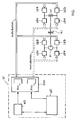
- Fig. 1 shows the essential components of a device for controlling a dual-clutch transmission in a motor vehicle with a first, "normally closed” clutch (K1) and a second, not shown “normally open” clutch (K2).
- a main computer ( ⁇ C), a monitoring unit (WD) and a slave control unit (SSU) are arranged on a common circuit carrier (ST).
- the main computer (.mu.C) is used in particular for regulating the normal operation of the vehicle.
- the monitoring unit (WD) is used essentially for monitoring the main computer (.mu.C), in particular for program sequence control by a question-answer communication between the monitoring unit (WD) and the main computer (.mu.C).
- the circuit carrier (ST) also includes a secondary control unit (SSU), which under certain conditions for triggering an emergency operation of the motor vehicle can be controlled either by the main computer (.mu.C) or by the monitoring unit (WD).
- the auxiliary control unit (SSU) comprises an analog controller (RV1) for controlling a proportional valve (V1) and an analog controller (RM1) for controlling the hydraulic pump (M).
- the dual-clutch transmission has a first hydraulic clutch (K1) and a second hydraulic clutch (K2), not shown.
- the first clutch (K1) is a "normally closed” clutch, which means that it is closed by spring force in the unpressurized state.
- the second clutch (K2) is a "normally open” clutch, that is, it is kept open by spring force in the pressureless state. In normal operation, the two clutches (K1, K2) are controlled by the main computer ( ⁇ C).
- the power-determining output stages (LEN) for the hydraulic pump (M) are energized, and they receive the signals for controlling the hydraulic pump (M) from the analog controller (RM1). Also for controlling the first clutch (K1), the power-determining output stages (LEN) for the proportional valve (V1) are energized, and they receive the signals for controlling the proportional valve (V1) from the analog controller (RV1).
- the auxiliary control unit (SSU) is controlled under certain conditions either by the main computer (.mu.C) or by the monitoring unit (WD). For example, this may be done as a system response of the functional monitoring level or the monitoring software by the host computer ( ⁇ C).
- the emergency operation in particular due to a multiple incorrectly answering a question from the question and answer game between the monitoring unit (WD) and the main computer (.mu.C) by the monitoring unit (WD) happen.
- the first clutch (K1) is closed in the pressureless state for energy saving reasons against the spring force. Therefore, it is necessary to reliably open the first clutch (K1) in emergency operation, particularly by the sub-control unit (SSU).
- SSU sub-control unit
- the emergency operation is shown in Fig. 1 by the solid double line.
- the power-determining output stages (LEN) for controlling the hydraulic pump (M) and the proportional valve (V1) for normal operation are de-energized when the emergency mode is triggered.
- the redundant, power-determining output stages (LES) for controlling the hydraulic pump (M) and the proportional valve (V1) are energized for emergency operation.
- the first clutch (K1) is controlled exclusively by the sub-control unit (SSU) by means of the controller (RV1) and (RM1).
- the power-determining output stages (LEN) for normal operation and power-determining output stages (LES) for emergency operation each have FETs (FETN, FETS) whose gates can be mutually switched by the auxiliary control unit (SSU) each in a conducting or a blocking state.
- the FETs (FETN) are preferably blocking and the FETs (FETs) are turned on. This ensures in particular that in emergency operation, the hydraulic pump (M) and the proportional valve (V1) for controlling the first clutch (K1) receive only signals from the auxiliary control unit (SSU) and not possibly error-prone signals from the possibly defective main computer (.mu.C).
- auxiliary control unit SSU
- the control logic of the analog controller (RM1, RV1) constructed such that when restarting the main computer (.mu.C) by voltage return to the main computer ( ⁇ C), the control of the first clutch (K1) and the hydraulic pump (M) by the analog controller (RM1, RV1) of the auxiliary control unit (SSU) is excluded.
Landscapes
- Engineering & Computer Science (AREA)
- General Engineering & Computer Science (AREA)
- Mechanical Engineering (AREA)
- Hydraulic Clutches, Magnetic Clutches, Fluid Clutches, And Fluid Joints (AREA)
- Control Of Transmission Device (AREA)
Claims (14)
- Dispositif de régulation d'une boîte de vitesses à double embrayage dans un véhicule, comprenant- un ordinateur central (µC) pour la régulation du fonctionnement normal du véhicule qui pilote une unité de commande annexe (SSU) pour le déclenchement d'un fonctionnement d'urgence en présence de premières conditions (B1),- une unité de surveillance (WD) pour la surveillance de l'ordinateur central (µC) qui pilote l'unité de commande annexe (SSU) pour le déclenchement d'un fonctionnement d'urgence en présence de deuxièmes conditions (B2),- un premier embrayage hydraulique (K1) pour les rapports impairs, le premier embrayage (K1) étant fermé par force de ressort dans l'état sans pression,- un deuxième embrayage hydraulique (K2) pour les rapports pairs, le deuxième embrayage (K2) étant ouvert par force de ressort dans l'état sans pression,- une pompe hydraulique (M) qui alimente en pression hydraulique le système hydraulique pour la régulation des embrayages (k1, K2),- une première soupape proportionnelle (V1) pour la régulation de la pression hydraulique sur le premier embrayage (K1),- une deuxième soupape proportionnelle (V2) pour la régulation de la pression hydraulique sur le deuxième embrayage (K2),caractérisé en ce que
l'ordinateur central (µC), l'unité de surveillance (WD) et l'unité de commande annexe (SSU) sont disposés sur un support de circuit (ST) commun, et en ce que l'unité de commande annexe (SSU) comprend un premier régulateur analogique (RV1) pour la régulation de la première soupape proportionnelle (V1) et un deuxième régulateur analogique (RM1) pour la régulation de la pompe hydraulique (M), et en ce que, dans le fonctionnement d'urgence, le premier embrayage (K1) est régulé par l'unité de commande annexe (SSU) au moyen des régulateurs (RV1, RM1). - Dispositif selon la revendication 1, caractérisé en ce que l'ordinateur central (µC) et l'unité de commande annexe (SSU) présentent des alimentations électriques séparées.
- Dispositif selon la revendication 1 ou 2, caractérisé en ce que l'unité de commande annexe (SSU) comprend une partie de régulation analogique pour la régulation de la pression hydraulique dans le système hydraulique au moyen de la vitesse de rotation de la pompe hydraulique (M), une partie logique analogique pour décider si le présent état de fonctionnement correspond au fonctionnement normal ou au fonctionnement d'urgence, et une partie de circuit analogique pour passer de l'état de fonctionnement normal à l'état de fonctionnement d'urgence.
- Dispositif selon une des revendications précédentes, caractérisé en ce que le dispositif comprend des étages finaux (LEN) définissant la puissance pour la commande de la pompe hydraulique (M) et de la soupape proportionnelle (V1) pour le fonctionnement normal qui, lors du déclenchement du fonctionnement d'urgence, peuvent être mis hors tension, et en ce que le dispositif comprend des étages finaux (LES) redondants définissant la puissance pour la commande de la pompe hydraulique (M) et de la première soupape proportionnelle (V1) pour le fonctionnement d'urgence qui peuvent être alimentés en courant lors du déclenchement du fonctionnement d'urgence.
- Dispositif selon la revendication 4, caractérisé en ce que les étages finaux (LEN) et (LES) définissant la puissance comprennent chacun des FET (FETN, FETS) dont les grilles sont commutables par l'unité de commande annexe (SSU) alternativement respectivement dans un état conducteur ou dans un état bloquant.
- Dispositif selon une des revendications précédentes, caractérisé en ce que des grandeurs de guidage sont mémorisées dans l'unité de commande annexe (SSU) et sont fixées par la sélection des composants électroniques de l'unité de commande annexe (SSU), et en ce que la première soupape proportionnelle (V1) et la pompe hydraulique (M) peuvent être régulées par les régulateurs (RV1, RM1) analogiques au moyen de ces grandeurs de guidage.
- Dispositif selon une des revendications précédentes, caractérisé en ce que, dans l'unité de commande annexe (SSU), la logique de commande des régulateurs (RV1, RM1) analogiques est structurée de telle sorte que- lors du redémarrage de l'ordinateur central (µC) par un retour de la tension sur l'ordinateur central (µC), la prise en charge du contrôle du premier embrayage (K1) et de la pompe hydraulique (M) par les régulateurs (RV1, RM1) analogiques de l'unité de commande annexe (SSU) est exclue, et en ce que- lors de chaque autre redémarrage de l'ordinateur central (µC), l'état de fonctionnement précédent de l'unité de commande annexe (SSU) est maintenu.
- Dispositif selon une des revendications précédentes, caractérisé en ce que les premières conditions (B1) de déclenchement d'un fonctionnement d'urgence par l'ordinateur central (µC) est une réaction du système du niveau de surveillance de fonction ou du logiciel de surveillance dans l'ordinateur central (µC).
- Dispositif selon une des revendications 1 à 7, caractérisé en ce que les deuxièmes conditions (B2) de déclenchement d'un fonctionnement d'urgence par l'unité de surveillance (WD) est en particulier la réponse plusieurs fois incorrecte à une question issue du jeu question-réponse entre l'unité de surveillance (WD) et l'ordinateur central (µC).
- Procédé de régulation d'une boîte de vitesses à double embrayage dans un véhicule au moyen d'un dispositif selon une des revendications précédentes,- l'ordinateur central (µC) pilotant, pour le déclenchement d'un fonctionnement d'urgence du véhicule, une unité de commande annexe (SSU) en présence de premières conditions (B1), et- l'unité de surveillance pilotant, pour le déclenchement d'un fonctionnement d'urgence du véhicule, l'unité de commande annexe (SSU) en présence de deuxièmes conditions (B2),caractérisé en ce que
l'unité de commande annexe (SSU), qui comprend le premier régulateur analogique (RV1) pour la régulation de la soupape proportionnelle (V1) et le deuxième régulateur analogique (RM1) pour la régulation de la pompe hydraulique (M), régule dans le fonctionnement d'urgence le premier embrayage (K1) au moyen des régulateurs (RV1, RM1) analogiques. - Procédé selon la revendication 10, caractérisé en ce que, après qu'un fonctionnement d'urgence a été déclenché, la partie logique analogique de l'unité de commande annexe (SSU) décide si le présent état de fonctionnement correspond au fonctionnement normal ou au fonctionnement d'urgence et, en cas de fonctionnement d'urgence, pilote une partie de circuit analogique, et la partie de circuit analogique de l'unité de commande annexe (SSU) commute du fonctionnement normal vers le fonctionnement d'urgence.
- Procédé selon la revendication 10 ou 11, caractérisé en ce que, lors du passage du fonctionnement normal au fonctionnement d'urgence, les étages finaux (LEN) définissant la puissance pour la commande de la pompe hydraulique (M) et de la première soupape proportionnelle (V1) sont mis hors tension par l'unité de commande annexe (SSU), et les étages finaux (LES) redondants définissant la puissance pour la commande de la pompe hydraulique (M) et de la première soupape proportionnelle (V1) sont alimentés en courant par l'unité de commande annexe (SSU).
- Procédé selon la revendication 12, caractérisé en ce que, dans le fonctionnement d'urgence, l'unité de commande annexe (SSU) pilote les FET (FETN, FETS) des étages finaux (LEN) et (LES) définissant la puissance de telle sorte que les grilles des FET (FETN, FETS) sont commutées alternativement respectivement dans un état conducteur ou dans un état bloquant.
- Procédé selon une des revendications précédentes 10 à 13, caractérisé en ce que- lors du redémarrage de l'ordinateur central (µC) par un retour de la tension sur l'ordinateur central (µC), la prise en charge du contrôle du premier embrayage (K1) et de la pompe hydraulique (M) par les régulateurs (RV1, RM1) analogiques de l'unité de commande annexe (SSU) est exclue, et en ce que- lors de chaque autre redémarrage de l'ordinateur central (µC), l'état de fonctionnement précédent de l'unité de commande annexe (SSU) est maintenu.
Applications Claiming Priority (2)
| Application Number | Priority Date | Filing Date | Title |
|---|---|---|---|
| DE102010044280A DE102010044280A1 (de) | 2010-09-02 | 2010-09-02 | Vorrichtung und Verfahren zur Regelung eines Doppelkupplungsgetriebes |
| PCT/DE2011/001640 WO2012037921A2 (fr) | 2010-09-02 | 2011-08-20 | Dispositif et procédé de régulation d'une transmission à double embrayage |
Publications (2)
| Publication Number | Publication Date |
|---|---|
| EP2612059A2 EP2612059A2 (fr) | 2013-07-10 |
| EP2612059B1 true EP2612059B1 (fr) | 2014-04-02 |
Family
ID=45406317
Family Applications (1)
| Application Number | Title | Priority Date | Filing Date |
|---|---|---|---|
| EP11801560.1A Active EP2612059B1 (fr) | 2010-09-02 | 2011-08-20 | Dispositif et procédé de régulation d'une transmission à double embrayage |
Country Status (3)
| Country | Link |
|---|---|
| EP (1) | EP2612059B1 (fr) |
| DE (2) | DE102010044280A1 (fr) |
| WO (1) | WO2012037921A2 (fr) |
Families Citing this family (3)
| Publication number | Priority date | Publication date | Assignee | Title |
|---|---|---|---|---|
| AT516475B1 (de) * | 2014-10-27 | 2017-04-15 | Avl Commercial Driveline & Tractor Eng Gmbh | Hydraulikkreislauf und verfahren zum steuern eines hydraulikkreislaufes |
| DE102016203159A1 (de) * | 2016-02-29 | 2017-08-31 | Robert Bosch Gmbh | Verfahren zum Betrieb eines Brennstoffzellensystems, insbesondere während eines Abstellvorganges des Brennstoffzellensystems |
| CN113357358A (zh) * | 2021-07-07 | 2021-09-07 | 银川威力传动技术股份有限公司 | 新能源汽车多挡变速器的液压控制系统 |
Family Cites Families (7)
| Publication number | Priority date | Publication date | Assignee | Title |
|---|---|---|---|---|
| DE4438714A1 (de) | 1994-10-29 | 1996-05-02 | Bosch Gmbh Robert | Verfahren und Vorrichtung zur Steuerung der Antriebseinheit eines Fahrzeugs |
| JP3991384B2 (ja) * | 1996-07-15 | 2007-10-17 | 株式会社デンソー | 電子制御装置 |
| DE10030085A1 (de) * | 2000-06-19 | 2002-03-07 | Siemens Ag | Elektronische Getriebesteuerung |
| IT1320554B1 (it) * | 2000-07-25 | 2003-12-10 | Magneti Marelli Spa | Dispositivo di controllo di una frizione per autoveicoli. |
| BR0205942A (pt) * | 2001-08-24 | 2003-08-05 | Luk Lamellen & Kupplungsbau | Processo para controle de uma engrenagem de mudança automática, sistema de segurança eletrônico, bem como pino de encaixe intermediário |
| EP1673667B1 (fr) * | 2003-10-08 | 2009-07-29 | Continental Teves AG & Co. oHG | Systeme de microprocesseur integre pour regulations critiques en termes de securite |
| DE102007063212B4 (de) * | 2007-12-20 | 2010-02-04 | Getrag Getriebe- Und Zahnradfabrik Hermann Hagenmeyer Gmbh & Cie Kg | Aktuatoranordnung für einen Kraftfahrzeugantriebsstrang sowie Verfahren zum Betreiben einer Aktuatoranordnung |
-
2010
- 2010-09-02 DE DE102010044280A patent/DE102010044280A1/de not_active Withdrawn
-
2011
- 2011-08-20 DE DE112011102565T patent/DE112011102565A5/de not_active Withdrawn
- 2011-08-20 EP EP11801560.1A patent/EP2612059B1/fr active Active
- 2011-08-20 WO PCT/DE2011/001640 patent/WO2012037921A2/fr not_active Ceased
Also Published As
| Publication number | Publication date |
|---|---|
| WO2012037921A2 (fr) | 2012-03-29 |
| EP2612059A2 (fr) | 2013-07-10 |
| DE112011102565A5 (de) | 2013-05-08 |
| DE102010044280A1 (de) | 2012-03-08 |
| WO2012037921A3 (fr) | 2012-06-07 |
Similar Documents
| Publication | Publication Date | Title |
|---|---|---|
| EP2676200B1 (fr) | Circuit à semi-conducteurs et procédé conçu comme concept de sécurité utilisés dans un véhicule automobile | |
| EP1219489B1 (fr) | Système et procédé de commande et/ou surveillance d'un ensemble comportant au moins deux contrôleurs | |
| DE102008061564A1 (de) | Kupplungsaktor und Verfahren zu dessen Steuerung | |
| DE10064673B4 (de) | Fehlertolerante elektromechanische Stelleinrichtung | |
| EP3661819B1 (fr) | Système de commande pour véhicule automobile, véhicule automobile, procédé de commande d'un véhicule automobile, produit programme informatique et support lisible par ordinateur | |
| DE10351968A1 (de) | Schaltsystem für ein Fahrzeug | |
| EP2513455B1 (fr) | Concept de surveillance destiné à un appareil de commande | |
| EP2739883B1 (fr) | Procédé et appareil de commande d'un élément d'une chaîne cinématique | |
| DE10236080A1 (de) | Verfahren und Vorrichtung zur Steuerung von Betriebsabläufen, insbesondere in einem Fahrzeug | |
| EP1989470B1 (fr) | Concept de sécurité pour un dispositif de positionnement à engrenage | |
| DE102014211355A1 (de) | Steuergerät | |
| WO2011026457A1 (fr) | Actionneur d'embrayage | |
| DE102011017741B4 (de) | Verfahren zum Überwachen eines Schaltablaufs eines automatischen Getriebes | |
| DE102007021871A1 (de) | Verfahren und System zum Überwachen des Betriebs eines Antriebsstrangs eines Fahrzeugs | |
| WO2012037921A2 (fr) | Dispositif et procédé de régulation d'une transmission à double embrayage | |
| DE102011087063A1 (de) | Kontrollrechnersystem und Verfahren zur beschleunigten Initialisierung einzelner Module | |
| EP2676052B1 (fr) | Procédé et dispositif de régulation d'une boîte de vitesses à double embrayage pour parvenir à un état de sécurité | |
| DE102007046731B4 (de) | Verfahren zur Ansteuerung eines Aktuators in einem Kraftfahrzeug | |
| DE102019132428B4 (de) | Funktionsorientierte Elektronik-Architektur | |
| DE102011100982A1 (de) | Anlage mit einem Steuersystem zur Steuerung von Anlagefunktionen | |
| DE102011011224A1 (de) | Steuergeräteanordnung | |
| WO2016066515A1 (fr) | Circuit hydraulique et procédé de commande d'un circuit hydraulique | |
| DE102007026326B4 (de) | Sicherheitskonzept für einen Getriebesteller | |
| DE102009000251A1 (de) | Getriebesteuerungseinrichtung | |
| WO2025103650A1 (fr) | Procédé de fonctionnement d'un ensemble actionneur, ensemble actionneur et véhicule automobile |
Legal Events
| Date | Code | Title | Description |
|---|---|---|---|
| PUAI | Public reference made under article 153(3) epc to a published international application that has entered the european phase |
Free format text: ORIGINAL CODE: 0009012 |
|
| 17P | Request for examination filed |
Effective date: 20130208 |
|
| AK | Designated contracting states |
Kind code of ref document: A2 Designated state(s): AL AT BE BG CH CY CZ DE DK EE ES FI FR GB GR HR HU IE IS IT LI LT LU LV MC MK MT NL NO PL PT RO RS SE SI SK SM TR |
|
| REG | Reference to a national code |
Ref country code: DE Ref legal event code: R079 Ref document number: 502011002635 Country of ref document: DE Free format text: PREVIOUS MAIN CLASS: F16H0061140000 Ipc: F16H0061120000 |
|
| DAX | Request for extension of the european patent (deleted) | ||
| GRAP | Despatch of communication of intention to grant a patent |
Free format text: ORIGINAL CODE: EPIDOSNIGR1 |
|
| RIC1 | Information provided on ipc code assigned before grant |
Ipc: F16H 61/688 20060101ALI20131202BHEP Ipc: F16H 61/12 20100101AFI20131202BHEP |
|
| INTG | Intention to grant announced |
Effective date: 20140108 |
|
| GRAS | Grant fee paid |
Free format text: ORIGINAL CODE: EPIDOSNIGR3 |
|
| GRAA | (expected) grant |
Free format text: ORIGINAL CODE: 0009210 |
|
| AK | Designated contracting states |
Kind code of ref document: B1 Designated state(s): AL AT BE BG CH CY CZ DE DK EE ES FI FR GB GR HR HU IE IS IT LI LT LU LV MC MK MT NL NO PL PT RO RS SE SI SK SM TR |
|
| REG | Reference to a national code |
Ref country code: GB Ref legal event code: FG4D Free format text: NOT ENGLISH |
|
| REG | Reference to a national code |
Ref country code: AT Ref legal event code: REF Ref document number: 660332 Country of ref document: AT Kind code of ref document: T Effective date: 20140415 Ref country code: CH Ref legal event code: EP |
|
| REG | Reference to a national code |
Ref country code: IE Ref legal event code: FG4D Free format text: LANGUAGE OF EP DOCUMENT: GERMAN |
|
| REG | Reference to a national code |
Ref country code: DE Ref legal event code: R096 Ref document number: 502011002635 Country of ref document: DE Effective date: 20140515 |
|
| REG | Reference to a national code |
Ref country code: NL Ref legal event code: VDEP Effective date: 20140402 |
|
| REG | Reference to a national code |
Ref country code: LT Ref legal event code: MG4D |
|
| PG25 | Lapsed in a contracting state [announced via postgrant information from national office to epo] |
Ref country code: BG Free format text: LAPSE BECAUSE OF FAILURE TO SUBMIT A TRANSLATION OF THE DESCRIPTION OR TO PAY THE FEE WITHIN THE PRESCRIBED TIME-LIMIT Effective date: 20140702 Ref country code: NO Free format text: LAPSE BECAUSE OF FAILURE TO SUBMIT A TRANSLATION OF THE DESCRIPTION OR TO PAY THE FEE WITHIN THE PRESCRIBED TIME-LIMIT Effective date: 20140702 Ref country code: CZ Free format text: LAPSE BECAUSE OF FAILURE TO SUBMIT A TRANSLATION OF THE DESCRIPTION OR TO PAY THE FEE WITHIN THE PRESCRIBED TIME-LIMIT Effective date: 20140402 Ref country code: NL Free format text: LAPSE BECAUSE OF FAILURE TO SUBMIT A TRANSLATION OF THE DESCRIPTION OR TO PAY THE FEE WITHIN THE PRESCRIBED TIME-LIMIT Effective date: 20140402 Ref country code: CY Free format text: LAPSE BECAUSE OF FAILURE TO SUBMIT A TRANSLATION OF THE DESCRIPTION OR TO PAY THE FEE WITHIN THE PRESCRIBED TIME-LIMIT Effective date: 20140402 Ref country code: GR Free format text: LAPSE BECAUSE OF FAILURE TO SUBMIT A TRANSLATION OF THE DESCRIPTION OR TO PAY THE FEE WITHIN THE PRESCRIBED TIME-LIMIT Effective date: 20140703 Ref country code: IS Free format text: LAPSE BECAUSE OF FAILURE TO SUBMIT A TRANSLATION OF THE DESCRIPTION OR TO PAY THE FEE WITHIN THE PRESCRIBED TIME-LIMIT Effective date: 20140802 Ref country code: FI Free format text: LAPSE BECAUSE OF FAILURE TO SUBMIT A TRANSLATION OF THE DESCRIPTION OR TO PAY THE FEE WITHIN THE PRESCRIBED TIME-LIMIT Effective date: 20140402 Ref country code: LT Free format text: LAPSE BECAUSE OF FAILURE TO SUBMIT A TRANSLATION OF THE DESCRIPTION OR TO PAY THE FEE WITHIN THE PRESCRIBED TIME-LIMIT Effective date: 20140402 |
|
| PG25 | Lapsed in a contracting state [announced via postgrant information from national office to epo] |
Ref country code: PL Free format text: LAPSE BECAUSE OF FAILURE TO SUBMIT A TRANSLATION OF THE DESCRIPTION OR TO PAY THE FEE WITHIN THE PRESCRIBED TIME-LIMIT Effective date: 20140402 Ref country code: SE Free format text: LAPSE BECAUSE OF FAILURE TO SUBMIT A TRANSLATION OF THE DESCRIPTION OR TO PAY THE FEE WITHIN THE PRESCRIBED TIME-LIMIT Effective date: 20140402 Ref country code: LV Free format text: LAPSE BECAUSE OF FAILURE TO SUBMIT A TRANSLATION OF THE DESCRIPTION OR TO PAY THE FEE WITHIN THE PRESCRIBED TIME-LIMIT Effective date: 20140402 Ref country code: ES Free format text: LAPSE BECAUSE OF FAILURE TO SUBMIT A TRANSLATION OF THE DESCRIPTION OR TO PAY THE FEE WITHIN THE PRESCRIBED TIME-LIMIT Effective date: 20140402 Ref country code: HR Free format text: LAPSE BECAUSE OF FAILURE TO SUBMIT A TRANSLATION OF THE DESCRIPTION OR TO PAY THE FEE WITHIN THE PRESCRIBED TIME-LIMIT Effective date: 20140402 Ref country code: RS Free format text: LAPSE BECAUSE OF FAILURE TO SUBMIT A TRANSLATION OF THE DESCRIPTION OR TO PAY THE FEE WITHIN THE PRESCRIBED TIME-LIMIT Effective date: 20140402 |
|
| PG25 | Lapsed in a contracting state [announced via postgrant information from national office to epo] |
Ref country code: PT Free format text: LAPSE BECAUSE OF FAILURE TO SUBMIT A TRANSLATION OF THE DESCRIPTION OR TO PAY THE FEE WITHIN THE PRESCRIBED TIME-LIMIT Effective date: 20140804 |
|
| REG | Reference to a national code |
Ref country code: DE Ref legal event code: R097 Ref document number: 502011002635 Country of ref document: DE |
|
| PG25 | Lapsed in a contracting state [announced via postgrant information from national office to epo] |
Ref country code: DK Free format text: LAPSE BECAUSE OF FAILURE TO SUBMIT A TRANSLATION OF THE DESCRIPTION OR TO PAY THE FEE WITHIN THE PRESCRIBED TIME-LIMIT Effective date: 20140402 Ref country code: SK Free format text: LAPSE BECAUSE OF FAILURE TO SUBMIT A TRANSLATION OF THE DESCRIPTION OR TO PAY THE FEE WITHIN THE PRESCRIBED TIME-LIMIT Effective date: 20140402 Ref country code: RO Free format text: LAPSE BECAUSE OF FAILURE TO SUBMIT A TRANSLATION OF THE DESCRIPTION OR TO PAY THE FEE WITHIN THE PRESCRIBED TIME-LIMIT Effective date: 20140402 Ref country code: EE Free format text: LAPSE BECAUSE OF FAILURE TO SUBMIT A TRANSLATION OF THE DESCRIPTION OR TO PAY THE FEE WITHIN THE PRESCRIBED TIME-LIMIT Effective date: 20140402 |
|
| PLBE | No opposition filed within time limit |
Free format text: ORIGINAL CODE: 0009261 |
|
| STAA | Information on the status of an ep patent application or granted ep patent |
Free format text: STATUS: NO OPPOSITION FILED WITHIN TIME LIMIT |
|
| 26N | No opposition filed |
Effective date: 20150106 |
|
| PG25 | Lapsed in a contracting state [announced via postgrant information from national office to epo] |
Ref country code: MC Free format text: LAPSE BECAUSE OF FAILURE TO SUBMIT A TRANSLATION OF THE DESCRIPTION OR TO PAY THE FEE WITHIN THE PRESCRIBED TIME-LIMIT Effective date: 20140402 Ref country code: LU Free format text: LAPSE BECAUSE OF FAILURE TO SUBMIT A TRANSLATION OF THE DESCRIPTION OR TO PAY THE FEE WITHIN THE PRESCRIBED TIME-LIMIT Effective date: 20140820 Ref country code: IT Free format text: LAPSE BECAUSE OF FAILURE TO SUBMIT A TRANSLATION OF THE DESCRIPTION OR TO PAY THE FEE WITHIN THE PRESCRIBED TIME-LIMIT Effective date: 20140402 |
|
| REG | Reference to a national code |
Ref country code: CH Ref legal event code: PL |
|
| REG | Reference to a national code |
Ref country code: DE Ref legal event code: R097 Ref document number: 502011002635 Country of ref document: DE Effective date: 20150106 |
|
| PG25 | Lapsed in a contracting state [announced via postgrant information from national office to epo] |
Ref country code: CH Free format text: LAPSE BECAUSE OF NON-PAYMENT OF DUE FEES Effective date: 20140831 Ref country code: BE Free format text: LAPSE BECAUSE OF NON-PAYMENT OF DUE FEES Effective date: 20140831 Ref country code: LI Free format text: LAPSE BECAUSE OF NON-PAYMENT OF DUE FEES Effective date: 20140831 |
|
| REG | Reference to a national code |
Ref country code: IE Ref legal event code: MM4A |
|
| PG25 | Lapsed in a contracting state [announced via postgrant information from national office to epo] |
Ref country code: RS Free format text: LAPSE BECAUSE OF FAILURE TO SUBMIT A TRANSLATION OF THE DESCRIPTION OR TO PAY THE FEE WITHIN THE PRESCRIBED TIME-LIMIT Effective date: 20141119 |
|
| PG25 | Lapsed in a contracting state [announced via postgrant information from national office to epo] |
Ref country code: SI Free format text: LAPSE BECAUSE OF FAILURE TO SUBMIT A TRANSLATION OF THE DESCRIPTION OR TO PAY THE FEE WITHIN THE PRESCRIBED TIME-LIMIT Effective date: 20140402 |
|
| PG25 | Lapsed in a contracting state [announced via postgrant information from national office to epo] |
Ref country code: IE Free format text: LAPSE BECAUSE OF NON-PAYMENT OF DUE FEES Effective date: 20140820 |
|
| GBPC | Gb: european patent ceased through non-payment of renewal fee |
Effective date: 20150820 |
|
| PG25 | Lapsed in a contracting state [announced via postgrant information from national office to epo] |
Ref country code: SM Free format text: LAPSE BECAUSE OF FAILURE TO SUBMIT A TRANSLATION OF THE DESCRIPTION OR TO PAY THE FEE WITHIN THE PRESCRIBED TIME-LIMIT Effective date: 20140402 |
|
| PG25 | Lapsed in a contracting state [announced via postgrant information from national office to epo] |
Ref country code: MT Free format text: LAPSE BECAUSE OF FAILURE TO SUBMIT A TRANSLATION OF THE DESCRIPTION OR TO PAY THE FEE WITHIN THE PRESCRIBED TIME-LIMIT Effective date: 20140402 |
|
| PG25 | Lapsed in a contracting state [announced via postgrant information from national office to epo] |
Ref country code: HU Free format text: LAPSE BECAUSE OF FAILURE TO SUBMIT A TRANSLATION OF THE DESCRIPTION OR TO PAY THE FEE WITHIN THE PRESCRIBED TIME-LIMIT; INVALID AB INITIO Effective date: 20110820 Ref country code: GB Free format text: LAPSE BECAUSE OF NON-PAYMENT OF DUE FEES Effective date: 20150820 |
|
| REG | Reference to a national code |
Ref country code: FR Ref legal event code: PLFP Year of fee payment: 6 |
|
| REG | Reference to a national code |
Ref country code: FR Ref legal event code: PLFP Year of fee payment: 7 |
|
| PG25 | Lapsed in a contracting state [announced via postgrant information from national office to epo] |
Ref country code: TR Free format text: LAPSE BECAUSE OF FAILURE TO SUBMIT A TRANSLATION OF THE DESCRIPTION OR TO PAY THE FEE WITHIN THE PRESCRIBED TIME-LIMIT Effective date: 20140402 |
|
| REG | Reference to a national code |
Ref country code: AT Ref legal event code: MM01 Ref document number: 660332 Country of ref document: AT Kind code of ref document: T Effective date: 20160820 |
|
| PG25 | Lapsed in a contracting state [announced via postgrant information from national office to epo] |
Ref country code: AT Free format text: LAPSE BECAUSE OF NON-PAYMENT OF DUE FEES Effective date: 20160820 |
|
| PG25 | Lapsed in a contracting state [announced via postgrant information from national office to epo] |
Ref country code: MK Free format text: LAPSE BECAUSE OF FAILURE TO SUBMIT A TRANSLATION OF THE DESCRIPTION OR TO PAY THE FEE WITHIN THE PRESCRIBED TIME-LIMIT Effective date: 20140402 |
|
| REG | Reference to a national code |
Ref country code: FR Ref legal event code: PLFP Year of fee payment: 8 |
|
| PG25 | Lapsed in a contracting state [announced via postgrant information from national office to epo] |
Ref country code: AL Free format text: LAPSE BECAUSE OF FAILURE TO SUBMIT A TRANSLATION OF THE DESCRIPTION OR TO PAY THE FEE WITHIN THE PRESCRIBED TIME-LIMIT Effective date: 20140402 |
|
| REG | Reference to a national code |
Ref country code: DE Ref legal event code: R081 Ref document number: 502011002635 Country of ref document: DE Owner name: VITESCO TECHNOLOGIES GERMANY GMBH, DE Free format text: FORMER OWNER: CONTI TEMIC MICROELECTRONIC GMBH, 90411 NUERNBERG, DE |
|
| REG | Reference to a national code |
Ref country code: DE Ref legal event code: R084 Ref document number: 502011002635 Country of ref document: DE |
|
| REG | Reference to a national code |
Ref country code: DE Ref legal event code: R081 Ref document number: 502011002635 Country of ref document: DE Owner name: SCHAEFFLER TECHNOLOGIES AG & CO. KG, DE Free format text: FORMER OWNER: VITESCO TECHNOLOGIES GERMANY GMBH, 30165 HANNOVER, DE Ref country code: DE Ref legal event code: R081 Ref document number: 502011002635 Country of ref document: DE Owner name: VITESCO TECHNOLOGIES GERMANY GMBH, DE Free format text: FORMER OWNER: VITESCO TECHNOLOGIES GERMANY GMBH, 30165 HANNOVER, DE |
|
| P01 | Opt-out of the competence of the unified patent court (upc) registered |
Effective date: 20230530 |
|
| REG | Reference to a national code |
Ref country code: DE Ref legal event code: R081 Ref document number: 502011002635 Country of ref document: DE Owner name: SCHAEFFLER TECHNOLOGIES AG & CO. KG, DE Free format text: FORMER OWNER: VITESCO TECHNOLOGIES GERMANY GMBH, REGENSBURG, DE |
|
| PGFP | Annual fee paid to national office [announced via postgrant information from national office to epo] |
Ref country code: DE Payment date: 20250831 Year of fee payment: 15 |
|
| PGFP | Annual fee paid to national office [announced via postgrant information from national office to epo] |
Ref country code: FR Payment date: 20250829 Year of fee payment: 15 |