EP2612841A1 - Lagunage capable de fonctionner en continu pendent des périodes à températures bases - Google Patents
Lagunage capable de fonctionner en continu pendent des périodes à températures bases Download PDFInfo
- Publication number
- EP2612841A1 EP2612841A1 EP20120171182 EP12171182A EP2612841A1 EP 2612841 A1 EP2612841 A1 EP 2612841A1 EP 20120171182 EP20120171182 EP 20120171182 EP 12171182 A EP12171182 A EP 12171182A EP 2612841 A1 EP2612841 A1 EP 2612841A1
- Authority
- EP
- European Patent Office
- Prior art keywords
- water
- pipe
- substrates
- constructed wetland
- water outlet
- Prior art date
- Legal status (The legal status is an assumption and is not a legal conclusion. Google has not performed a legal analysis and makes no representation as to the accuracy of the status listed.)
- Granted
Links
- 238000004065 wastewater treatment Methods 0.000 title claims abstract description 20
- XLYOFNOQVPJJNP-UHFFFAOYSA-N water Substances O XLYOFNOQVPJJNP-UHFFFAOYSA-N 0.000 claims abstract description 245
- 239000000758 substrate Substances 0.000 claims abstract description 57
- 238000004321 preservation Methods 0.000 claims abstract description 17
- 230000020169 heat generation Effects 0.000 claims abstract description 10
- 238000009423 ventilation Methods 0.000 claims abstract description 8
- 230000004888 barrier function Effects 0.000 claims abstract description 4
- 239000000126 substance Substances 0.000 claims abstract description 4
- 235000019738 Limestone Nutrition 0.000 claims description 9
- 239000006028 limestone Substances 0.000 claims description 9
- 239000002245 particle Substances 0.000 claims description 7
- OKTJSMMVPCPJKN-UHFFFAOYSA-N Carbon Chemical compound [C] OKTJSMMVPCPJKN-UHFFFAOYSA-N 0.000 claims description 3
- 229910021536 Zeolite Inorganic materials 0.000 claims description 3
- 229910052799 carbon Inorganic materials 0.000 claims description 3
- HNPSIPDUKPIQMN-UHFFFAOYSA-N dioxosilane;oxo(oxoalumanyloxy)alumane Chemical compound O=[Si]=O.O=[Al]O[Al]=O HNPSIPDUKPIQMN-UHFFFAOYSA-N 0.000 claims description 3
- -1 gravel Substances 0.000 claims description 3
- 239000002893 slag Substances 0.000 claims description 3
- 239000010457 zeolite Substances 0.000 claims description 3
- 238000005202 decontamination Methods 0.000 claims description 2
- 230000003588 decontaminative effect Effects 0.000 claims description 2
- 239000000203 mixture Substances 0.000 description 9
- 235000005324 Typha latifolia Nutrition 0.000 description 7
- 244000118869 coast club rush Species 0.000 description 7
- 230000000694 effects Effects 0.000 description 7
- 239000010802 sludge Substances 0.000 description 6
- QVGXLLKOCUKJST-UHFFFAOYSA-N atomic oxygen Chemical compound [O] QVGXLLKOCUKJST-UHFFFAOYSA-N 0.000 description 5
- 239000001301 oxygen Substances 0.000 description 5
- 229910052760 oxygen Inorganic materials 0.000 description 5
- 239000007789 gas Substances 0.000 description 4
- 244000005700 microbiome Species 0.000 description 3
- IJGRMHOSHXDMSA-UHFFFAOYSA-N Atomic nitrogen Chemical compound N#N IJGRMHOSHXDMSA-UHFFFAOYSA-N 0.000 description 2
- 230000008901 benefit Effects 0.000 description 2
- VNWKTOKETHGBQD-UHFFFAOYSA-N methane Chemical compound C VNWKTOKETHGBQD-UHFFFAOYSA-N 0.000 description 2
- 239000003895 organic fertilizer Substances 0.000 description 2
- 230000001131 transforming effect Effects 0.000 description 2
- 241000196324 Embryophyta Species 0.000 description 1
- OAICVXFJPJFONN-UHFFFAOYSA-N Phosphorus Chemical compound [P] OAICVXFJPJFONN-UHFFFAOYSA-N 0.000 description 1
- 238000010564 aerobic fermentation Methods 0.000 description 1
- 230000000903 blocking effect Effects 0.000 description 1
- 239000000356 contaminant Substances 0.000 description 1
- 238000011109 contamination Methods 0.000 description 1
- 238000000855 fermentation Methods 0.000 description 1
- 238000007710 freezing Methods 0.000 description 1
- 230000008014 freezing Effects 0.000 description 1
- 239000003673 groundwater Substances 0.000 description 1
- 239000011159 matrix material Substances 0.000 description 1
- 230000002503 metabolic effect Effects 0.000 description 1
- 238000000034 method Methods 0.000 description 1
- 229910052757 nitrogen Inorganic materials 0.000 description 1
- 230000006641 stabilisation Effects 0.000 description 1
- 238000011105 stabilization Methods 0.000 description 1
- 230000009466 transformation Effects 0.000 description 1
- 238000005406 washing Methods 0.000 description 1
- 239000002699 waste material Substances 0.000 description 1
- 239000002351 wastewater Substances 0.000 description 1
Images
Classifications
-
- C—CHEMISTRY; METALLURGY
- C02—TREATMENT OF WATER, WASTE WATER, SEWAGE, OR SLUDGE
- C02F—TREATMENT OF WATER, WASTE WATER, SEWAGE, OR SLUDGE
- C02F3/00—Biological treatment of water, waste water, or sewage
- C02F3/32—Biological treatment of water, waste water, or sewage characterised by the animals or plants used, e.g. algae
- C02F3/327—Biological treatment of water, waste water, or sewage characterised by the animals or plants used, e.g. algae characterised by animals and plants
-
- C—CHEMISTRY; METALLURGY
- C02—TREATMENT OF WATER, WASTE WATER, SEWAGE, OR SLUDGE
- C02F—TREATMENT OF WATER, WASTE WATER, SEWAGE, OR SLUDGE
- C02F2301/00—General aspects of water treatment
- C02F2301/04—Flow arrangements
-
- C—CHEMISTRY; METALLURGY
- C02—TREATMENT OF WATER, WASTE WATER, SEWAGE, OR SLUDGE
- C02F—TREATMENT OF WATER, WASTE WATER, SEWAGE, OR SLUDGE
- C02F3/00—Biological treatment of water, waste water, or sewage
- C02F3/02—Aerobic processes
- C02F3/06—Aerobic processes using submerged filters
-
- Y—GENERAL TAGGING OF NEW TECHNOLOGICAL DEVELOPMENTS; GENERAL TAGGING OF CROSS-SECTIONAL TECHNOLOGIES SPANNING OVER SEVERAL SECTIONS OF THE IPC; TECHNICAL SUBJECTS COVERED BY FORMER USPC CROSS-REFERENCE ART COLLECTIONS [XRACs] AND DIGESTS
- Y02—TECHNOLOGIES OR APPLICATIONS FOR MITIGATION OR ADAPTATION AGAINST CLIMATE CHANGE
- Y02W—CLIMATE CHANGE MITIGATION TECHNOLOGIES RELATED TO WASTEWATER TREATMENT OR WASTE MANAGEMENT
- Y02W10/00—Technologies for wastewater treatment
- Y02W10/10—Biological treatment of water, waste water, or sewage
Definitions
- the present invention relates to a heat preservation and temperature increasing equipment, and in particular, to a constructed wetland wastewater treatment equipment under low temperature for continuous operation.
- An object of the present invention is to provide a constructed wetland wastewater treatment equipment under low temperature for continuous operation to improve a high removal rate of nitrogen and phosphor, stabilization for a treatment effect and recycle of wastes. Further, the constructed wetland wastewater treatment equipment has a flow transformable function to ensure the constructed wetland to operate continuously and stably.
- the constructed wetland wastewater treatment equipment under low temperature for continuous operation mainly comprises:
- the substrates of the constructed wetland wastewater treatment equipment are a combination of one or more of zeolite, gravel, limestone, slag, active carbon.
- An upper section of substrates connected with the water inlet pipe is 10%-20% in length of a total length of the three-section substrates.
- a middle section of substrates is 70%-85% in length of the total length.
- a lower section of substrates connected with the water outlet pipe is 5%-10% in length of the total length.
- the height of the substrates is 1.6-1.8m, and the height of the bed is 2.2-2.5m.
- particle diameters of the upper section of substrates connected with the water inlet pipe and the lower section of substrates connected with the water outlet pipe are both 16-32 mm, and a particle diameter of the middle section of substrates is 8-16 mm.
- the water distributing pipe and the water inlet pipe are connected to the water head tank by respective water inlet valves.
- the water collecting pipe and the water outlet pipe are provided with respective main control valves and respective sub-control valves at different heights.
- Each of the water collecting pipe and the water outlet pipe is provided with three sub-control valves which are respectively mounted at a position higher than the height of the bed of the constructed wetland, in the middle of the substrates, and at the bottom of the bed of the constructed wetland.
- the water distributing pipe and the water collecting pipe are both made of a PVC pipe with diameters from 100mm to 200mm.
- the water distributing pipe uniformly distributes the water, apertures are arranged on the water distributing pipe at an interval of 10-20cm and a diameter of each of the apertures is 1-3cm.
- the water collecting pipe is provided with water collecting apertures corresponding to the middle section of substrates.
- the water collecting apertures are arranged on the water collecting pipe at an interval of 5-10cm and a diameter of each of the water collecting apertures is 1-3cm.
- the upper layer of the constructed wetland is planted with emerged plants having strong decontamination.
- a leakage-proof layer is coated at the bottom inside of the double wall.
- the flow transformable wetland can mutually transform the horizontal flow wetland and the vertical flow wetland therebetween by adjusting distributing pipes based on the change of the ambient temperature. This overcomes disadvantages that dissolved oxygen of incoming water is low in the horizontal flow wetland in summer and a thermal loss is much in the vertical flow wetland in winter. Thereby, the operating mode of the wetland can be flexibly adjusted in winter.
- the influence of the ambient temperature on the wetland is relieved by forming the heat preservation layer composed of the ice layer and the air layer, and the wetland can achieve a continuous heat preservation and temperature increase by a heat generated by metabolization of microorganism in the double wall, thereby ensuring the constructed wetland to continuously and stably operate under the low temperature.
- the flow transformable wetland has advantages of mutual transformation between the vertical flow wetland and the horizontal flow wetland, washing a matrix with water flowing in different directions, having a high organic substance decomposing effect and so on.
- the present invention can be applied widely in large-scale, middle-scale and small-scale constructed wetlands to preserve temperature in winter. Therefore, the present invention has features of operating without pollution, easily operating, saving costs, having a low operating cost, achieving a good heat preservation effect, circulating resources, having a strong processing ability, stably operating and so on.
- the present invention effectively combines the horizontal flow wetland and the vertical flow wetland so that the operating mode of the wetland can be flexibly adjusted in winter.
- the water temperature in the wetland is substantially not affected by the ambient temperature by using the ice layer and an insulating air layer in a heat preservation manner insulating from the heat generated by metabolization of microorganism in the double wall, thereby ensuring the constructed wetland to endure the entire winter.
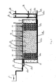
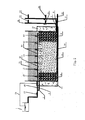
- FIGS 1 and 2 are schematically detailed structural views according to the present invention.
- a water head tank 1 discharges wastewater to be treated into a constructed wetland respectively by an upper water inlet pipe 2 and a top water distributing pipe 15.
- Substrates with different particle diameters are vertically filled and parallel to each other in the constructed wetland.
- the inside of the constructed wetland is divided into a left section 4, a middle section 5 and a right section 6.
- the substrates of the present invention may be zeolite, gravel, limestone, slag, active carbon and the like, and a combination of various substrates.
- the limestone is described simply by way of an example in the following context. Specifically, particle diameters of limestone substrates in the left and right sections 4, 6 are both 16-32 mm. A particle diameter of limestone substrate in the middle section 5 is 8-16 mm.
- the constructed wetland comprises the water inlet pipe 2 and the water distributing pipe 15, and a water outlet pipe 9 and a water collecting pipe 16 which are respectively controlled to introduce and discharge water by respective water inlet control valves and water outlet control valves.
- a top water inlet pipe 13 of the water head tank 1 and the left section 4 of the constructed wetland are connected with the water inlet pipe 2 by an upper water inlet valve 3, while the top water inlet pipe 13 is also connected with the water distributing pipe 15 by a top water inlet valve 14.
- the water outlet pipe 9 is mounted in a lower portion of the right section 6 on the other side of the constructed wetland.
- a main control valve 7and sub-control valves 8, 10, 11 are mounted on the water outlet pipe 9.
- the water collecting pipe 16 is mounted in a bottom layer of the constructed wetland.
- a main control valve 17 and sub-control valves 18, 19, 20 are mounted on the water collecting pipe 16.
- a water outlet of the water outlet pipe 9 and the water collecting pipe 16 is higher than a height of the bed of the constructed wetland.
- the highest sub-control valves 10 (19) of the sub-control valves 8, 10, 11 (18, 19, 20) must be located at a higher position than the height of the bed of the constructed wetland.
- the lowest sub-control valves 8 (18) of the sub-control valves 8, 10, 11 (18, 19, 20) are located at the bottom of the constructed wetland.
- the middle sub-control valves 11 (20) of the sub-control valves 8, 10, 11 (18, 19, 20) are located at a middle position of the limestone substrates.
- the sub-control valves are respectively designed to be located to have distances of 2.4m (the sub-control valves 10, 19), 1.3m (the sub-control valves 11, 20), 0.1m (the sub-control valves 8, 18) from the bottom layer of the bed in order to adjust water levels of the wetland cells, when the height of the substrates in the constructed wetland is 1.6-1.8m and the height of the bed is 2.2-2.5m.
- a barrier at periphery of the constructed wetland has a structure of a double wall 23 in which a uniformly mixed mixture of dejecta, bulrush and activated sludge is filled.
- a leakage-proof layer lies at a bottom inside of the double wall 23 to prevent a percolate generated by ferment of the mixture 23 of dejecta, bulrush and activated sludge from infiltrating underground to pollute ground water.
- the constructed wetland wastewater treatment equipment according to the present invention operates in the winter as described below.
- a top of the double wall 23 is opened as shown in FIG. 1 .
- the bulrush, dejecta and activated sludge are crushed by a crusher and then uniformly mixed.
- a water content of the mixture of bulrush, dejecta and activated sludge is adjusted by adding the water (this is known technology and not emphases of the present invention and thus is not described in detail).
- a height of the mixture is slightly higher than the height of the limestone substrates in the constructed wetland.
- the mixture leaves a height of 0.2 m at intervals of 1-2 m to form ventilation slots which have the same height as that of the mixture.
- the bulrush with a thickness of 0.1-0.2 m covers over the mixture to achieve a heat preservation effect.
- the main control valve 7 of the upper water inlet valve3 and the water outlet pipe 9 is closed and the top water inlet valve 14 is opened when the constructed wetland is a vertical down flow wetland.
- the top water inlet pipe 13 begins to uniformly distribute the water through the water distributing pipe 15. Meanwhile, the main control valve 17 and the sub-control valve 19 of the water collecting pipe16 at the bottom layer of the constructed wetland are opened so that the water level rises to 2.4m.
- the water collecting pipe 16 discharges the water (the water collecting pipe 16 of the present invention can be opened by a water aperture only at a position corresponding to the substrates in the middle section to enhance fluidity of the water flow in the constructed wetland) after water in the upper water level is froze (generally froze with a thickness of 0.4-0.6m).
- the sub-control valve 19 is then closed and the sub-control valve 18 is opened to rapidly lower the water level.
- the sub-control valve 18 is closed and the water outlet valve 20 is opened to discharge the water to the operating water level, thereby forming a heat preservation layer composed of an ice layer 21 and an air layer 22.
- top ventilation pipes 12 are opened to ensure concentration of dissolved oxygen under the ice.
- the top water inlet valve 14 and the main control valve 17 of the water collecting pipe 16 are closed, and the upper water inlet valve 3 and the main control valve 7 and the sub-control valve 10 of the water outlet pipe 9 are opened, when the constructed wetland is a horizontal flow.
- the water begins to enter the water inlet pipe 2 so that the water level rises to 2.4m.
- the water outlet pipe 9 discharges the water, the sub-control valve 10 is closed and the sub-control valve 8 is opened so as to rapidly lower the water level, after the upper water level is froze to 0.4-0.6m.
- the sub-control valve 8 When the operating water level of the wetland is reduced to 2.0m, the sub-control valve 8 is closed and the water outlet valve 11 is opened to discharge the water to the operating water level, thereby forming the heat preservation layer composed of the ice layer 21 and the air layer 22. At that time, the top ventilation pipes 12 are opened to ensure concentration of dissolved oxygen under the ice.
- the vertical flow and the horizontal flow can be mutually transformed.
- the transforming period depends on specific conditions. For example, the vertical flow operates in the early winter and the horizontal flow operates in the severe winter.
- the equipment of the present invention is started in the late autumn and continuously operates in the entire winter.
- the equipment collects products deriving from heat generation as an organic fertilizer used in a farmland after the heat generation is completed.
- the double wall 23 is under a sealed state in FIG. 2 .
- An anaerobic environment is formed inside the double wall 23 to facilitate to compatibility and metabolic heat generation of anaerobic microorganisms.
- the bulrush, dejecta and activated sludge are crushed by the crusher and then uniformly mixed.
- the water content of the mixture of bulrush, dejecta and activated sludge is adjusted by adding the water (this is known technology and not emphases of the present invention and thus is not described in detail).
- the height of the mixture is slightly higher than the height of the limestone substrates in the constructed wetland.
- the top of the double wall 23 is sealed and a gas transfer pipe 24 is arranged at the top thereof. A produced marsh gas enters the water head tank 1 through the gas transfer pipe 24 to thus ensure the anaerobic environment inside the double wall.
- the main control valve 7 of the upper water inlet valve3 and the water outlet pipe 9 is closed and the top water inlet valve 14 is opened when the constructed wetland is a vertical down flow wetland.
- the top water inlet pipe 13 begins to uniformly distribute the water through the water distributing pipe 15. Meanwhile, the main control valve 17 and the sub-control valve 19 of the water collecting pipe16 at the bottom layer of the constructed wetland are opened so that the water level rises to 2.4m.
- the water collecting pipe 16 discharges the water (the water collecting pipe 16 of the present invention can be opened by a water aperture only at a position corresponding to the substrates in the middle section to enhance fluidity of the water flow in the constructed wetland) after water in the upper water level is froze (generally froze with a thickness of 0.4-0.6m).
- the sub-control valve 19 is then closed and the sub-control valve 18 is opened to rapidly lower the water level.
- the sub-control valve 18 is closed and the water outlet valve 20 is opened to discharge the water to the operating water level, thereby forming the heat preservation layer composed of the ice layer 21 and the air layer 22.
- top ventilation pipes 12 are opened to ensure concentration of dissolved oxygen under the ice.
- the top water inlet valve 14 and the main control valve 17 of the water collecting pipe 16 are closed, and the upper water inlet valve 3 and the main control valve 7 and the sub-control valve 10 of the water outlet pipe 9 are opened, when the constructed wetland is a horizontal flow.
- the water begins to enter the water inlet pipe 2 so that the water level rises to 2.4m.
- the water outlet pipe 9 discharges the water, the sub-control valve 10 is closed and the sub-control valve 8 is opened so as to rapidly lower the water level, after the upper water level is froze to 0.4-0.6m.
- the sub-control valve 8 When the operating water level of the wetland is reduced to 2.0m, the sub-control valve 8 is closed and the water outlet valve 11 is opened to discharge the water to the operating water level, thereby forming the heat preservation layer composed of the ice layer 21 and the air layer 22. At that time, the top ventilation pipes 12 are opened to ensure concentration of dissolved oxygen under the ice.
- the vertical flow and the horizontal flow can be mutually transformed.
- the transforming period depends on specific conditions. For example, the vertical flow operates in the early winter and the horizontal flow operates in the severe winter.
- the equipment of the present invention is started in the late autumn and continuously operates in the entire winter.
- the equipment collects products deriving from heat generation as an organic fertilizer used in a farmland after the heat generation is completed.
Landscapes
- Life Sciences & Earth Sciences (AREA)
- Engineering & Computer Science (AREA)
- Hydrology & Water Resources (AREA)
- Botany (AREA)
- Biodiversity & Conservation Biology (AREA)
- Microbiology (AREA)
- Biotechnology (AREA)
- Environmental & Geological Engineering (AREA)
- Water Supply & Treatment (AREA)
- Chemical & Material Sciences (AREA)
- Organic Chemistry (AREA)
- Hydroponics (AREA)
- Biological Treatment Of Waste Water (AREA)
- Purification Treatments By Anaerobic Or Anaerobic And Aerobic Bacteria Or Animals (AREA)
Applications Claiming Priority (1)
| Application Number | Priority Date | Filing Date | Title |
|---|---|---|---|
| CN2012100042221A CN102633362B (zh) | 2012-01-09 | 2012-01-09 | 一种低温连续运行的人工湿地污水处理装置 |
Publications (2)
| Publication Number | Publication Date |
|---|---|
| EP2612841A1 true EP2612841A1 (fr) | 2013-07-10 |
| EP2612841B1 EP2612841B1 (fr) | 2014-05-14 |
Family
ID=46229310
Family Applications (1)
| Application Number | Title | Priority Date | Filing Date |
|---|---|---|---|
| EP20120171182 Not-in-force EP2612841B1 (fr) | 2012-01-09 | 2012-06-07 | Lagunage capable de fonctionner en continu pendent des périodes à températures bases |
Country Status (3)
| Country | Link |
|---|---|
| US (1) | US8936725B2 (fr) |
| EP (1) | EP2612841B1 (fr) |
| CN (1) | CN102633362B (fr) |
Cited By (8)
| Publication number | Priority date | Publication date | Assignee | Title |
|---|---|---|---|---|
| CN103332792A (zh) * | 2013-07-19 | 2013-10-02 | 山东大学 | 一种处理采油污水的好氧人工湿地冬季无支撑保温系统 |
| CN105461069A (zh) * | 2015-12-02 | 2016-04-06 | 华北理工大学 | U型结构人工湿地 |
| CN106115927A (zh) * | 2016-08-26 | 2016-11-16 | 北京顺景园林有限公司 | 一种水平流人工湿地基质结构系统 |
| CN109851175A (zh) * | 2019-03-21 | 2019-06-07 | 金陵科技学院 | 一种生态净化人工渠岛系统 |
| CN111732198A (zh) * | 2020-05-15 | 2020-10-02 | 中国矿业大学 | 一种多功能人工湿地一体化模拟实验装置 |
| CN112125412A (zh) * | 2020-10-22 | 2020-12-25 | 中国科学院生态环境研究中心 | 用于潜流人工湿地复氧、防堵和/或防冻的调水池系统 |
| CN112551824A (zh) * | 2020-12-23 | 2021-03-26 | 广东省水文局韶关水文分局 | 一种用于污泥处理的垂直潜流式人工湿地装置及方法 |
| CN112624516A (zh) * | 2020-12-25 | 2021-04-09 | 广东中然水务科技有限公司 | 一种应用于农村污水处理的自动化净化排放系统及装置 |
Families Citing this family (17)
| Publication number | Priority date | Publication date | Assignee | Title |
|---|---|---|---|---|
| CN102910787B (zh) * | 2012-11-06 | 2014-03-19 | 重庆大学 | 一种用于居民小区内的花园式雨水处理回用一体化系统 |
| CN104031825B (zh) * | 2013-03-07 | 2016-02-24 | 西北民族大学 | 低温厌氧沼气发酵罐 |
| CN103936226B (zh) * | 2014-04-04 | 2015-09-09 | 环境保护部南京环境科学研究所 | 一种人工湿地系统及其运行方法 |
| FR3031516B1 (fr) * | 2015-01-09 | 2018-09-14 | J Voisin | Dispositif de traitement des eaux usees, de type filtre plante a percolation verticale, comprenant un systeme d'aeration actif d'une couche inferieure saturee |
| FR3035103B1 (fr) * | 2015-04-16 | 2024-01-26 | Sita Remediation | Dispositif et procede de biofiltration pour le traitement des eaux polluees par nitrates et/ou perchlorates |
| CN105174430B (zh) * | 2015-09-16 | 2019-03-26 | 中国科学院东北地理与农业生态研究所 | 一种自加热式低温运行人工湿地净化装置及净化方法 |
| CN206308130U (zh) * | 2016-12-12 | 2017-07-07 | 深圳市山艺园林绿化有限公司 | 一种人工湿地资源恢复利用系统 |
| CN108569769B (zh) * | 2017-08-28 | 2021-09-03 | 东北师范大学 | 一种垂直流人工湿地沼气利用系统 |
| CN107381787B (zh) * | 2017-09-04 | 2023-05-16 | 北京东方园林环境股份有限公司 | 一种适用于低温环境的人工湿地系统 |
| CN107522287B (zh) * | 2017-09-04 | 2020-01-21 | 北京东方园林环境股份有限公司 | 一种人工湿地系统的净水方法 |
| CN108033566B (zh) * | 2017-12-13 | 2018-12-07 | 中国科学院地理科学与资源研究所 | 一种重金属防控系统以及采用其的重金属防控方法 |
| CN109111017A (zh) * | 2018-08-03 | 2019-01-01 | 西安科技大学 | 一种农村污水生态化循环处理微环系统及其工作方法 |
| CN109019863B (zh) * | 2018-09-14 | 2021-08-31 | 浙江中誉生态环境科技有限公司 | 一种人工湿地系统及运行方法 |
| CN109179679A (zh) * | 2018-10-30 | 2019-01-11 | 中国科学院水生生物研究所 | 一种可交替运行的人工湿地及其工作流程 |
| CN111056640A (zh) * | 2019-12-17 | 2020-04-24 | 深圳市碧园环保技术有限公司 | 一种适用于寒冷地区的人工湿地结构 |
| CN113200608A (zh) * | 2021-05-17 | 2021-08-03 | 江苏大学 | 一种在人工湿地中处理有机物的方法 |
| CN117658389B (zh) * | 2024-01-29 | 2024-04-26 | 成都嘉德数源环保科技有限公司 | 一种高原高寒污水处理方法 |
Family Cites Families (7)
| Publication number | Priority date | Publication date | Assignee | Title |
|---|---|---|---|---|
| JP4199075B2 (ja) * | 2003-09-04 | 2008-12-17 | 株式会社奥村組 | 水質浄化施設 |
| US7674378B2 (en) * | 2006-12-19 | 2010-03-09 | Modular Wetland Systems, Inc. | Wetland water treatment system |
| US8252182B1 (en) * | 2008-09-11 | 2012-08-28 | University Of Central Florida Research Foundation, Inc. | Subsurface upflow wetland system for nutrient and pathogen removal in wastewater treatment systems |
| CN102145956B (zh) * | 2010-02-04 | 2013-04-03 | 山东大学 | 自酿热弓棚快速渗滤系统 |
| CN201882979U (zh) * | 2010-12-15 | 2011-06-29 | 武汉昌宝环保工程有限公司 | 循环强化脱氮双进水人工湿地装置 |
| CN201952328U (zh) * | 2011-01-10 | 2011-08-31 | 山东大学 | 景观倒置生物快滤装置 |
| CN102260021A (zh) * | 2011-06-01 | 2011-11-30 | 同济大学 | 一种无需外加碳源的生活污水深度脱氮工艺和装置 |
-
2012
- 2012-01-09 CN CN2012100042221A patent/CN102633362B/zh not_active Expired - Fee Related
- 2012-06-07 EP EP20120171182 patent/EP2612841B1/fr not_active Not-in-force
- 2012-06-07 US US13/491,124 patent/US8936725B2/en active Active
Non-Patent Citations (4)
| Title |
|---|
| GILBERT KABELO GABOUTLOELOE ET AL: "Combinations of Horizontal and Vertical Flow Constructed Wetlands to Improve Nitrogen Removal", WATER, AIR AND SOIL POLLUTION: FOCUS, KLUWER ACADEMIC PUBLISHERS, DO, vol. 9, no. 3-4, 30 September 2009 (2009-09-30), pages 279 - 286, XP019796099, ISSN: 1573-2940 * |
| KONNERUP D ET AL: "Treatment of domestic wastewater in tropical, subsurface flow constructed wetlands planted with Canna and Heliconia", ECOLOGICAL ENGINEERING, ELSEVIER, AMSTERDAM, NL, vol. 35, no. 2, 9 February 2009 (2009-02-09), pages 248 - 257, XP026003747, ISSN: 0925-8574, [retrieved on 20090205], DOI: 10.1016/J.ECOLENG.2008.04.018 * |
| TUNCSIPER ET AL: "Nitrogen removal in a combined vertical and horizontal subsurface-flow constructed wetland system", DESALINATION, ELSEVIER, AMSTERDAM, NL, vol. 247, no. 1-3, 1 October 2009 (2009-10-01), pages 466 - 475, XP026583048, ISSN: 0011-9164, [retrieved on 20090903], DOI: 10.1016/J.DESAL.2009.03.003 * |
| WEI L L ET AL: "Behavior and characteristics of DOM during a laboratory-scale horizontal subsurface flow wetland treatment: Effect of DOM derived from leaves and roots", ECOLOGICAL ENGINEERING, ELSEVIER, AMSTERDAM, NL, vol. 35, no. 10, 1 October 2009 (2009-10-01), pages 1405 - 1414, XP026583188, ISSN: 0925-8574, [retrieved on 20090703], DOI: 10.1016/J.ECOLENG.2009.05.016 * |
Cited By (12)
| Publication number | Priority date | Publication date | Assignee | Title |
|---|---|---|---|---|
| CN103332792A (zh) * | 2013-07-19 | 2013-10-02 | 山东大学 | 一种处理采油污水的好氧人工湿地冬季无支撑保温系统 |
| CN103332792B (zh) * | 2013-07-19 | 2015-09-09 | 山东大学 | 一种处理采油污水的好氧人工湿地冬季无支撑保温系统 |
| CN105461069A (zh) * | 2015-12-02 | 2016-04-06 | 华北理工大学 | U型结构人工湿地 |
| CN105461069B (zh) * | 2015-12-02 | 2017-10-13 | 华北理工大学 | U型结构人工湿地 |
| CN106115927A (zh) * | 2016-08-26 | 2016-11-16 | 北京顺景园林有限公司 | 一种水平流人工湿地基质结构系统 |
| CN109851175A (zh) * | 2019-03-21 | 2019-06-07 | 金陵科技学院 | 一种生态净化人工渠岛系统 |
| CN109851175B (zh) * | 2019-03-21 | 2023-10-27 | 金陵科技学院 | 一种生态净化人工渠岛系统 |
| CN111732198A (zh) * | 2020-05-15 | 2020-10-02 | 中国矿业大学 | 一种多功能人工湿地一体化模拟实验装置 |
| CN111732198B (zh) * | 2020-05-15 | 2024-06-04 | 中国矿业大学 | 一种多功能人工湿地一体化模拟实验装置 |
| CN112125412A (zh) * | 2020-10-22 | 2020-12-25 | 中国科学院生态环境研究中心 | 用于潜流人工湿地复氧、防堵和/或防冻的调水池系统 |
| CN112551824A (zh) * | 2020-12-23 | 2021-03-26 | 广东省水文局韶关水文分局 | 一种用于污泥处理的垂直潜流式人工湿地装置及方法 |
| CN112624516A (zh) * | 2020-12-25 | 2021-04-09 | 广东中然水务科技有限公司 | 一种应用于农村污水处理的自动化净化排放系统及装置 |
Also Published As
| Publication number | Publication date |
|---|---|
| US20130175215A1 (en) | 2013-07-11 |
| US8936725B2 (en) | 2015-01-20 |
| EP2612841B1 (fr) | 2014-05-14 |
| CN102633362A (zh) | 2012-08-15 |
| CN102633362B (zh) | 2013-10-16 |
Similar Documents
| Publication | Publication Date | Title |
|---|---|---|
| EP2612841B1 (fr) | Lagunage capable de fonctionner en continu pendent des périodes à températures bases | |
| CN101708897B (zh) | 斜面潜流人工湿地水处理工艺 | |
| CN102531185B (zh) | 一种设有冬季保温增温装置的可变流人工湿地 | |
| CN108558141B (zh) | 低温条件下农村污水生物—生态组合处理系统及处理方法 | |
| CN104828951B (zh) | 一种生态调控型人工湿地强化碳氮同步去除系统 | |
| CN101880089A (zh) | 一种处理低浓度面源污染的折流式人工湿地装置 | |
| CN105645677A (zh) | 一种水平流和垂直流一体化人工湿地及其运行方法 | |
| CN206447739U (zh) | 一种湿地污水处理装置 | |
| CN101786717B (zh) | 具有可变曝气和蠕虫附着斜板的剩余污泥减量生物反应器 | |
| CN102557262B (zh) | 一种人工湿地污水处理系统的冬季保温装置 | |
| CN206692517U (zh) | 一种一体式组合湿地生活污水处理系统 | |
| US11858838B2 (en) | Sewage uniform distribution treatment device for aerobic granular sludge system and use method therefor | |
| CN102351381A (zh) | 一种硫酸盐废水的处理装置及方法 | |
| CN206692417U (zh) | 一种立体式复合人工湿地系统 | |
| CN107512775A (zh) | 一种人工湿地系统及强化人工湿地系统低温运行的温度调控方法 | |
| CN105174468B (zh) | 一种分隔式复合立体人工湿地系统及污水处理方法 | |
| CN103864214B (zh) | 一种地埋式污水生态处理系统 | |
| CN205152009U (zh) | 一种绿色生态四格化粪池 | |
| CN103086505A (zh) | 一种强化厌氧处理废水耐冲击负荷的装置与方法 | |
| CN116354511A (zh) | 脱氮除磷湿地系统及其应用 | |
| CN110902937A (zh) | 小型自持式农村污水处理系统及污水处理方法 | |
| CN105198080A (zh) | 适于炼油和化工废水处理的厌氧颗粒污泥快速培养方法 | |
| CN102586095B (zh) | 气提对流循环厌氧消化反应器 | |
| CN101746933A (zh) | 生态塘-表流型湿地复合系统深度处理皂素废水的工艺 | |
| CN113772825A (zh) | 一种垂向转折流人工湿地 |
Legal Events
| Date | Code | Title | Description |
|---|---|---|---|
| PUAI | Public reference made under article 153(3) epc to a published international application that has entered the european phase |
Free format text: ORIGINAL CODE: 0009012 |
|
| 17P | Request for examination filed |
Effective date: 20120607 |
|
| AK | Designated contracting states |
Kind code of ref document: A1 Designated state(s): AL AT BE BG CH CY CZ DE DK EE ES FI FR GB GR HR HU IE IS IT LI LT LU LV MC MK MT NL NO PL PT RO RS SE SI SK SM TR |
|
| AX | Request for extension of the european patent |
Extension state: BA ME |
|
| RIC1 | Information provided on ipc code assigned before grant |
Ipc: C02F 3/06 20060101ALN20131121BHEP Ipc: C02F 3/32 20060101AFI20131121BHEP |
|
| GRAP | Despatch of communication of intention to grant a patent |
Free format text: ORIGINAL CODE: EPIDOSNIGR1 |
|
| GRAS | Grant fee paid |
Free format text: ORIGINAL CODE: EPIDOSNIGR3 |
|
| INTG | Intention to grant announced |
Effective date: 20140225 |
|
| GRAA | (expected) grant |
Free format text: ORIGINAL CODE: 0009210 |
|
| AK | Designated contracting states |
Kind code of ref document: B1 Designated state(s): AL AT BE BG CH CY CZ DE DK EE ES FI FR GB GR HR HU IE IS IT LI LT LU LV MC MK MT NL NO PL PT RO RS SE SI SK SM TR |
|
| REG | Reference to a national code |
Ref country code: GB Ref legal event code: FG4D |
|
| REG | Reference to a national code |
Ref country code: AT Ref legal event code: REF Ref document number: 668171 Country of ref document: AT Kind code of ref document: T Effective date: 20140615 |
|
| REG | Reference to a national code |
Ref country code: IE Ref legal event code: FG4D |
|
| REG | Reference to a national code |
Ref country code: DE Ref legal event code: R096 Ref document number: 602012001705 Country of ref document: DE Effective date: 20140626 |
|
| REG | Reference to a national code |
Ref country code: AT Ref legal event code: MK05 Ref document number: 668171 Country of ref document: AT Kind code of ref document: T Effective date: 20140514 Ref country code: NL Ref legal event code: VDEP Effective date: 20140514 |
|
| REG | Reference to a national code |
Ref country code: LT Ref legal event code: MG4D |
|
| PG25 | Lapsed in a contracting state [announced via postgrant information from national office to epo] |
Ref country code: FI Free format text: LAPSE BECAUSE OF FAILURE TO SUBMIT A TRANSLATION OF THE DESCRIPTION OR TO PAY THE FEE WITHIN THE PRESCRIBED TIME-LIMIT Effective date: 20140514 Ref country code: CY Free format text: LAPSE BECAUSE OF FAILURE TO SUBMIT A TRANSLATION OF THE DESCRIPTION OR TO PAY THE FEE WITHIN THE PRESCRIBED TIME-LIMIT Effective date: 20140514 Ref country code: LT Free format text: LAPSE BECAUSE OF FAILURE TO SUBMIT A TRANSLATION OF THE DESCRIPTION OR TO PAY THE FEE WITHIN THE PRESCRIBED TIME-LIMIT Effective date: 20140514 Ref country code: IS Free format text: LAPSE BECAUSE OF FAILURE TO SUBMIT A TRANSLATION OF THE DESCRIPTION OR TO PAY THE FEE WITHIN THE PRESCRIBED TIME-LIMIT Effective date: 20140914 Ref country code: NO Free format text: LAPSE BECAUSE OF FAILURE TO SUBMIT A TRANSLATION OF THE DESCRIPTION OR TO PAY THE FEE WITHIN THE PRESCRIBED TIME-LIMIT Effective date: 20140814 Ref country code: GR Free format text: LAPSE BECAUSE OF FAILURE TO SUBMIT A TRANSLATION OF THE DESCRIPTION OR TO PAY THE FEE WITHIN THE PRESCRIBED TIME-LIMIT Effective date: 20140815 |
|
| PG25 | Lapsed in a contracting state [announced via postgrant information from national office to epo] |
Ref country code: PL Free format text: LAPSE BECAUSE OF FAILURE TO SUBMIT A TRANSLATION OF THE DESCRIPTION OR TO PAY THE FEE WITHIN THE PRESCRIBED TIME-LIMIT Effective date: 20140514 Ref country code: AT Free format text: LAPSE BECAUSE OF FAILURE TO SUBMIT A TRANSLATION OF THE DESCRIPTION OR TO PAY THE FEE WITHIN THE PRESCRIBED TIME-LIMIT Effective date: 20140514 Ref country code: LV Free format text: LAPSE BECAUSE OF FAILURE TO SUBMIT A TRANSLATION OF THE DESCRIPTION OR TO PAY THE FEE WITHIN THE PRESCRIBED TIME-LIMIT Effective date: 20140514 Ref country code: HR Free format text: LAPSE BECAUSE OF FAILURE TO SUBMIT A TRANSLATION OF THE DESCRIPTION OR TO PAY THE FEE WITHIN THE PRESCRIBED TIME-LIMIT Effective date: 20140514 Ref country code: SE Free format text: LAPSE BECAUSE OF FAILURE TO SUBMIT A TRANSLATION OF THE DESCRIPTION OR TO PAY THE FEE WITHIN THE PRESCRIBED TIME-LIMIT Effective date: 20140514 Ref country code: ES Free format text: LAPSE BECAUSE OF FAILURE TO SUBMIT A TRANSLATION OF THE DESCRIPTION OR TO PAY THE FEE WITHIN THE PRESCRIBED TIME-LIMIT Effective date: 20140514 Ref country code: RS Free format text: LAPSE BECAUSE OF FAILURE TO SUBMIT A TRANSLATION OF THE DESCRIPTION OR TO PAY THE FEE WITHIN THE PRESCRIBED TIME-LIMIT Effective date: 20140514 |
|
| PG25 | Lapsed in a contracting state [announced via postgrant information from national office to epo] |
Ref country code: PT Free format text: LAPSE BECAUSE OF FAILURE TO SUBMIT A TRANSLATION OF THE DESCRIPTION OR TO PAY THE FEE WITHIN THE PRESCRIBED TIME-LIMIT Effective date: 20140915 |
|
| REG | Reference to a national code |
Ref country code: DE Ref legal event code: R119 Ref document number: 602012001705 Country of ref document: DE |
|
| PG25 | Lapsed in a contracting state [announced via postgrant information from national office to epo] |
Ref country code: EE Free format text: LAPSE BECAUSE OF FAILURE TO SUBMIT A TRANSLATION OF THE DESCRIPTION OR TO PAY THE FEE WITHIN THE PRESCRIBED TIME-LIMIT Effective date: 20140514 Ref country code: CZ Free format text: LAPSE BECAUSE OF FAILURE TO SUBMIT A TRANSLATION OF THE DESCRIPTION OR TO PAY THE FEE WITHIN THE PRESCRIBED TIME-LIMIT Effective date: 20140514 Ref country code: SK Free format text: LAPSE BECAUSE OF FAILURE TO SUBMIT A TRANSLATION OF THE DESCRIPTION OR TO PAY THE FEE WITHIN THE PRESCRIBED TIME-LIMIT Effective date: 20140514 Ref country code: BE Free format text: LAPSE BECAUSE OF FAILURE TO SUBMIT A TRANSLATION OF THE DESCRIPTION OR TO PAY THE FEE WITHIN THE PRESCRIBED TIME-LIMIT Effective date: 20140514 Ref country code: DK Free format text: LAPSE BECAUSE OF FAILURE TO SUBMIT A TRANSLATION OF THE DESCRIPTION OR TO PAY THE FEE WITHIN THE PRESCRIBED TIME-LIMIT Effective date: 20140514 Ref country code: RO Free format text: LAPSE BECAUSE OF FAILURE TO SUBMIT A TRANSLATION OF THE DESCRIPTION OR TO PAY THE FEE WITHIN THE PRESCRIBED TIME-LIMIT Effective date: 20140514 |
|
| PG25 | Lapsed in a contracting state [announced via postgrant information from national office to epo] |
Ref country code: NL Free format text: LAPSE BECAUSE OF FAILURE TO SUBMIT A TRANSLATION OF THE DESCRIPTION OR TO PAY THE FEE WITHIN THE PRESCRIBED TIME-LIMIT Effective date: 20140514 |
|
| PLBE | No opposition filed within time limit |
Free format text: ORIGINAL CODE: 0009261 |
|
| STAA | Information on the status of an ep patent application or granted ep patent |
Free format text: STATUS: NO OPPOSITION FILED WITHIN TIME LIMIT |
|
| REG | Reference to a national code |
Ref country code: IE Ref legal event code: MM4A |
|
| REG | Reference to a national code |
Ref country code: DE Ref legal event code: R119 Ref document number: 602012001705 Country of ref document: DE Effective date: 20150101 |
|
| REG | Reference to a national code |
Ref country code: FR Ref legal event code: ST Effective date: 20150227 |
|
| 26N | No opposition filed |
Effective date: 20150217 |
|
| PG25 | Lapsed in a contracting state [announced via postgrant information from national office to epo] |
Ref country code: DE Free format text: LAPSE BECAUSE OF NON-PAYMENT OF DUE FEES Effective date: 20150101 Ref country code: IT Free format text: LAPSE BECAUSE OF FAILURE TO SUBMIT A TRANSLATION OF THE DESCRIPTION OR TO PAY THE FEE WITHIN THE PRESCRIBED TIME-LIMIT Effective date: 20140514 Ref country code: IE Free format text: LAPSE BECAUSE OF NON-PAYMENT OF DUE FEES Effective date: 20140607 |
|
| PG25 | Lapsed in a contracting state [announced via postgrant information from national office to epo] |
Ref country code: FR Free format text: LAPSE BECAUSE OF NON-PAYMENT OF DUE FEES Effective date: 20140715 |
|
| PG25 | Lapsed in a contracting state [announced via postgrant information from national office to epo] |
Ref country code: SI Free format text: LAPSE BECAUSE OF FAILURE TO SUBMIT A TRANSLATION OF THE DESCRIPTION OR TO PAY THE FEE WITHIN THE PRESCRIBED TIME-LIMIT Effective date: 20140514 |
|
| REG | Reference to a national code |
Ref country code: CH Ref legal event code: PL |
|
| PG25 | Lapsed in a contracting state [announced via postgrant information from national office to epo] |
Ref country code: MT Free format text: LAPSE BECAUSE OF FAILURE TO SUBMIT A TRANSLATION OF THE DESCRIPTION OR TO PAY THE FEE WITHIN THE PRESCRIBED TIME-LIMIT Effective date: 20140514 |
|
| PG25 | Lapsed in a contracting state [announced via postgrant information from national office to epo] |
Ref country code: SM Free format text: LAPSE BECAUSE OF FAILURE TO SUBMIT A TRANSLATION OF THE DESCRIPTION OR TO PAY THE FEE WITHIN THE PRESCRIBED TIME-LIMIT Effective date: 20140514 Ref country code: CH Free format text: LAPSE BECAUSE OF NON-PAYMENT OF DUE FEES Effective date: 20150630 Ref country code: LI Free format text: LAPSE BECAUSE OF NON-PAYMENT OF DUE FEES Effective date: 20150630 Ref country code: MC Free format text: LAPSE BECAUSE OF FAILURE TO SUBMIT A TRANSLATION OF THE DESCRIPTION OR TO PAY THE FEE WITHIN THE PRESCRIBED TIME-LIMIT Effective date: 20140514 |
|
| PG25 | Lapsed in a contracting state [announced via postgrant information from national office to epo] |
Ref country code: BG Free format text: LAPSE BECAUSE OF FAILURE TO SUBMIT A TRANSLATION OF THE DESCRIPTION OR TO PAY THE FEE WITHIN THE PRESCRIBED TIME-LIMIT Effective date: 20140514 |
|
| PG25 | Lapsed in a contracting state [announced via postgrant information from national office to epo] |
Ref country code: LU Free format text: LAPSE BECAUSE OF NON-PAYMENT OF DUE FEES Effective date: 20140607 Ref country code: TR Free format text: LAPSE BECAUSE OF FAILURE TO SUBMIT A TRANSLATION OF THE DESCRIPTION OR TO PAY THE FEE WITHIN THE PRESCRIBED TIME-LIMIT Effective date: 20140514 Ref country code: HU Free format text: LAPSE BECAUSE OF FAILURE TO SUBMIT A TRANSLATION OF THE DESCRIPTION OR TO PAY THE FEE WITHIN THE PRESCRIBED TIME-LIMIT; INVALID AB INITIO Effective date: 20120607 |
|
| GBPC | Gb: european patent ceased through non-payment of renewal fee |
Effective date: 20160607 |
|
| PG25 | Lapsed in a contracting state [announced via postgrant information from national office to epo] |
Ref country code: GB Free format text: LAPSE BECAUSE OF NON-PAYMENT OF DUE FEES Effective date: 20160607 |
|
| PG25 | Lapsed in a contracting state [announced via postgrant information from national office to epo] |
Ref country code: MK Free format text: LAPSE BECAUSE OF FAILURE TO SUBMIT A TRANSLATION OF THE DESCRIPTION OR TO PAY THE FEE WITHIN THE PRESCRIBED TIME-LIMIT Effective date: 20140514 |
|
| PG25 | Lapsed in a contracting state [announced via postgrant information from national office to epo] |
Ref country code: AL Free format text: LAPSE BECAUSE OF FAILURE TO SUBMIT A TRANSLATION OF THE DESCRIPTION OR TO PAY THE FEE WITHIN THE PRESCRIBED TIME-LIMIT Effective date: 20140514 |