EP2612971A2 - Greifvorrichtung für bewegliche Arbeitsmaschine - Google Patents
Greifvorrichtung für bewegliche Arbeitsmaschine Download PDFInfo
- Publication number
- EP2612971A2 EP2612971A2 EP12198458.7A EP12198458A EP2612971A2 EP 2612971 A2 EP2612971 A2 EP 2612971A2 EP 12198458 A EP12198458 A EP 12198458A EP 2612971 A2 EP2612971 A2 EP 2612971A2
- Authority
- EP
- European Patent Office
- Prior art keywords
- gripping device
- gripping
- arm
- attachment
- feature
- Prior art date
- Legal status (The legal status is an assumption and is not a legal conclusion. Google has not performed a legal analysis and makes no representation as to the accuracy of the status listed.)
- Withdrawn
Links
- 238000000034 method Methods 0.000 claims description 7
- 238000010438 heat treatment Methods 0.000 claims description 4
- 239000000463 material Substances 0.000 claims description 3
- 239000012858 resilient material Substances 0.000 claims 1
- 230000008602 contraction Effects 0.000 description 3
- 239000012530 fluid Substances 0.000 description 3
- 239000013589 supplement Substances 0.000 description 2
- 239000002184 metal Substances 0.000 description 1
- 238000012986 modification Methods 0.000 description 1
- 230000004048 modification Effects 0.000 description 1
Images



Classifications
-
- E—FIXED CONSTRUCTIONS
- E02—HYDRAULIC ENGINEERING; FOUNDATIONS; SOIL SHIFTING
- E02F—DREDGING; SOIL-SHIFTING
- E02F3/00—Dredgers; Soil-shifting machines
- E02F3/04—Dredgers; Soil-shifting machines mechanically-driven
- E02F3/28—Dredgers; Soil-shifting machines mechanically-driven with digging tools mounted on a dipper- or bucket-arm, i.e. there is either one arm or a pair of arms, e.g. dippers, buckets
- E02F3/36—Component parts
- E02F3/40—Dippers; Buckets ; Grab devices, e.g. manufacturing processes for buckets, form, geometry or material of buckets
- E02F3/402—Dippers; Buckets ; Grab devices, e.g. manufacturing processes for buckets, form, geometry or material of buckets with means for facilitating the loading thereof, e.g. conveyors
- E02F3/404—Dippers; Buckets ; Grab devices, e.g. manufacturing processes for buckets, form, geometry or material of buckets with means for facilitating the loading thereof, e.g. conveyors comprising two parts movable relative to each other, e.g. for gripping
-
- E—FIXED CONSTRUCTIONS
- E02—HYDRAULIC ENGINEERING; FOUNDATIONS; SOIL SHIFTING
- E02F—DREDGING; SOIL-SHIFTING
- E02F3/00—Dredgers; Soil-shifting machines
- E02F3/04—Dredgers; Soil-shifting machines mechanically-driven
- E02F3/28—Dredgers; Soil-shifting machines mechanically-driven with digging tools mounted on a dipper- or bucket-arm, i.e. there is either one arm or a pair of arms, e.g. dippers, buckets
- E02F3/36—Component parts
- E02F3/3604—Devices to connect tools to arms, booms or the like
- E02F3/3609—Devices to connect tools to arms, booms or the like of the quick acting type, e.g. controlled from the operator seat
- E02F3/364—Devices to connect tools to arms, booms or the like of the quick acting type, e.g. controlled from the operator seat using wedges
-
- E—FIXED CONSTRUCTIONS
- E02—HYDRAULIC ENGINEERING; FOUNDATIONS; SOIL SHIFTING
- E02F—DREDGING; SOIL-SHIFTING
- E02F3/00—Dredgers; Soil-shifting machines
- E02F3/04—Dredgers; Soil-shifting machines mechanically-driven
- E02F3/28—Dredgers; Soil-shifting machines mechanically-driven with digging tools mounted on a dipper- or bucket-arm, i.e. there is either one arm or a pair of arms, e.g. dippers, buckets
- E02F3/36—Component parts
- E02F3/38—Cantilever beams, i.e. booms;, e.g. manufacturing processes, forms, geometry or materials used for booms; Dipper-arms, e.g. manufacturing processes, forms, geometry or materials used for dipper-arms; Bucket-arms
Definitions
- the present disclosure relates generally to the field of work machines. It relates more particularly to articulated work machines.
- Articulated work machines such as a loader backhoe, also referred to as a backhoe, are commonly used on job sites.
- the backhoe may be used to manipulate an object by securing the object between a dipper arm and an attachment, such as a bucket. Teeth formed along an edge of the dipper arm can assist with this task.
- Teeth formed along an edge of the dipper arm can assist with this task.
- the formed teeth pattern having a triangular profile similar to that of a saw blade may work well for certain applications, but not others, such as manipulation of metal pipes, in which the teeth may cause damage to the pipe.
- applications associated with abrasive objects can "wear out" the teeth, possibly requiring replacement of the dipper arm.
- the present disclosure relates to a work machine including a pivotable arm having a first gripping device formed therein, the arm operatively connected to an attachment for securing an object between the first gripping device and the attachment.
- the second gripping device is removably securable to the arm near the first gripping device, the second gripping device configured to at least partially secure an object between the second gripping device and the attachment.
- the present disclosure further relates to a second gripping device removably securable to a pivotable arm of a work machine having a first gripping device formed therein.
- the second gripping device is securable near the first gripping device, the arm operatively connected to an attachment for securing an object between the first gripping device and the attachment.
- the second gripping device is removably securable to the arm near the first gripping device, the second gripping device configured to at least partially secure an object between the second gripping device and the attachment.
- the present disclosure yet further relates to a method for operating a work machine including providing a pivotable arm having a first gripping device formed therein.
- the arm is operatively connected to an attachment for securing an object between the first gripping device and the attachment.
- a second gripping device is removably securable to the arm near the first gripping device.
- the method further includes operating the pivotable arm and the attachment such that the second gripping device at least partially secures an object between the second gripping device and the attachment.
- An advantage of the present disclosure is enhanced versatility for articulating work machines.
- a further advantage of the present disclosure is an inexpensive gripping device associated with the operation of articulating work machines.
- An embodiment of the present disclosure may include one or more of the advantages identified above.
- FIG. 1 shows a third portion or boom 14 in a lowered position.
- Boom 14 pivots about a pivot joint 34 and coincident pivot axis of a second portion or swing frame or frame 20 and is controlled by extension/contraction of a fluid ram 22 connected between pivot joints 28, 30.
- Frame 20 pivots about a pivot joint 45 with respect to a first portion or base frame 11 of the machine.
- an arm 16 often referred to as a dipper, pivots about pivot joint 32 of boom 14 and is controlled by extension/contraction of fluid ram 24 connected between pivot joints 36, 38.
- attachment or implement 18 such as a bucket, is pivotably connected to arm 16 and is controlled by extension/contraction of a fluid ram 26 connected between pivot joint 40 and interconnected linkages 42.
- a backhoe 12 comprises the combination of boom 14, arm 16, implement 18 and pivoting connections therebetween.
- articulated as in articulated machine indicates that the machine includes articulations, articulating or pivotable or pivot joints or connections, which terms may be used interchangeably.
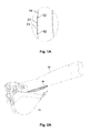
- arm 16 further includes a first gripping device 21 having a first gripping feature 23. Additionally, near first gripping device 21, a pair of slots 52 may be formed in arm 16 for securing a second gripping device 44 ( FIG. 2A ) , as will be discussed in further detail below.
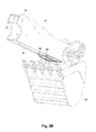
- a second gripping device 44 is removably secured to one or more of opposed side plates 17 of arm 16.
- a bottom plate 19 is positioned between opposed side plates 17 of arm 16, forming a box structure for providing additional rigidity and structural strength of the arm 16.
- second gripping device 44 includes a second gripping feature 46 for gripping objects between arm 16 and attachment 18 ( FIG. 2A ).
- second gripping device 44 is sized or configured to at least partially secure an object between the second gripping device 44 and attachment 18. That is, second gripping device 44 may be sized and/or positioned to supplement the first gripping device 21 ( FIGS. 4A, 4B ) with gripping an object between arm 16 and attachment 18. Alternately, second gripping device 44 may be sized and/or positioned such that only second gripping device 44, and not first gripping device 21, is utilized with gripping an object between arm 16 and attachment 18. As further shown in FIG.
- second gripping device 44 further includes a formed profile 48, such as a chamfer, such that a surface 56 of second gripping device 44 opposite second gripping feature 46 and a surface 58 adjacent second gripping feature 46 may be brought into conformal contact with a pair of corresponding surfaces 60, 62 of respective side plate 17 and bottom plate 19 of arm 16, when second gripping device 44 is secured to arm 16.
- formed profile 48 of second gripping device 44 provides clearance of a weld joint or weld 15 securing side plate 17 and bottom plate 19 of arm 16 together. By virtue of this conformal contact, bottom plate 19 and side plate 17 of arm 16 provide structural support and rigidity to second gripping device 44.
- slots 52 formed in the second gripping device 44 corresponds to openings (not shown) formed in side plate 17 of arm 16 (see FIG. 4B ).
- This arrangement in combination with formed profile 48 as discussed above, permit second gripping device 44 to be interchangeably assembled to side plate 17 of arm 16. While not shown in the figures, it may be desirable to secure second gripping device 44 to side plate(s) 17 along a surface opposite surface 60 (see FIG. 3C ).
- second gripping device 44 may include a centerline 72 defining an axis of symmetry for the second gripping device. However, in another embodiment, second gripping device 44 is not symmetric about centerline 72.
- first gripping feature 23 of first gripping device 21 may be similar to a corresponding second gripping feature 46 of second gripping device 44.
- first gripping feature 23 of first gripping device 21 may be different from a corresponding second gripping feature 46 of second gripping device 44.
- first gripping device 21 and second gripping device 44 may be formed using different heat treatment techniques.
- second gripping device 44 is formed using a heat treatment technique such that second gripping features 46 are "harder" than corresponding first gripping features 23 of first gripping device 21.
- Considerable cost savings may be realized by utilizing such a heat treatment technique for second gripping device 44, due to second gripping device 44 being much smaller than side plate 17 of arm 16 in which first gripping device 21 is integrally formed.
- second gripping device 44 in an environment with objects that have a high degree of abrasiveness would result in second gripping devices 44 being subjected to the abrasive environment, and not the corresponding first gripping device 21 of arm 16, thereby extending the service life of arm 16.
- second gripping device 44 includes a resilient layer 50, such as rubber or other suitable material, permitting gripping surfaces 47 associated with second gripping features 46 of second gripping device 44 to more gently manipulate objects 68 ( FIG. 4C ) such as a pipe.
- layer 50 is removably securable to second gripping device 44 using both fasteners 54 and corresponding slots 52 associated with arm 16 and second gripping device 44, as well as slots 64 and corresponding fasteners 66 associated with second gripping device 44 and layer 50.
- layer 50 is molded such that at least a portion of layer 50 extends over at least a portion of second gripping feature 46. As further shown FIG. 4F , layer 50 includes strips that may be directly secured over gripping surface 47 of second gripping device 44. Fasteners 70 may include countersunk fasteners such that the fastener heads are recessed so that the surface of the strips associated with gripping surface 47 do not mar or otherwise contact a surface of an object that is to be manipulated by the working machine.
- FIGS. 5A, 5B show different gripping surfaces 47 associated with different embodiments of second gripping devices 44, permitting, for example, effective use of gripping surfaces 47 with differently sized pipes or other objects.
- a resilient layer 50 such as previously discussed (see FIG. 4F ) may be utilized.
- second gripping device 44 may include a second gripping feature 46 for different applications, such as a jagged teeth arrangement for use with brush or undergrowth or other suitable application.
Landscapes
- Engineering & Computer Science (AREA)
- Mechanical Engineering (AREA)
- Mining & Mineral Resources (AREA)
- Civil Engineering (AREA)
- General Engineering & Computer Science (AREA)
- Structural Engineering (AREA)
- Manipulator (AREA)
- Feeding Of Workpieces (AREA)
Applications Claiming Priority (1)
| Application Number | Priority Date | Filing Date | Title |
|---|---|---|---|
| US13/343,781 US8926257B2 (en) | 2012-01-05 | 2012-01-05 | Gripping device for articulated work machine |
Publications (2)
| Publication Number | Publication Date |
|---|---|
| EP2612971A2 true EP2612971A2 (de) | 2013-07-10 |
| EP2612971A3 EP2612971A3 (de) | 2017-08-16 |
Family
ID=47603064
Family Applications (1)
| Application Number | Title | Priority Date | Filing Date |
|---|---|---|---|
| EP12198458.7A Withdrawn EP2612971A3 (de) | 2012-01-05 | 2012-12-20 | Greifvorrichtung für bewegliche Arbeitsmaschine |
Country Status (3)
| Country | Link |
|---|---|
| US (1) | US8926257B2 (de) |
| EP (1) | EP2612971A3 (de) |
| BR (1) | BR102013000423A8 (de) |
Cited By (1)
| Publication number | Priority date | Publication date | Assignee | Title |
|---|---|---|---|---|
| CN106065637A (zh) * | 2015-04-21 | 2016-11-02 | J.C.班福德挖掘机有限公司 | 附接件的安装方法 |
Family Cites Families (14)
| Publication number | Priority date | Publication date | Assignee | Title |
|---|---|---|---|---|
| US3120310A (en) | 1960-05-20 | 1964-02-04 | Kenneth E Roberts | Tilting-boom log-handling crane |
| GB1070877A (en) * | 1964-09-19 | 1967-06-07 | Gkn Group Services Ltd | Bucket assembly for a bucket loader |
| US3353285A (en) | 1965-06-24 | 1967-11-21 | Donald W Murray | Backhoe attachment |
| US4407626A (en) | 1981-01-30 | 1983-10-04 | Bruckner Peter J | Gripping device |
| US4517755A (en) * | 1983-07-18 | 1985-05-21 | Walter Nicholson | Multi-tined claw/rake attachment |
| GB2186258B (en) | 1986-11-19 | 1990-03-28 | Philip Anthony Smith | An excavator provided with means to enable elongate objects to be handled |
| US4770597A (en) | 1987-06-26 | 1988-09-13 | Powers Richard S | Clamping device for a backhoe |
| US5678332A (en) * | 1996-06-24 | 1997-10-21 | Hawkins; Bobby Leonard | Changeable and retractable implement for use on a back hoe and method |
| US6203267B1 (en) | 1999-08-03 | 2001-03-20 | Rockland Inc. | Material handling assembly for machines and thumb assembly thereof |
| US6209237B1 (en) | 1999-08-04 | 2001-04-03 | Rockland Inc. | Material handling assembly for excavating machines and the like having improved component storage means |
| US7037064B2 (en) | 2004-02-26 | 2006-05-02 | Rockland, Inc. | Grapple assembly for excavating machines and the like |
| US20060283056A1 (en) * | 2005-06-17 | 2006-12-21 | Amulet Manufacturing Company | Gripping attachment for backhoe or excavator |
| US8567836B2 (en) * | 2007-08-31 | 2013-10-29 | Lavalley Industries, Llc | Gripping assembly and gripping members for a grapple attachment |
| US20090290966A1 (en) * | 2008-05-20 | 2009-11-26 | George King | Thumb Accessory for Extendable Dipper Stick |
-
2012
- 2012-01-05 US US13/343,781 patent/US8926257B2/en active Active
- 2012-12-20 EP EP12198458.7A patent/EP2612971A3/de not_active Withdrawn
-
2013
- 2013-01-07 BR BR102013000423A patent/BR102013000423A8/pt not_active Application Discontinuation
Non-Patent Citations (1)
| Title |
|---|
| None |
Cited By (3)
| Publication number | Priority date | Publication date | Assignee | Title |
|---|---|---|---|---|
| CN106065637A (zh) * | 2015-04-21 | 2016-11-02 | J.C.班福德挖掘机有限公司 | 附接件的安装方法 |
| EP3088611A1 (de) * | 2015-04-21 | 2016-11-02 | J.C. Bamford Excavators Limited | Verfahren zur montage eines aufsatzes |
| US10753064B2 (en) | 2015-04-21 | 2020-08-25 | J.C. Bamford Excavators Limited | Arm for material handling machine |
Also Published As
| Publication number | Publication date |
|---|---|
| EP2612971A3 (de) | 2017-08-16 |
| US20130177382A1 (en) | 2013-07-11 |
| US8926257B2 (en) | 2015-01-06 |
| BR102013000423A2 (pt) | 2013-11-05 |
| BR102013000423A8 (pt) | 2017-03-28 |
Similar Documents
| Publication | Publication Date | Title |
|---|---|---|
| US10047504B2 (en) | Shroud retention system having replaceable lug insert | |
| AU2016274242B2 (en) | Spacer shims for ground engaging tools | |
| CN104093916B (zh) | 垫磨片组件 | |
| CN113795631A (zh) | 用于将尖端附接到机器机具的适配器和地面接合工具组件 | |
| US20140059900A1 (en) | Excavating bucket for construction machine | |
| JP2016008622A (ja) | 建設機械の配管支持具 | |
| CN106687646A (zh) | 机具切割边缘磨损构件 | |
| JP6899808B2 (ja) | 建設機械 | |
| US10794041B2 (en) | Stabilizer pad for a work machine | |
| CN106715804A (zh) | 机具端部刀头磨损构件 | |
| US8926257B2 (en) | Gripping device for articulated work machine | |
| US11142884B1 (en) | Excavator scraper attachment | |
| JP4597934B2 (ja) | 掘削装置のカッティングエッジの摩耗防止板 | |
| AU2019467236B2 (en) | Replaceable basket for a bucket for a machine | |
| CN209686477U (zh) | 推土铲装置和推土机 | |
| US20250034832A1 (en) | Bucket with multiple radius wrapper | |
| JP3200975U (ja) | 掴み爪 | |
| US10378174B2 (en) | Interface for coupling work tool to machine | |
| JP3066955U (ja) | 掘削機械用バッケトの整地作業用アタッチメントの鋼板 | |
| CN117813431A (zh) | 具有结构支撑的挖掘机拇指 | |
| CA3211586A1 (en) | Linkage for arm assembly with reduced weld fatigue | |
| BR112022005389B1 (pt) | Cesta para montagem substituível em um corpo principal para formar uma caçamba para uma máquina, caçamba para uma máquina e máquina |
Legal Events
| Date | Code | Title | Description |
|---|---|---|---|
| PUAI | Public reference made under article 153(3) epc to a published international application that has entered the european phase |
Free format text: ORIGINAL CODE: 0009012 |
|
| AK | Designated contracting states |
Kind code of ref document: A2 Designated state(s): AL AT BE BG CH CY CZ DE DK EE ES FI FR GB GR HR HU IE IS IT LI LT LU LV MC MK MT NL NO PL PT RO RS SE SI SK SM TR |
|
| AX | Request for extension of the european patent |
Extension state: BA ME |
|
| RAP1 | Party data changed (applicant data changed or rights of an application transferred) |
Owner name: CNH INDUSTRIAL BELGIUM NV |
|
| PUAL | Search report despatched |
Free format text: ORIGINAL CODE: 0009013 |
|
| AK | Designated contracting states |
Kind code of ref document: A3 Designated state(s): AL AT BE BG CH CY CZ DE DK EE ES FI FR GB GR HR HU IE IS IT LI LT LU LV MC MK MT NL NO PL PT RO RS SE SI SK SM TR |
|
| AX | Request for extension of the european patent |
Extension state: BA ME |
|
| RIC1 | Information provided on ipc code assigned before grant |
Ipc: E02F 3/40 20060101AFI20170710BHEP Ipc: E02F 3/36 20060101ALI20170710BHEP |
|
| 17P | Request for examination filed |
Effective date: 20180216 |
|
| RBV | Designated contracting states (corrected) |
Designated state(s): AL AT BE BG CH CY CZ DE DK EE ES FI FR GB GR HR HU IE IS IT LI LT LU LV MC MK MT NL NO PL PT RO RS SE SI SK SM TR |
|
| R17P | Request for examination filed (corrected) |
Effective date: 20180216 |
|
| STAA | Information on the status of an ep patent application or granted ep patent |
Free format text: STATUS: THE APPLICATION IS DEEMED TO BE WITHDRAWN |
|
| 18D | Application deemed to be withdrawn |
Effective date: 20180217 |