EP2612992A2 - Turbine et procédé de séparation des particules d'un fluide - Google Patents
Turbine et procédé de séparation des particules d'un fluide Download PDFInfo
- Publication number
- EP2612992A2 EP2612992A2 EP12197944.7A EP12197944A EP2612992A2 EP 2612992 A2 EP2612992 A2 EP 2612992A2 EP 12197944 A EP12197944 A EP 12197944A EP 2612992 A2 EP2612992 A2 EP 2612992A2
- Authority
- EP
- European Patent Office
- Prior art keywords
- fluid
- passage
- turbine
- particulates
- component
- Prior art date
- Legal status (The legal status is an assumption and is not a legal conclusion. Google has not performed a legal analysis and makes no representation as to the accuracy of the status listed.)
- Granted
Links
- 239000012530 fluid Substances 0.000 title claims abstract description 83
- 238000000034 method Methods 0.000 title claims description 13
- 238000001816 cooling Methods 0.000 claims description 10
- 239000000428 dust Substances 0.000 claims description 7
- 238000000576 coating method Methods 0.000 claims description 3
- 239000002184 metal Substances 0.000 claims description 3
- 239000003973 paint Substances 0.000 claims description 3
- 238000000926 separation method Methods 0.000 claims description 2
- 239000007789 gas Substances 0.000 description 14
- 239000000446 fuel Substances 0.000 description 11
- 239000012809 cooling fluid Substances 0.000 description 6
- 239000011148 porous material Substances 0.000 description 4
- 239000006262 metallic foam Substances 0.000 description 3
- 239000000203 mixture Substances 0.000 description 3
- 230000015556 catabolic process Effects 0.000 description 2
- 238000006731 degradation reaction Methods 0.000 description 2
- 239000000463 material Substances 0.000 description 2
- VNWKTOKETHGBQD-UHFFFAOYSA-N methane Chemical compound C VNWKTOKETHGBQD-UHFFFAOYSA-N 0.000 description 2
- 238000011144 upstream manufacturing Methods 0.000 description 2
- UFHFLCQGNIYNRP-UHFFFAOYSA-N Hydrogen Chemical compound [H][H] UFHFLCQGNIYNRP-UHFFFAOYSA-N 0.000 description 1
- 230000001154 acute effect Effects 0.000 description 1
- 230000004075 alteration Effects 0.000 description 1
- 238000006243 chemical reaction Methods 0.000 description 1
- 238000002485 combustion reaction Methods 0.000 description 1
- 238000010586 diagram Methods 0.000 description 1
- 238000010304 firing Methods 0.000 description 1
- 239000006260 foam Substances 0.000 description 1
- 239000001257 hydrogen Substances 0.000 description 1
- 229910052739 hydrogen Inorganic materials 0.000 description 1
- 239000007788 liquid Substances 0.000 description 1
- 239000003345 natural gas Substances 0.000 description 1
- 239000000126 substance Substances 0.000 description 1
- 238000006467 substitution reaction Methods 0.000 description 1
- 230000008646 thermal stress Effects 0.000 description 1
- 230000007704 transition Effects 0.000 description 1
Images
Classifications
-
- F—MECHANICAL ENGINEERING; LIGHTING; HEATING; WEAPONS; BLASTING
- F01—MACHINES OR ENGINES IN GENERAL; ENGINE PLANTS IN GENERAL; STEAM ENGINES
- F01D—NON-POSITIVE DISPLACEMENT MACHINES OR ENGINES, e.g. STEAM TURBINES
- F01D5/00—Blades; Blade-carrying members; Heating, heat-insulating, cooling or antivibration means on the blades or the members
- F01D5/12—Blades
- F01D5/14—Form or construction
- F01D5/18—Hollow blades, i.e. blades with cooling or heating channels or cavities; Heating, heat-insulating or cooling means on blades
- F01D5/187—Convection cooling
-
- F—MECHANICAL ENGINEERING; LIGHTING; HEATING; WEAPONS; BLASTING
- F05—INDEXING SCHEMES RELATING TO ENGINES OR PUMPS IN VARIOUS SUBCLASSES OF CLASSES F01-F04
- F05D—INDEXING SCHEME FOR ASPECTS RELATING TO NON-POSITIVE-DISPLACEMENT MACHINES OR ENGINES, GAS-TURBINES OR JET-PROPULSION PLANTS
- F05D2250/00—Geometry
- F05D2250/70—Shape
- F05D2250/71—Shape curved
-
- F—MECHANICAL ENGINEERING; LIGHTING; HEATING; WEAPONS; BLASTING
- F05—INDEXING SCHEMES RELATING TO ENGINES OR PUMPS IN VARIOUS SUBCLASSES OF CLASSES F01-F04
- F05D—INDEXING SCHEME FOR ASPECTS RELATING TO NON-POSITIVE-DISPLACEMENT MACHINES OR ENGINES, GAS-TURBINES OR JET-PROPULSION PLANTS
- F05D2260/00—Function
- F05D2260/60—Fluid transfer
- F05D2260/607—Preventing clogging or obstruction of flow paths by dirt, dust, or foreign particles
-
- F—MECHANICAL ENGINEERING; LIGHTING; HEATING; WEAPONS; BLASTING
- F05—INDEXING SCHEMES RELATING TO ENGINES OR PUMPS IN VARIOUS SUBCLASSES OF CLASSES F01-F04
- F05D—INDEXING SCHEME FOR ASPECTS RELATING TO NON-POSITIVE-DISPLACEMENT MACHINES OR ENGINES, GAS-TURBINES OR JET-PROPULSION PLANTS
- F05D2300/00—Materials; Properties thereof
- F05D2300/60—Properties or characteristics given to material by treatment or manufacturing
- F05D2300/612—Foam
Definitions
- the subject matter disclosed herein relates to turbine engines and, more particularly, to an apparatus and method for separating particulates from a fluid in turbine engines.
- a combustor converts the chemical energy of a fuel or an air-fuel mixture into thermal energy.
- the thermal energy is conveyed by a fluid, often compressed air from a compressor, to a turbine where the thermal energy is converted to mechanical energy.
- a fluid often compressed air from a compressor
- turbine As part of the conversion process, hot gas is flowed over and through portions of the turbine. High temperatures along the hot gas path can heat turbine components, causing degradation.
- a cooling fluid may flow through channels or cavities formed within the components to cool the components.
- the cooling fluid may include particulates, such as dust or dirt, which can build up in flow passages and disrupt flow. Reduced flow or restriction of the cooling fluid can lead to increased temperatures and thermal stress on turbine components.
- a turbine component includes a first cavity inside the turbine component configured to receive a fluid and a second cavity inside the turbine component.
- the turbine component also includes a passage inside the turbine component that provides fluid communication between the first and second cavities, wherein the passage includes a curved portion configured to separate particulates from the fluid as the fluid flows through the passage.
- a method for separating particulates from a fluid flowing within a turbine component includes receiving a fluid from a first cavity within the turbine component into a passage within the turbine component, wherein the passage includes a curved portion configured to separate particulates from the fluid as the fluid flows through the passage. The method also includes directing a clean fluid with a reduced amount of particulates from the passage to a second cavity within the turbine component.
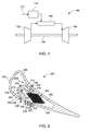
- FIG. 1 is a schematic diagram of an embodiment of a gas turbine system 100.
- the system 100 includes a compressor 102, a combustor 104, a turbine 106, a shaft 108 and a fuel nozzle 110.
- the system 100 may include a plurality of compressors 102, combustors 104, turbines 106, shafts 108 and fuel nozzles 110.
- the compressor 102 and turbine 106 are coupled by the shaft 108.
- the shaft 108 may be a single shaft or a plurality of shaft segments coupled together to form shaft 108.
- the combustor 104 uses liquid and/or gas fuel, such as natural gas or a hydrogen rich synthetic gas, to run the engine.
- fuel nozzles 110 are in fluid communication with an air supply and a fuel supply 112.
- the fuel nozzles 110 create an air-fuel mixture, and discharge the air-fuel mixture into the combustor 104, thereby causing a combustion that heats a pressurized gas.
- the combustor 104 directs the hot pressurized exhaust gas through a transition piece into a turbine nozzle (or "stage one nozzle") and then a turbine bucket, causing turbine 106 rotation.
- the rotation of turbine 106 causes the shaft 108 to rotate, thereby compressing the air as it flows into the compressor 102.
- the hot gas path components should be properly cooled to extend service life.
- hot gas flows over and through portions of of the gas turbine system 100, including the turbine 106.
- High temperatures along the hot gas path can heat components of the turbine 106, causing degradation.
- a cooling fluid may flow through channels or cavities formed within the components to cool the components.
- the cooling fluid may include particulates, such as dust, ground metal dust, paint chips and chipped coatings, which can build up in flow passages and disrupt flow. Components with improved arrangements for removing particulates from a flow of cooling fluid and methods for using such components are discussed in detail below with reference to FIG. 2 .
- downstream and upstream are terms that indicate a direction relative to the flow of working fluid through the turbine.
- downstream refers to a direction that generally corresponds to the direction of the flow of working fluid
- upstream generally refers to the direction that is opposite of the direction of flow of working fluid.
- radial refers to movement or position perpendicular to an axis or center line. It may be useful to describe parts that are at differing radial positions with regard to an axis. In this case, if a first component resides closer to the axis than a second component, it may be stated herein that the first component is "radially inward" of the second component.
- first component resides further from the axis than the second component, it may be stated herein that the first component is “radially outward” or “outboard” of the second component.
- axial refers to movement or position parallel to an axis.
- circumferential refers to movement or position around an axis.
- FIG. 2 is a sectional top view of an embodiment of a turbine component, such as an airfoil 200.
- the airfoil 200 includes an outer wall 202 containing a leading edge (LE) cavity 204 and a trailing edge (TE) cavity 206, wherein the cavities are configured to receive a fluid to control the temperature of portions of the airfoil 200.
- the LE cavity 204 receives a fluid 208, such as air, used to cool portions of the airfoil 200.
- a passage 210 receives the fluid 208 and separates particulates from the fluid 208 as it flows through the passage 210.
- the passage 210 includes a substantially straight portion 212 and a substantially curved portion 214, wherein a hairpin portion 216 connects the substantially straight portion 212 to the substantially curved portion 214.
- a centrifugal force acts on the flowing fluid 208 to cause or urge particulates to flow toward a radially outer wall 218 of the curved portion 214, due to the higher mass of the particulates relative to the fluid. Accordingly, the fluid 208 proximate a radially inner wall 220 has a reduced amount of particulates.
- a clean fluid 222 comprising the fluid 208 with a reduced amount of particulates proximate the radially inner wall 220 flows through a passage 224 in the radially inner wall 220.
- the remaining fluid 208 includes an increased amount of particulates and forms a fluid 226 (also referred to as "remaining fluid") that flows through a passage 228 in the outer wall 202 proximate an end or downstream portion of the passage 210.
- the fluid 226 flows through the passage 228 and forms a film that cools a surface 230 of the outer wall 202.
- the TE cavity 206 receives the clean fluid 222 with a reduced amount of particulates, wherein the clean fluid 222 is directed to other locations, such as passages, channels and/or other cavities for controlling temperature within the airfoil 200.
- passages 232 in the outer wall 202 enable clean fluid 234 to flow from the TE cavity 206, wherein the clean fluid 234 cools the outer wall proximate the passages 232.
- the reduced amount of particulates in the clean fluid 234 enables fluid flow through channels or passages, such as passages 232, without particulate buildup that can restrict fluid flow.
- the passages 232 are small diameter cooling passages.
- Small diameter cooling passages (e.g., passages 232) provide enhanced control of cooling for selected portions of turbine parts and, thus, are susceptible to blockage. Accordingly, by reducing buildup of particulates in the fluid flowing through the flow channels and passages, enhanced control of turbine part temperatures is provided to prevent thermal fatigue, wear and/or damage.
- a porous material such as metal foam 236, may receive the clean fluid 222, wherein pores in the foam are fluid flow passages for cooling portions of the airfoil 200.
- the connected pore passages of the metal foam 236 allow clean fluid 222, such as cooling air, to fill at least part of the TE cavity 206 and thus increase the surface area for the cooling air to flow over.
- the reduced particulates in clean fluid 222 reduce blockage of pore passages in the metal foam 236, therefore improve cooling.
- the passage 210 includes a passage 240 in outer wall 202 proximate the hairpin portion 216, wherein a flow of fluid 238 includes an increased amount of particulates.
- the depicted arrangement of the passage 210 in the airfoil 200 may be used to separate higher mass material, such as particulates, from a fluid inside any suitable turbine components including, but not limited to, airfoils, shrouds and bulkheads.
- the passage 210 with the substantially curved portion 214 may be located in any suitable location within the turbine component, wherein the passage receives the fluid with particulates and separates the particulates by centrifugal force and the clean fluid 222 flows to another location for further component cooling.
- a hairpin passage includes a flow path with a very acute inner angle turn, making a substantial amount of the fluid flow turn almost 180° to continue flow along the passage.
- a curved passage fluid to flow in a substantially curved path that also causes a centrifugal force to urge higher mass material to a radially outer wall of the passage.
- the curve passage geometry include an arc, half circle and a plurality of straight portions with small angles between them (forming a substantially arc-shaped curve flow path).
- the depicted passage 210 in the component may be in fluid communication with cavities, channels or passages located within or outside the turbine component, wherein the passage 210 is configured to reduce the amount of particulates within the fluid 208 and provide the clean fluid 222 to the second cavity (i.e., TE cavity 206).
Landscapes
- Engineering & Computer Science (AREA)
- Mechanical Engineering (AREA)
- General Engineering & Computer Science (AREA)
- Turbine Rotor Nozzle Sealing (AREA)
- Separating Particles In Gases By Inertia (AREA)
Applications Claiming Priority (1)
| Application Number | Priority Date | Filing Date | Title |
|---|---|---|---|
| US13/342,556 US8961111B2 (en) | 2012-01-03 | 2012-01-03 | Turbine and method for separating particulates from a fluid |
Publications (3)
| Publication Number | Publication Date |
|---|---|
| EP2612992A2 true EP2612992A2 (fr) | 2013-07-10 |
| EP2612992A3 EP2612992A3 (fr) | 2018-03-14 |
| EP2612992B1 EP2612992B1 (fr) | 2019-11-06 |
Family
ID=47603013
Family Applications (1)
| Application Number | Title | Priority Date | Filing Date |
|---|---|---|---|
| EP12197944.7A Active EP2612992B1 (fr) | 2012-01-03 | 2012-12-19 | Turbine et procédé de séparation des particules d'un fluide |
Country Status (5)
| Country | Link |
|---|---|
| US (1) | US8961111B2 (fr) |
| EP (1) | EP2612992B1 (fr) |
| JP (1) | JP6405077B2 (fr) |
| CN (1) | CN103184888B (fr) |
| RU (1) | RU2012158329A (fr) |
Families Citing this family (7)
| Publication number | Priority date | Publication date | Assignee | Title |
|---|---|---|---|---|
| US8535006B2 (en) * | 2010-07-14 | 2013-09-17 | Siemens Energy, Inc. | Near-wall serpentine cooled turbine airfoil |
| CN104204412B (zh) * | 2012-03-22 | 2016-09-28 | 通用电器技术有限公司 | 涡轮叶片 |
| US9650905B2 (en) * | 2012-08-28 | 2017-05-16 | United Technologies Corporation | Singlet vane cluster assembly |
| US10227930B2 (en) | 2016-03-28 | 2019-03-12 | General Electric Company | Compressor bleed systems in turbomachines and methods of extracting compressor airflow |
| US10669896B2 (en) | 2018-01-17 | 2020-06-02 | Raytheon Technologies Corporation | Dirt separator for internally cooled components |
| GB2572170A (en) * | 2018-03-21 | 2019-09-25 | Rolls Royce Plc | Removing entrained particles |
| US11391161B2 (en) * | 2018-07-19 | 2022-07-19 | General Electric Company | Component for a turbine engine with a cooling hole |
Family Cites Families (14)
| Publication number | Priority date | Publication date | Assignee | Title |
|---|---|---|---|---|
| US3362155A (en) | 1965-03-29 | 1968-01-09 | Gen Electric | Axial flow separator |
| US3309567A (en) | 1965-10-22 | 1967-03-14 | Berkey Photo Inc | Pulse discharge lamp circuit |
| US3338049A (en) | 1966-02-01 | 1967-08-29 | Gen Electric | Gas turbine engine including separator for removing extraneous matter |
| US4685942A (en) | 1982-12-27 | 1987-08-11 | General Electric Company | Axial flow inlet particle separator |
| DE68906594T2 (de) * | 1988-04-25 | 1993-08-26 | United Technologies Corp | Staubabscheider fuer eine luftgekuehlte schaufel. |
| US5700131A (en) * | 1988-08-24 | 1997-12-23 | United Technologies Corporation | Cooled blades for a gas turbine engine |
| GB2228540B (en) * | 1988-12-07 | 1993-03-31 | Rolls Royce Plc | Cooling of turbine blades |
| SE527932C2 (sv) * | 2004-02-27 | 2006-07-11 | Demag Delaval Ind Turbomachine | Ett rotorblad eller en ledskena för en rotormaskin, såsom en gasturbin |
| GB0524735D0 (en) * | 2005-12-03 | 2006-01-11 | Rolls Royce Plc | Turbine blade |
| US7695243B2 (en) * | 2006-07-27 | 2010-04-13 | General Electric Company | Dust hole dome blade |
| US7665965B1 (en) * | 2007-01-17 | 2010-02-23 | Florida Turbine Technologies, Inc. | Turbine rotor disk with dirt particle separator |
| GB2452327B (en) * | 2007-09-01 | 2010-02-03 | Rolls Royce Plc | A cooled component |
| FR2943092B1 (fr) * | 2009-03-13 | 2011-04-15 | Snecma | Aube de turbine avec un trou de depoussierage en base de pale |
| US8176720B2 (en) * | 2009-09-22 | 2012-05-15 | Siemens Energy, Inc. | Air cooled turbine component having an internal filtration system |
-
2012
- 2012-01-03 US US13/342,556 patent/US8961111B2/en active Active
- 2012-12-19 EP EP12197944.7A patent/EP2612992B1/fr active Active
- 2012-12-27 RU RU2012158329/06A patent/RU2012158329A/ru not_active Application Discontinuation
- 2012-12-27 JP JP2012283887A patent/JP6405077B2/ja active Active
-
2013
- 2013-01-04 CN CN201310001629.3A patent/CN103184888B/zh active Active
Non-Patent Citations (1)
| Title |
|---|
| None |
Also Published As
| Publication number | Publication date |
|---|---|
| JP6405077B2 (ja) | 2018-10-17 |
| EP2612992B1 (fr) | 2019-11-06 |
| RU2012158329A (ru) | 2014-07-10 |
| EP2612992A3 (fr) | 2018-03-14 |
| CN103184888B (zh) | 2016-04-13 |
| CN103184888A (zh) | 2013-07-03 |
| JP2013139811A (ja) | 2013-07-18 |
| US20130170982A1 (en) | 2013-07-04 |
| US8961111B2 (en) | 2015-02-24 |
Similar Documents
| Publication | Publication Date | Title |
|---|---|---|
| EP3244011B1 (fr) | Système de refroidissement de rails d'étanchéité de carénage d'extrémité d'aube de turbine | |
| US8961111B2 (en) | Turbine and method for separating particulates from a fluid | |
| US10196982B2 (en) | Gas turbine engine having a flow control surface with a cooling conduit | |
| US11156099B2 (en) | Turbine engine airfoil with a modified leading edge | |
| US20100166558A1 (en) | Methods and apparatus relating to improved turbine blade platform contours | |
| CN109931113B (zh) | 具有冷却孔的发动机部件 | |
| US10927682B2 (en) | Engine component with non-diffusing section | |
| US20220213802A1 (en) | System for controlling blade clearances within a gas turbine engine | |
| CA2946591A1 (fr) | Moteur de turbine a gaz dote d'une aube comportant une buse pivotante d'air de refroidissement | |
| US20120195742A1 (en) | Turbine bucket for use in gas turbine engines and methods for fabricating the same | |
| CN107201920A (zh) | 具有膜孔的用于涡轮发动机的部件 | |
| EP2669476A2 (fr) | Ensemble de refroidissement pour une aube d'un système de turbine et procédé de refroidissement associé | |
| JP7297413B2 (ja) | ターボ機械用ロータブレード | |
| US20170226868A1 (en) | Gas turbine engine airfoil | |
| US10808547B2 (en) | Turbine engine airfoil with cooling | |
| CN208106502U (zh) | 叶片及涡轮机 | |
| EP2613006A1 (fr) | Ensemble de turbine et procédé permettant de réduire l'écoulement de fluide entre des composants de turbine | |
| US7534085B2 (en) | Gas turbine engine with contoured air supply slot in turbine rotor | |
| EP3495623B1 (fr) | Aube statorique, moteur à turbine à gaz et turbine associés | |
| EP3203026B1 (fr) | Pale de turbine à gaz avec réseau de socle | |
| US20140050558A1 (en) | Temperature gradient management arrangement for a turbine system and method of managing a temperature gradient of a turbine system |
Legal Events
| Date | Code | Title | Description |
|---|---|---|---|
| PUAI | Public reference made under article 153(3) epc to a published international application that has entered the european phase |
Free format text: ORIGINAL CODE: 0009012 |
|
| AK | Designated contracting states |
Kind code of ref document: A2 Designated state(s): AL AT BE BG CH CY CZ DE DK EE ES FI FR GB GR HR HU IE IS IT LI LT LU LV MC MK MT NL NO PL PT RO RS SE SI SK SM TR |
|
| AX | Request for extension of the european patent |
Extension state: BA ME |
|
| PUAL | Search report despatched |
Free format text: ORIGINAL CODE: 0009013 |
|
| AK | Designated contracting states |
Kind code of ref document: A3 Designated state(s): AL AT BE BG CH CY CZ DE DK EE ES FI FR GB GR HR HU IE IS IT LI LT LU LV MC MK MT NL NO PL PT RO RS SE SI SK SM TR |
|
| AX | Request for extension of the european patent |
Extension state: BA ME |
|
| RIC1 | Information provided on ipc code assigned before grant |
Ipc: F01D 5/18 20060101AFI20180205BHEP |
|
| STAA | Information on the status of an ep patent application or granted ep patent |
Free format text: STATUS: REQUEST FOR EXAMINATION WAS MADE |
|
| 17P | Request for examination filed |
Effective date: 20180914 |
|
| RBV | Designated contracting states (corrected) |
Designated state(s): AL AT BE BG CH CY CZ DE DK EE ES FI FR GB GR HR HU IE IS IT LI LT LU LV MC MK MT NL NO PL PT RO RS SE SI SK SM TR |
|
| GRAP | Despatch of communication of intention to grant a patent |
Free format text: ORIGINAL CODE: EPIDOSNIGR1 |
|
| STAA | Information on the status of an ep patent application or granted ep patent |
Free format text: STATUS: GRANT OF PATENT IS INTENDED |
|
| INTG | Intention to grant announced |
Effective date: 20190517 |
|
| GRAS | Grant fee paid |
Free format text: ORIGINAL CODE: EPIDOSNIGR3 |
|
| GRAA | (expected) grant |
Free format text: ORIGINAL CODE: 0009210 |
|
| STAA | Information on the status of an ep patent application or granted ep patent |
Free format text: STATUS: THE PATENT HAS BEEN GRANTED |
|
| AK | Designated contracting states |
Kind code of ref document: B1 Designated state(s): AL AT BE BG CH CY CZ DE DK EE ES FI FR GB GR HR HU IE IS IT LI LT LU LV MC MK MT NL NO PL PT RO RS SE SI SK SM TR |
|
| REG | Reference to a national code |
Ref country code: GB Ref legal event code: FG4D |
|
| REG | Reference to a national code |
Ref country code: CH Ref legal event code: EP Ref country code: AT Ref legal event code: REF Ref document number: 1198969 Country of ref document: AT Kind code of ref document: T Effective date: 20191115 |
|
| REG | Reference to a national code |
Ref country code: IE Ref legal event code: FG4D |
|
| REG | Reference to a national code |
Ref country code: DE Ref legal event code: R096 Ref document number: 602012065403 Country of ref document: DE |
|
| REG | Reference to a national code |
Ref country code: NL Ref legal event code: MP Effective date: 20191106 |
|
| REG | Reference to a national code |
Ref country code: LT Ref legal event code: MG4D |
|
| PG25 | Lapsed in a contracting state [announced via postgrant information from national office to epo] |
Ref country code: PT Free format text: LAPSE BECAUSE OF FAILURE TO SUBMIT A TRANSLATION OF THE DESCRIPTION OR TO PAY THE FEE WITHIN THE PRESCRIBED TIME-LIMIT Effective date: 20200306 Ref country code: FI Free format text: LAPSE BECAUSE OF FAILURE TO SUBMIT A TRANSLATION OF THE DESCRIPTION OR TO PAY THE FEE WITHIN THE PRESCRIBED TIME-LIMIT Effective date: 20191106 Ref country code: BG Free format text: LAPSE BECAUSE OF FAILURE TO SUBMIT A TRANSLATION OF THE DESCRIPTION OR TO PAY THE FEE WITHIN THE PRESCRIBED TIME-LIMIT Effective date: 20200206 Ref country code: LT Free format text: LAPSE BECAUSE OF FAILURE TO SUBMIT A TRANSLATION OF THE DESCRIPTION OR TO PAY THE FEE WITHIN THE PRESCRIBED TIME-LIMIT Effective date: 20191106 Ref country code: NL Free format text: LAPSE BECAUSE OF FAILURE TO SUBMIT A TRANSLATION OF THE DESCRIPTION OR TO PAY THE FEE WITHIN THE PRESCRIBED TIME-LIMIT Effective date: 20191106 Ref country code: PL Free format text: LAPSE BECAUSE OF FAILURE TO SUBMIT A TRANSLATION OF THE DESCRIPTION OR TO PAY THE FEE WITHIN THE PRESCRIBED TIME-LIMIT Effective date: 20191106 Ref country code: LV Free format text: LAPSE BECAUSE OF FAILURE TO SUBMIT A TRANSLATION OF THE DESCRIPTION OR TO PAY THE FEE WITHIN THE PRESCRIBED TIME-LIMIT Effective date: 20191106 Ref country code: NO Free format text: LAPSE BECAUSE OF FAILURE TO SUBMIT A TRANSLATION OF THE DESCRIPTION OR TO PAY THE FEE WITHIN THE PRESCRIBED TIME-LIMIT Effective date: 20200206 Ref country code: SE Free format text: LAPSE BECAUSE OF FAILURE TO SUBMIT A TRANSLATION OF THE DESCRIPTION OR TO PAY THE FEE WITHIN THE PRESCRIBED TIME-LIMIT Effective date: 20191106 Ref country code: ES Free format text: LAPSE BECAUSE OF FAILURE TO SUBMIT A TRANSLATION OF THE DESCRIPTION OR TO PAY THE FEE WITHIN THE PRESCRIBED TIME-LIMIT Effective date: 20191106 Ref country code: GR Free format text: LAPSE BECAUSE OF FAILURE TO SUBMIT A TRANSLATION OF THE DESCRIPTION OR TO PAY THE FEE WITHIN THE PRESCRIBED TIME-LIMIT Effective date: 20200207 |
|
| PG25 | Lapsed in a contracting state [announced via postgrant information from national office to epo] |
Ref country code: IS Free format text: LAPSE BECAUSE OF FAILURE TO SUBMIT A TRANSLATION OF THE DESCRIPTION OR TO PAY THE FEE WITHIN THE PRESCRIBED TIME-LIMIT Effective date: 20200306 Ref country code: HR Free format text: LAPSE BECAUSE OF FAILURE TO SUBMIT A TRANSLATION OF THE DESCRIPTION OR TO PAY THE FEE WITHIN THE PRESCRIBED TIME-LIMIT Effective date: 20191106 Ref country code: RS Free format text: LAPSE BECAUSE OF FAILURE TO SUBMIT A TRANSLATION OF THE DESCRIPTION OR TO PAY THE FEE WITHIN THE PRESCRIBED TIME-LIMIT Effective date: 20191106 |
|
| PG25 | Lapsed in a contracting state [announced via postgrant information from national office to epo] |
Ref country code: AL Free format text: LAPSE BECAUSE OF FAILURE TO SUBMIT A TRANSLATION OF THE DESCRIPTION OR TO PAY THE FEE WITHIN THE PRESCRIBED TIME-LIMIT Effective date: 20191106 |
|
| PG25 | Lapsed in a contracting state [announced via postgrant information from national office to epo] |
Ref country code: EE Free format text: LAPSE BECAUSE OF FAILURE TO SUBMIT A TRANSLATION OF THE DESCRIPTION OR TO PAY THE FEE WITHIN THE PRESCRIBED TIME-LIMIT Effective date: 20191106 Ref country code: DK Free format text: LAPSE BECAUSE OF FAILURE TO SUBMIT A TRANSLATION OF THE DESCRIPTION OR TO PAY THE FEE WITHIN THE PRESCRIBED TIME-LIMIT Effective date: 20191106 Ref country code: RO Free format text: LAPSE BECAUSE OF FAILURE TO SUBMIT A TRANSLATION OF THE DESCRIPTION OR TO PAY THE FEE WITHIN THE PRESCRIBED TIME-LIMIT Effective date: 20191106 Ref country code: CZ Free format text: LAPSE BECAUSE OF FAILURE TO SUBMIT A TRANSLATION OF THE DESCRIPTION OR TO PAY THE FEE WITHIN THE PRESCRIBED TIME-LIMIT Effective date: 20191106 |
|
| REG | Reference to a national code |
Ref country code: CH Ref legal event code: PL |
|
| REG | Reference to a national code |
Ref country code: DE Ref legal event code: R097 Ref document number: 602012065403 Country of ref document: DE |
|
| REG | Reference to a national code |
Ref country code: AT Ref legal event code: MK05 Ref document number: 1198969 Country of ref document: AT Kind code of ref document: T Effective date: 20191106 |
|
| REG | Reference to a national code |
Ref country code: BE Ref legal event code: MM Effective date: 20191231 |
|
| PG25 | Lapsed in a contracting state [announced via postgrant information from national office to epo] |
Ref country code: SM Free format text: LAPSE BECAUSE OF FAILURE TO SUBMIT A TRANSLATION OF THE DESCRIPTION OR TO PAY THE FEE WITHIN THE PRESCRIBED TIME-LIMIT Effective date: 20191106 Ref country code: MC Free format text: LAPSE BECAUSE OF FAILURE TO SUBMIT A TRANSLATION OF THE DESCRIPTION OR TO PAY THE FEE WITHIN THE PRESCRIBED TIME-LIMIT Effective date: 20191106 Ref country code: SK Free format text: LAPSE BECAUSE OF FAILURE TO SUBMIT A TRANSLATION OF THE DESCRIPTION OR TO PAY THE FEE WITHIN THE PRESCRIBED TIME-LIMIT Effective date: 20191106 |
|
| PLBE | No opposition filed within time limit |
Free format text: ORIGINAL CODE: 0009261 |
|
| STAA | Information on the status of an ep patent application or granted ep patent |
Free format text: STATUS: NO OPPOSITION FILED WITHIN TIME LIMIT |
|
| 26N | No opposition filed |
Effective date: 20200807 |
|
| GBPC | Gb: european patent ceased through non-payment of renewal fee |
Effective date: 20200206 |
|
| PG25 | Lapsed in a contracting state [announced via postgrant information from national office to epo] |
Ref country code: FR Free format text: LAPSE BECAUSE OF NON-PAYMENT OF DUE FEES Effective date: 20200106 Ref country code: LU Free format text: LAPSE BECAUSE OF NON-PAYMENT OF DUE FEES Effective date: 20191219 Ref country code: IE Free format text: LAPSE BECAUSE OF NON-PAYMENT OF DUE FEES Effective date: 20191219 |
|
| PG25 | Lapsed in a contracting state [announced via postgrant information from national office to epo] |
Ref country code: BE Free format text: LAPSE BECAUSE OF NON-PAYMENT OF DUE FEES Effective date: 20191231 Ref country code: SI Free format text: LAPSE BECAUSE OF FAILURE TO SUBMIT A TRANSLATION OF THE DESCRIPTION OR TO PAY THE FEE WITHIN THE PRESCRIBED TIME-LIMIT Effective date: 20191106 Ref country code: AT Free format text: LAPSE BECAUSE OF FAILURE TO SUBMIT A TRANSLATION OF THE DESCRIPTION OR TO PAY THE FEE WITHIN THE PRESCRIBED TIME-LIMIT Effective date: 20191106 Ref country code: LI Free format text: LAPSE BECAUSE OF NON-PAYMENT OF DUE FEES Effective date: 20191231 Ref country code: CH Free format text: LAPSE BECAUSE OF NON-PAYMENT OF DUE FEES Effective date: 20191231 |
|
| PG25 | Lapsed in a contracting state [announced via postgrant information from national office to epo] |
Ref country code: GB Free format text: LAPSE BECAUSE OF NON-PAYMENT OF DUE FEES Effective date: 20200206 Ref country code: IT Free format text: LAPSE BECAUSE OF FAILURE TO SUBMIT A TRANSLATION OF THE DESCRIPTION OR TO PAY THE FEE WITHIN THE PRESCRIBED TIME-LIMIT Effective date: 20191106 |
|
| PG25 | Lapsed in a contracting state [announced via postgrant information from national office to epo] |
Ref country code: CY Free format text: LAPSE BECAUSE OF FAILURE TO SUBMIT A TRANSLATION OF THE DESCRIPTION OR TO PAY THE FEE WITHIN THE PRESCRIBED TIME-LIMIT Effective date: 20191106 |
|
| PG25 | Lapsed in a contracting state [announced via postgrant information from national office to epo] |
Ref country code: HU Free format text: LAPSE BECAUSE OF FAILURE TO SUBMIT A TRANSLATION OF THE DESCRIPTION OR TO PAY THE FEE WITHIN THE PRESCRIBED TIME-LIMIT; INVALID AB INITIO Effective date: 20121219 Ref country code: MT Free format text: LAPSE BECAUSE OF FAILURE TO SUBMIT A TRANSLATION OF THE DESCRIPTION OR TO PAY THE FEE WITHIN THE PRESCRIBED TIME-LIMIT Effective date: 20191106 |
|
| PG25 | Lapsed in a contracting state [announced via postgrant information from national office to epo] |
Ref country code: TR Free format text: LAPSE BECAUSE OF FAILURE TO SUBMIT A TRANSLATION OF THE DESCRIPTION OR TO PAY THE FEE WITHIN THE PRESCRIBED TIME-LIMIT Effective date: 20191106 |
|
| PG25 | Lapsed in a contracting state [announced via postgrant information from national office to epo] |
Ref country code: MK Free format text: LAPSE BECAUSE OF FAILURE TO SUBMIT A TRANSLATION OF THE DESCRIPTION OR TO PAY THE FEE WITHIN THE PRESCRIBED TIME-LIMIT Effective date: 20191106 |
|
| REG | Reference to a national code |
Ref country code: DE Ref legal event code: R082 Ref document number: 602012065403 Country of ref document: DE Ref country code: DE Ref legal event code: R081 Ref document number: 602012065403 Country of ref document: DE Owner name: GENERAL ELECTRIC TECHNOLOGY GMBH, CH Free format text: FORMER OWNER: GENERAL ELECTRIC COMPANY, SCHENECTADY, NY, US |
|
| PGFP | Annual fee paid to national office [announced via postgrant information from national office to epo] |
Ref country code: DE Payment date: 20241121 Year of fee payment: 13 |