EP2613058A2 - Hydrauliksystem - Google Patents
Hydrauliksystem Download PDFInfo
- Publication number
- EP2613058A2 EP2613058A2 EP12005536.3A EP12005536A EP2613058A2 EP 2613058 A2 EP2613058 A2 EP 2613058A2 EP 12005536 A EP12005536 A EP 12005536A EP 2613058 A2 EP2613058 A2 EP 2613058A2
- Authority
- EP
- European Patent Office
- Prior art keywords
- hydraulic
- advantageously
- viscosity
- hydraulic system
- piston
- Prior art date
- Legal status (The legal status is an assumption and is not a legal conclusion. Google has not performed a legal analysis and makes no representation as to the accuracy of the status listed.)
- Granted
Links
- 239000012530 fluid Substances 0.000 claims abstract description 57
- 238000011010 flushing procedure Methods 0.000 claims abstract description 52
- 238000007599 discharging Methods 0.000 claims abstract description 4
- 230000001419 dependent effect Effects 0.000 claims description 47
- 238000006073 displacement reaction Methods 0.000 claims description 5
- 238000000034 method Methods 0.000 claims description 4
- 238000013022 venting Methods 0.000 claims 1
- 238000010926 purge Methods 0.000 description 7
- 230000007423 decrease Effects 0.000 description 6
- 230000001276 controlling effect Effects 0.000 description 4
- 238000013021 overheating Methods 0.000 description 3
- 238000009529 body temperature measurement Methods 0.000 description 2
- 230000003247 decreasing effect Effects 0.000 description 2
- 230000002238 attenuated effect Effects 0.000 description 1
- 238000013016 damping Methods 0.000 description 1
- 230000003111 delayed effect Effects 0.000 description 1
- 238000013461 design Methods 0.000 description 1
- 239000000284 extract Substances 0.000 description 1
- 238000005259 measurement Methods 0.000 description 1
- 238000012544 monitoring process Methods 0.000 description 1
- 230000000704 physical effect Effects 0.000 description 1
- 238000005086 pumping Methods 0.000 description 1
- 230000001105 regulatory effect Effects 0.000 description 1
- 238000011144 upstream manufacturing Methods 0.000 description 1
Images


Classifications
-
- F—MECHANICAL ENGINEERING; LIGHTING; HEATING; WEAPONS; BLASTING
- F15—FLUID-PRESSURE ACTUATORS; HYDRAULICS OR PNEUMATICS IN GENERAL
- F15B—SYSTEMS ACTING BY MEANS OF FLUIDS IN GENERAL; FLUID-PRESSURE ACTUATORS, e.g. SERVOMOTORS; DETAILS OF FLUID-PRESSURE SYSTEMS, NOT OTHERWISE PROVIDED FOR
- F15B7/00—Systems in which the movement produced is definitely related to the output of a volumetric pump; Telemotors
- F15B7/005—With rotary or crank input
- F15B7/006—Rotary pump input
-
- F—MECHANICAL ENGINEERING; LIGHTING; HEATING; WEAPONS; BLASTING
- F15—FLUID-PRESSURE ACTUATORS; HYDRAULICS OR PNEUMATICS IN GENERAL
- F15B—SYSTEMS ACTING BY MEANS OF FLUIDS IN GENERAL; FLUID-PRESSURE ACTUATORS, e.g. SERVOMOTORS; DETAILS OF FLUID-PRESSURE SYSTEMS, NOT OTHERWISE PROVIDED FOR
- F15B21/00—Common features of fluid actuator systems; Fluid-pressure actuator systems or details thereof, not covered by any other group of this subclass
- F15B21/04—Special measures taken in connection with the properties of the fluid
- F15B21/042—Controlling the temperature of the fluid
- F15B21/0423—Cooling
-
- F—MECHANICAL ENGINEERING; LIGHTING; HEATING; WEAPONS; BLASTING
- F15—FLUID-PRESSURE ACTUATORS; HYDRAULICS OR PNEUMATICS IN GENERAL
- F15B—SYSTEMS ACTING BY MEANS OF FLUIDS IN GENERAL; FLUID-PRESSURE ACTUATORS, e.g. SERVOMOTORS; DETAILS OF FLUID-PRESSURE SYSTEMS, NOT OTHERWISE PROVIDED FOR
- F15B21/00—Common features of fluid actuator systems; Fluid-pressure actuator systems or details thereof, not covered by any other group of this subclass
- F15B21/04—Special measures taken in connection with the properties of the fluid
- F15B21/045—Compensating for variations in viscosity or temperature
-
- F—MECHANICAL ENGINEERING; LIGHTING; HEATING; WEAPONS; BLASTING
- F15—FLUID-PRESSURE ACTUATORS; HYDRAULICS OR PNEUMATICS IN GENERAL
- F15B—SYSTEMS ACTING BY MEANS OF FLUIDS IN GENERAL; FLUID-PRESSURE ACTUATORS, e.g. SERVOMOTORS; DETAILS OF FLUID-PRESSURE SYSTEMS, NOT OTHERWISE PROVIDED FOR
- F15B7/00—Systems in which the movement produced is definitely related to the output of a volumetric pump; Telemotors
- F15B7/008—Systems in which the movement produced is definitely related to the output of a volumetric pump; Telemotors with rotary output
-
- F—MECHANICAL ENGINEERING; LIGHTING; HEATING; WEAPONS; BLASTING
- F15—FLUID-PRESSURE ACTUATORS; HYDRAULICS OR PNEUMATICS IN GENERAL
- F15B—SYSTEMS ACTING BY MEANS OF FLUIDS IN GENERAL; FLUID-PRESSURE ACTUATORS, e.g. SERVOMOTORS; DETAILS OF FLUID-PRESSURE SYSTEMS, NOT OTHERWISE PROVIDED FOR
- F15B2211/00—Circuits for servomotor systems
- F15B2211/20—Fluid pressure source, e.g. accumulator or variable axial piston pump
- F15B2211/205—Systems with pumps
- F15B2211/2053—Type of pump
- F15B2211/20546—Type of pump variable capacity
-
- F—MECHANICAL ENGINEERING; LIGHTING; HEATING; WEAPONS; BLASTING
- F15—FLUID-PRESSURE ACTUATORS; HYDRAULICS OR PNEUMATICS IN GENERAL
- F15B—SYSTEMS ACTING BY MEANS OF FLUIDS IN GENERAL; FLUID-PRESSURE ACTUATORS, e.g. SERVOMOTORS; DETAILS OF FLUID-PRESSURE SYSTEMS, NOT OTHERWISE PROVIDED FOR
- F15B2211/00—Circuits for servomotor systems
- F15B2211/20—Fluid pressure source, e.g. accumulator or variable axial piston pump
- F15B2211/205—Systems with pumps
- F15B2211/2053—Type of pump
- F15B2211/20561—Type of pump reversible
-
- F—MECHANICAL ENGINEERING; LIGHTING; HEATING; WEAPONS; BLASTING
- F15—FLUID-PRESSURE ACTUATORS; HYDRAULICS OR PNEUMATICS IN GENERAL
- F15B—SYSTEMS ACTING BY MEANS OF FLUIDS IN GENERAL; FLUID-PRESSURE ACTUATORS, e.g. SERVOMOTORS; DETAILS OF FLUID-PRESSURE SYSTEMS, NOT OTHERWISE PROVIDED FOR
- F15B2211/00—Circuits for servomotor systems
- F15B2211/20—Fluid pressure source, e.g. accumulator or variable axial piston pump
- F15B2211/205—Systems with pumps
- F15B2211/20576—Systems with pumps with multiple pumps
- F15B2211/20584—Combinations of pumps with high and low capacity
-
- F—MECHANICAL ENGINEERING; LIGHTING; HEATING; WEAPONS; BLASTING
- F15—FLUID-PRESSURE ACTUATORS; HYDRAULICS OR PNEUMATICS IN GENERAL
- F15B—SYSTEMS ACTING BY MEANS OF FLUIDS IN GENERAL; FLUID-PRESSURE ACTUATORS, e.g. SERVOMOTORS; DETAILS OF FLUID-PRESSURE SYSTEMS, NOT OTHERWISE PROVIDED FOR
- F15B2211/00—Circuits for servomotor systems
- F15B2211/40—Flow control
- F15B2211/405—Flow control characterised by the type of flow control means or valve
- F15B2211/40515—Flow control characterised by the type of flow control means or valve with variable throttles or orifices
-
- F—MECHANICAL ENGINEERING; LIGHTING; HEATING; WEAPONS; BLASTING
- F15—FLUID-PRESSURE ACTUATORS; HYDRAULICS OR PNEUMATICS IN GENERAL
- F15B—SYSTEMS ACTING BY MEANS OF FLUIDS IN GENERAL; FLUID-PRESSURE ACTUATORS, e.g. SERVOMOTORS; DETAILS OF FLUID-PRESSURE SYSTEMS, NOT OTHERWISE PROVIDED FOR
- F15B2211/00—Circuits for servomotor systems
- F15B2211/60—Circuit components or control therefor
- F15B2211/61—Secondary circuits
- F15B2211/611—Diverting circuits, e.g. for cooling or filtering
-
- F—MECHANICAL ENGINEERING; LIGHTING; HEATING; WEAPONS; BLASTING
- F15—FLUID-PRESSURE ACTUATORS; HYDRAULICS OR PNEUMATICS IN GENERAL
- F15B—SYSTEMS ACTING BY MEANS OF FLUIDS IN GENERAL; FLUID-PRESSURE ACTUATORS, e.g. SERVOMOTORS; DETAILS OF FLUID-PRESSURE SYSTEMS, NOT OTHERWISE PROVIDED FOR
- F15B2211/00—Circuits for servomotor systems
- F15B2211/60—Circuit components or control therefor
- F15B2211/61—Secondary circuits
- F15B2211/613—Feeding circuits
-
- F—MECHANICAL ENGINEERING; LIGHTING; HEATING; WEAPONS; BLASTING
- F15—FLUID-PRESSURE ACTUATORS; HYDRAULICS OR PNEUMATICS IN GENERAL
- F15B—SYSTEMS ACTING BY MEANS OF FLUIDS IN GENERAL; FLUID-PRESSURE ACTUATORS, e.g. SERVOMOTORS; DETAILS OF FLUID-PRESSURE SYSTEMS, NOT OTHERWISE PROVIDED FOR
- F15B2211/00—Circuits for servomotor systems
- F15B2211/60—Circuit components or control therefor
- F15B2211/62—Cooling or heating means
-
- F—MECHANICAL ENGINEERING; LIGHTING; HEATING; WEAPONS; BLASTING
- F15—FLUID-PRESSURE ACTUATORS; HYDRAULICS OR PNEUMATICS IN GENERAL
- F15B—SYSTEMS ACTING BY MEANS OF FLUIDS IN GENERAL; FLUID-PRESSURE ACTUATORS, e.g. SERVOMOTORS; DETAILS OF FLUID-PRESSURE SYSTEMS, NOT OTHERWISE PROVIDED FOR
- F15B2211/00—Circuits for servomotor systems
- F15B2211/60—Circuit components or control therefor
- F15B2211/63—Electronic controllers
- F15B2211/6303—Electronic controllers using input signals
- F15B2211/6343—Electronic controllers using input signals representing a temperature
-
- F—MECHANICAL ENGINEERING; LIGHTING; HEATING; WEAPONS; BLASTING
- F15—FLUID-PRESSURE ACTUATORS; HYDRAULICS OR PNEUMATICS IN GENERAL
- F15B—SYSTEMS ACTING BY MEANS OF FLUIDS IN GENERAL; FLUID-PRESSURE ACTUATORS, e.g. SERVOMOTORS; DETAILS OF FLUID-PRESSURE SYSTEMS, NOT OTHERWISE PROVIDED FOR
- F15B2211/00—Circuits for servomotor systems
- F15B2211/60—Circuit components or control therefor
- F15B2211/66—Temperature control methods
-
- F—MECHANICAL ENGINEERING; LIGHTING; HEATING; WEAPONS; BLASTING
- F15—FLUID-PRESSURE ACTUATORS; HYDRAULICS OR PNEUMATICS IN GENERAL
- F15B—SYSTEMS ACTING BY MEANS OF FLUIDS IN GENERAL; FLUID-PRESSURE ACTUATORS, e.g. SERVOMOTORS; DETAILS OF FLUID-PRESSURE SYSTEMS, NOT OTHERWISE PROVIDED FOR
- F15B2211/00—Circuits for servomotor systems
- F15B2211/70—Output members, e.g. hydraulic motors or cylinders or control therefor
- F15B2211/705—Output members, e.g. hydraulic motors or cylinders or control therefor characterised by the type of output members or actuators
- F15B2211/7058—Rotary output members
Definitions
- the present invention relates to a hydraulic system with a closed hydraulic circuit of hydraulic pump and hydraulic motor, with a feed pump to compensate for volume losses in the closed circuit and with a flushing device for feeding a part of the hydraulic fluid from the closed circuit.
- the hydraulic pump delivers fluid and drives the hydraulic motor. Its discharge oil quantity is returned directly to the hydraulic pump. The volumetric losses are compensated by the feed pump. The purge dispenses some of the oil out of the circuit to prevent overheating.
- Flushing valves are usually used in the prior art, which are designed as constant systems and abruptly emit a constant Ausspeisefluidstrom from a certain pressure difference between the two sides of the hydraulic circuit.
- the object of the present invention is to provide an improved flushing device for such a hydraulic system.
- the hydraulic system according to the invention comprises a closed hydraulic circuit of hydraulic pump and hydraulic motor, wherein a feed pump for compensating for volume losses in the closed circuit and a rinsing device for discharging a part of the hydraulic fluid from the closed circuit are provided.
- the flushing device is designed so that the outlet fluid flow depends on the temperature of the hydraulic fluid. The present invention thus allows a need-based flushing of the hydraulic fluid in a closed circuit, and thus a more efficient operation of the hydraulic system.
- the exit fluid flow is supplied to a hydraulic cooler and / or the tank.
- the exit fluid flow increases as the temperature of the hydraulic fluid increases, so as to prevent as required an overheating of the hydraulic fluid in the closed circuit.
- a low temperature of the hydraulic fluid of the Ausspeisefluidstroms be correspondingly low.
- the flushing device has a viscosity-dependent throttle.
- the present invention makes use of the physical fact that the viscosity of the hydraulic fluid decreases with increasing temperature. This increases with increasing temperature of the hydraulic fluid, the flow through the viscosity-dependent throttle.
- the Ausspeisefluidstrom thus falls variable by the use of a viscosity-dependent throttle, with hot oil much Ausspeisefluidstrom accumulates, and thus the temperature is lowered in a closed circuit.
- the viscosity-dependent throttle can be formed by a bore or a gap.
- an annular gap can be used.
- the length of the bore or the gap is more than twice as large as the diameter of the bore or the height of the gap. Further advantageously, the length of the bore or the gap is more than three times, more advantageously more than five times the diameter of the bore or the height of the gap. In this way, a corresponding dependence of the flow rate through the throttle of the viscosity of the hydraulic fluid can be achieved.
- the throttle is designed as a cylindrical annular gap.
- the inner diameter of the cylinder can be between 0.5 times and 2 times the gap length, furthermore advantageously between 0.8 times and 1.2 times the gap length.
- the discharge fluid flow can flow directly through the viscosity-dependent throttle, and thus be controlled directly by the throttle depending on its viscosity.
- the flushing device comprises a two-stage valve with a main piston for controlling the exit fluid flow and a control stage, wherein the viscosity-dependent throttle in the control stage is arranged.
- the increasing amount of the throttle due to the decreasing viscosity thus provides for a higher control current, by means of which the main piston is likewise deflected accordingly, in order to produce an increased outflow fluid flow.
- a throttle piston is provided for setting a defined pressure difference across the viscosity-dependent throttle, which is acted upon by the inlet pressure of the flushing device.
- the throttle piston is arranged behind the viscosity-dependent throttle and controls the flow of hydraulic fluid to the tank.
- the throttle piston may form a pressure control valve, which is acted upon on one side with the pressure on the input side of the flushing device and on the other side with the pressure behind the viscosity-dependent throttle.
- a throttle piston can be provided when the viscosity-dependent throttle is arranged in the control stage of a two-stage valve.
- a shuttle valve is further provided, through which the outlet fluid flow is always removed from the side of the hydraulic circuit, to which the lower load pressure is applied.
- This lower load pressure usually corresponds to the feed pressure.
- the shuttle valve and the viscosity-dependent throttle can be carried out separately.
- a shuttle valve with the viscosity-dependent throttle or a two-stage valve, in whose control stage the viscosity-dependent throttle is arranged are connected in series.
- the viscosity-dependent throttle may be integrated in the switching valve.
- the switching valve has a piston, and is designed so that the piston on opposite sides with the pressure of the two Side of the closed hydraulic circuit is acted upon. Depending on the pressure conditions, the piston releases the connection between the one or the other side with the tank, with the piston connecting the low-pressure side to the tank.
- connection between the low-pressure side and the tank takes place in each case via a viscosity-dependent throttle, which thus according to the invention adjusts the Ausspeisefluidstrom depending on the temperature of the hydraulic fluid.
- a viscosity-dependent throttle which thus according to the invention adjusts the Ausspeisefluidstrom depending on the temperature of the hydraulic fluid.
- two respectively one side of the closed hydraulic circuit associated viscosity-dependent throttles are provided.
- At least one pilot piston can be provided in the piston, which prevents a purge flow below a certain minimum pressure on the low pressure side.
- the pilot piston can be biased against a spring force, which must be overcome by the pressure on the low pressure side only to allow a purge flow.
- the length of the viscosity-dependent throttle is adjusted by the pressure difference between the high and the low pressure side.
- the length of the throttle decreases with an increase in the pressure difference, so that at a higher pressure difference, a correspondingly higher volume flow is achieved.
- the viscosity-dependent throttle is advantageously formed by an annular gap between the piston and a valve housing, wherein the length of the viscosity-dependent throttle changes with a displacement of the piston.
- the flushing device has a temperature sensor, via which a control valve for controlling the exit fluid flow is activated.
- a control valve for controlling the exit fluid flow is activated.
- the exit fluid flow can be increased with increasing temperature and reduced with decreasing temperature.
- the temperature of the hydraulic fluid is regulated by the flushing device to a predetermined temperature. In particular, this temperature can be adjustable.
- an electronic controller for evaluating the data of the temperature sensor and for controlling the control valve is used.
- At least one pressure sensor can furthermore be provided, the outflow fluid flow being controlled on the basis of the data of the pressure sensor.
- the exit fluid flow is controlled as a function of the pressure difference between the high and low pressure sides.
- the exit fluid flow can be increased with increasing pressure difference.
- the exit fluid flow can be controlled in dependence on the pressure on the low pressure side.
- the Ausspeisefunktion uses only at a certain minimum pressure on the low pressure side. This can prevent the occurrence of sudden pressure drops by the onset of the outfeed.
- a pressure reducing valve may be provided in combination with a diaphragm or a proportional flow control valve as a control valve.
- the control valve for controlling the exit fluid flow can be performed separately to a switching valve or combined with this.
- a 2-way proportional flow control valve can be provided, which simultaneously serves as a switching and control valve.
- the present invention is used in a hydraulic system whose feed pump is designed as a variable displacement pump. hereby the power loss can be reduced by the feed pump, whereby the consumed feed quantity and thus the power loss is reduced by the demand-driven outfeed of the hydraulic fluid according to the present invention.
- the feed pump is controlled as needed.
- the feed pump can be designed as a pressure regulator.
- the present invention further includes a flushing device for a hydraulic system as described above.
- the flushing device comprises a viscosity-dependent throttle. Further advantageously, the flushing device is constructed as described above.
- the flushing device according to the invention may comprise a temperature sensor and a control valve, which is controlled as a function of the temperature measured by the temperature sensor.
- the flushing device according to the invention may comprise a shuttle valve.
- the shuttle valve can form a separate element or be combined with one of the other components of the flushing device, in particular the viscosity-dependent throttle or the control valve.
- Advantageous embodiments are also already described above.
- the present invention further comprises a method of operating a hydraulic system with a closed hydraulic circuit of hydraulic pump and hydraulic motor with a rinsing device for discharging a part of the hydraulic fluid from the closed circuit.
- the method according to the invention is characterized in that the exit fluid flow is changed as a function of the temperature of the hydraulic fluid.
- the outlet fluid flow is increased and / or the outlet fluid flow decreases as the temperature decreases.
- the method according to the invention thereby serves to operate a hydraulic system, as described above. Further advantageously, the hydraulic system is thereby operated, as has also already been shown above.
- the present invention allows on the consideration of the circulation temperature needs-based flushing. This improves the energetic design of the flushing function. Furthermore, a sudden switching on the flushing is prevented, which would otherwise lead to feed pressure drops as in the prior art.
- the present invention is combined with a variable feed, so that a corresponding energy savings can be realized.
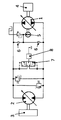
- FIG. 1 a closed hydraulic circuit according to the present invention is shown schematically.
- a hydraulic pump 1 is provided, which promotes hydraulic fluid and drives the hydraulic motor 2. Its outlet oil quantity is returned directly to the pump 1.
- volumetric losses in the closed hydraulic circuit are compensated by means of a feed pump 5, which is connected via check valves 6 to the two load sides A and B of the closed hydraulic circuit.
- this is a hydraulic circuit with two directions of flow, so that depending on the pumping direction of the pump 1, either the load side A or the load side B works as a high pressure side while the other side works as a low pressure side.
- the pump 1 and / or the motor 2 may be designed as an adjustment.
- the pump 1 may be driven by a motor 4, while the hydraulic motor 2 drives a device 3.
- the shuttle valve 7 is now the lower load pressure (usually corresponds to the feed pressure) of a flushing device 8 according to the invention fed tossenspeisen a portion of the hot oil from the circulation, and thus to avoid overheating.
- the flushing device 8 according to the invention is in FIG. 1 drawn as a separate unit to the shuttle valve 7, but can also be combined with this.
- the shuttle valve 7 is designed so that from a certain Pressure difference between the load side A and the load side B uses a purge function and a certain Ausspeisefluidstrom is discharged.
- the flushing device 8 is now designed so that this Ausspeisefluidstrom depends on the temperature of the hydraulic fluid. As a result, a needs-based flushing is achieved.
- the present invention makes use of the fact that the viscosity of the hydraulic fluid decreases with increasing temperature. According to the invention, therefore, the Ausspeisefluidstrom fail by means of a viscosity-dependent throttle as a function of the temperature variable, so that when hot oil much Ausspeisefluidstrom obtained, and thus the temperature can be reduced in a closed circuit.
- the length of the gap is more than twice as large as its height, advantageously more than five times and further advantageously more than ten times. If a bore is used, its length is advantageously also more than twice as large as its diameter, furthermore advantageously more than five times and furthermore advantageously more than ten times.
- Such a viscosity-dependent throttle point can be arranged in a first variant according to the invention as a flushing device 8 behind the shuttle valve 7.
- the throttle point must only be dimensioned so that sufficient Ausspeisefluidstrom is generated.
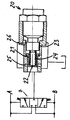
- FIG. 2a An embodiment of a flushing device according to the invention, in which a two-stage flush valve 20 is used instead, is shown in FIG. 2a.
- This comprises a main piston 21 with a central throttle 22.
- the main piston 21 determines the Ausspeisefluidstrom by depending on its position, the connection between the input side of the valve and the main opening 25, which leads to the tank, opens or closes.
- the piston 21 is biased by a spring 24 against the pressure on the input side.
- the fluid is guided to the viscosity-dependent measuring point 23, which is designed according to the invention as a viscosity-dependent throttle.
- the measuring point 23 can be designed as a long cylindrical annular gap, as shown in the exemplary embodiment.
- the geometric conditions are ideally such that the diameter of the cylindrical annular gap is in the range of the gap length.
- a long calibration bore could also be used, wherein advantageously the length of the calibration bore corresponds at least five times to the diameter of the bore.
- the lower load pressure in the closed circuit is always supplied to the purge valve 20 via the shuttle valve 7.
- the alternative embodiment described above without a control stage could be constructed such that in the apparatus shown in FIG. 2a the main piston 21, the spring 24 and the main opening 25 are dispensed with.
- the measuring point 23 would then have to be designed so that the same amount of outflow fluid flow is generated.
- the maximum Ausspeisefluidstrom could then be limited by means of the relief hole 26.
- FIG. 2 b shows a further embodiment with a two-stage valve, in which the main stage and the measuring point are designed as in the variant shown in FIG. 2 a.
- a pressure compensation is provided.
- a throttle piston 29 is provided, which controls the volume flow from the measuring point 23 to the relief bore 28.
- the inlet pressure Px at the flush valve 20 is guided to the rear side of the throttle piston 29, which is biased by a spring 27 against this pressure.
- the throttle piston 29 thus generates in combination with the spring 27, a throttling of the control flow relative to the relief bore 28.
- the pressure difference across the measuring point 23 regardless of the level of the inlet pressure Px be kept constant.
- the advantage is that no variation of the Ausspeisefluidstroms is caused by feed pressure variations.
- An annular gap acting according to the invention as a viscosity-dependent throttle can, as shown in FIGS. 2 a and 2 b, be provided by a cylinder which is inserted into a correspondingly larger hollow cylinder, for example screwed in.
- the throttle piston 29 is arranged in a bore within this cylinder, where the control flow from the measuring point 23 is guided through the cylinder wall into the bore in the interior of the cylinder via a bore 26.
- FIGS. 2a and 2b respectively, embodiments of a flushing device according to the invention have been shown, in which the shuttle valve and the flushing valve have been designed separately, the present invention also includes such Flushing devices in which the shuttle valve is combined with the flush valve formed.
- the viscosity-dependent throttle can be integrated into the shuttle valve.
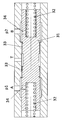
- FIG. 3 an embodiment of such a shuttle valve is shown.
- a piston 31 is provided, which is deflected due to the pressure difference between the sides A and B against the springs 32.
- the low-pressure side is connected to the tank connection T via an annular gap 33 acting as a viscosity-dependent throttle, so that a temperature-dependent outflow fluid flow is established.
- This embodiment has the further advantage that with increasing pressure difference in the closed circuit, the piston 31 deflects more and more against the springs 32. As a result, the effective annular gap 33 becomes shorter and the Ausspeisefluidstrom increases inversely proportional to the length of the annular gap 33 at. Furthermore, an attenuation of the movement of the piston 31 can be provided. For example, the Ausspeisefluidstromzuworm be delayed in time over the bore 34 at sudden load pressure increase. As a result, supply pressure drops in the closed circuit can be prevented. Basically, however, more exit fluid flow is generated at high load pressures. Furthermore, the tank line T can be used as a limitation of the maximum Ausspeisefluidstroms, z. B. by combination with a limiting nozzle.
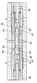
- the shuttle valve is combined with the temperature-dependent rinsing function according to the invention, the basic structure of the shuttle valve already being used with regard to FIG. 3 explained principle corresponds. However, a switching stage is additionally integrated, which shuts off the purge below a certain minimum value on the low pressure side.
- a piston 47 is provided, which deflects due to a pressure difference between A and B against the springs 46 and thereby the respective low pressure side connects to the tank port T via the corresponding annular gap 44.
- the piston 47 is now designed as a bush, in each of which pilot pistons 41 and 41 'are provided for the sides B and A.
- the respective connection point 43 is opened, so that hydraulic fluid can flow from the measuring point 44 via the connection point 43 through the interior of the pilot piston 49 and the interior of the bushing 47 to the tank connection T.
- the bushing 47 may be damped to achieve a time delay, similar to the bore 34 in FIG Fig. 3 ,
- the output fluid flow is thus adjusted to be viscosity-dependent in the case of the embodiments that are hydraulically adapted to the requirements shown here.
- a viscosity-dependent Ausspeisefluidstromgener mich can optionally be combined with the already described functions such as a change function, a switching function, a load pressure dependence, a damping and a setting of a maximum Ausspeisefluidstroms.
- the outfeed can also be implemented via a temperature measurement and a correspondingly actuated control valve.
- a control loop with temperature measurement can be provided.
- FIG. 5 a corresponding embodiment of a hydraulic circuit is shown.
- the circuit temperature is measured at a suitable point in a closed circuit by means of a temperature sensor 51.
- this measurement could optionally take place after the shuttle valve 7.
- an actuator 54 is now driven depending on the temperature in the circuit, which extracts an adjustable Ausspeisefluidstrom from the circulation.
- a shuttle valve 43 can be connected upstream, or the actuator 54 may already be equipped with the change function.
- valve types / systems are conceivable, for example:
- a pressure reducing or reducing valve can be used, which can flow off fluid with variable pressure via a diaphragm.
- a valve is then combined with a shuttle valve.
- a 2-way proportional flow control valve can be used, which also serves as a shuttle valve and over which the Ausspeisefluidstrom can be adjusted.
- the electronic control also gives the possibility to integrate other monitoring and control functions.
- at least one pressure sensor for the pressure in the hydraulic circuit can be provided, advantageously one pressure sensor for the side A and the side B.
- the electronic control 52 monitors the feed pressure level in order to switch off the purging when the feed pressure level drops. As a result, the entire amount of food for the circulation filling is available.
- the flushing devices of the present invention are advantageously used in a hydraulic system with a feed pump 5 designed as a variable displacement pump.
- a feed pump 5 designed as a variable displacement pump.
- such a feed pump can operate as required and, for example, be designed as a pressure regulator.
- a needs-based and thus energy-saving feed is realized.
Landscapes
- Engineering & Computer Science (AREA)
- Physics & Mathematics (AREA)
- Fluid Mechanics (AREA)
- Mechanical Engineering (AREA)
- General Engineering & Computer Science (AREA)
- Chemical & Material Sciences (AREA)
- Analytical Chemistry (AREA)
- Fluid-Pressure Circuits (AREA)
Abstract
Description
- Die vorliegende Erfindung betrifft ein Hydrauliksystem mit einem geschlossenen hydraulischen Kreislauf aus Hydraulikpumpe und Hydraulikmotor, mit einer Speisepumpe zum Ausgleich von Volumenverlusten im geschlossenen Kreislauf und mit einer Spülvorrichtung zum Ausspeisen eines Teiles des Hydraulikfluides aus dem geschlossenen Kreislauf.
- In einem geschlossenen Hydrauliksystem fördert die Hydraulikpumpe Fluid und treibt damit den Hydraulikmotor an. Dessen Austrittsölmenge wird direkt wieder der Hydraulikpumpe zurückgeführt. Die volumetrischen Verluste werden mittels der Speisepumpe kompensiert. Die Spülvorrichtung speist einen Teil des Öls aus dem Kreislauf aus, um eine Überhitzung zu vermeiden.
- Im Stand der Technik werden dabei üblicherweise Spülventile eingesetzt, welche als konstante Systeme ausgebildet sind und ab einer bestimmten Druckdifferenz zwischen den beiden Seiten des Hydraulikkreislaufes schlagartig einen konstanten Ausspeisefluidstrom ausspeisen.
- Aufgabe der vorliegenden Erfindung ist es, eine verbesserte Spülvorrichtung für ein solches Hydrauliksystem zur Verfügung zu stellen.
- Erfindungsgemäß wird diese Aufgabe durch ein Hydrauliksystem gemäß Anspruch 1 bzw. eine Spülvorrichtung gemäß Anspruch 14 gelöst.
- Das erfindungsgemäße Hydrauliksystem weist einen geschlossenen hydraulischen Kreislauf aus Hydraulikpumpe und Hydraulikmotor auf, wobei eine Speisepumpe zum Ausgleich von Volumenverlusten im geschlossenen Kreislauf und eine Spülvorrichtung zum Ausspeisen eines Teiles des Hydraulikfluides aus dem geschlossenen Kreislauf vorgesehen sind. Erfindungsgemäß ist die Spülvorrichtung dabei so ausgeführt, dass der Ausspeise-Fluidstrom von der Temperatur des Hydraulikfluides abhängt. Die vorliegende Erfindung erlaubt so eine bedarfsgerechte Spülung des Hydraulikfluids im geschlossenen Kreislauf, und damit einen effizienteren Betrieb des Hydrauliksystems. Insbesondere wird der Ausspeise-Fluidstrom dabei einem Hydraulik-Kühler und/oder dem Tank zugeführt.
- Vorteilhafterweise erhöht sich dabei bei steigender Temperatur des Hydraulikfluides der Ausspeise-Fluidstrom, um so bedarfsgerecht eine Überhitzung des Hydraulikfluides im geschlossenen Kreislauf zu verhindern. Umgekehrt kann bei einer niedrigen Temperatur des Hydraulikfluides des Ausspeisefluidstroms entsprechend gering sein.
- In einer ersten vorteilhaften Ausgestaltung der vorliegenden Erfindung weist die Spülvorrichtung eine viskositätsabhängige Drossel auf. Die vorliegende Erfindung macht sich dabei die physikalische Tatsache zu nutze, dass sich die Viskosität des Hydraulikfluides bei steigender Temperatur verringert. Damit erhöht sich bei steigender Temperatur des Hydraulikfluids der Durchfluss durch die viskositätsabhängige Drossel. Erfindungsgemäß fällt so die Ausspeisefluidstrom durch den Einsatz einer viskositätsabhängigen Drossel variabel aus, wobei bei heißem Öl viel Ausspeisefluidstrom anfällt, und damit die Temperatur im geschlossenen Kreislauf gesenkt wird.
- Die Verwendung einer viskositätsabhängigen Drossel hat neben der temperaturabhängigen Spülung den weiteren Vorteil, dass der Ausspeisefluidstrom sich bei einem Einschalten der Spülvorrichtung nicht schlagartig ändert, sondern gedämpft ansteigt. Hierdurch können Druckeinbrüche auf der Niederdruckseite verhindert werden.
- Die viskositätsabhängige Drossel kann dabei durch eine Bohrung oder einen Spalt gebildet werden. Insbesondere kann dabei ein Ringspalt eingesetzt werden.
- Vorteilhafterweise ist die Länge der Bohrung bzw. des Spaltes mehr als doppelt so groß wie der Durchmesser der Bohrung bzw. die Höhe des Spaltes. Weiterhin vorteilhafterweise beträgt die Länge der Bohrung bzw. des Spaltes dabei mehr als das dreifache, weiterhin vorteilhafterweise mehr als das fünffache des Durchmessers der Bohrung bzw. der Höhe des Spaltes. Hierdurch kann eine entsprechende Abhängigkeit der Durchflussmenge durch die Drossel von der Viskosität des Hydraulikfluids erreicht werden.
- Besonders vorteilhaft ist die Drossel als ein zylindrischer Ringspalt ausgeführt. Insbesondere kann dabei der Innendurchmesser des Zylinders zwischen dem 0,5-fachen und 2-fachen der Spaltlänge betragen, weiterhin vorteilhafterweise zwischen dem 0,8-fachen und 1,2-fachen der Spaltlänge.
- In einer ersten Ausführungsform kann der Ausspeise-Fluidstrom direkt durch die viskositätsabhängige Drossel fließen, und so in Abhängigkeit von seiner Viskosität direkt durch die Drossel angesteuert werden.
- In einer zweiten Ausführungsform umfasst die Spülvorrichtung dagegen ein zwei-stufiges Ventil mit einem Hauptkolben zur Ansteuerung des Ausspeise-Fluidstroms und einer Steuerstufe, wobei die viskositätsabhängige Drossel in der Steuerstufe angeordnet ist. Die durch die sinkende Viskosität zunehmende Menge an der Drossel sorgt so für einen höheren Steuerstrom, durch welchen der Hauptkolben ebenfalls entsprechend ausgelenkt wird, um einen erhöhten Ausspeisefluidstrom zu erzeugen.
- Weiterhin kann vorgesehen sein, dass zur Einstellung einer definierten Druckdifferenz über die viskositätsabhängige Drossel ein Drosselkolben vorgesehen ist, welcher mit dem Eingangsdruck der Spülvorrichtung beaufschlagt ist. Vorteilhafterweise ist der Drosselkolben dabei hinter der viskositätsabhängigen Drossel angeordnet und steuert den Fluss des Hydraulikfluids zum Tank.
- Insbesondere kann dabei der Drosselkolben ein Drucksteuerventil bilden, welches auf der einen Seite mit dem Druck auf der Eingangsseite der Spülvorrichtung beaufschlagt wird und auf der anderen Seite mit dem Druck hinter der viskositätsabhängigen Drossel. Insbesondere kann ein solcher Drosselkolben vorgesehen werden, wenn die viskositätsabhängige Drossel in der Steuerstufe eines zweistufigen Ventils angeordnet ist.
- Vorteilhafterweise ist bei der vorliegenden Erfindung weiterhin ein Wechselventil vorgesehen, durch welches der Ausspeise-Fluidstrom immer aus der Seite des Hydraulikkreislaufs entnommen wird, an welcher der tiefere Lastdruck anliegt. Dieser tiefere Lastdruck entspricht dabei in der Regel dem Speisedruck.
- Erfindungsgemäß können dabei das Wechselventil und die viskositätsabhängige Drossel separat ausgeführt sein. Insbesondere kann dabei ein Wechselventil mit der viskositätsabhängigen Drossel oder einem zweistufigen Ventil, in dessen Steuerstufe die viskositätsabhängige Drossel angeordnet ist, in Reihe geschaltet werden.
- Alternativ kann die viskositätsabhängige Drossel in das Schaltventil integriert sein. Vorteilhafterweise weist das Schaltventil dabei einen Kolben auf, und ist so ausgeführt, dass der Kolben auf gegenüberliegenden Seiten mit dem Druck der beiden Seiten des geschlossenen Hydraulikkreislaufs beaufschlagt wird. Je nach Druckverhältnissen gibt dabei der Kolben die Verbindung zwischen der einen oder der anderen Seite mit dem Tank frei, wobei der Kolben jeweils die Niederdruckseite mit dem Tank verbindet.
- Vorteilhafterweise erfolgt die Verbindung zwischen der Niederdruckseite und dem Tank dabei jeweils über eine viskositätsabhängige Drossel, welche damit erfindungsgemäß den Ausspeisefluidstrom in Abhängigkeit von der Temperatur des Hydraulikfluids einstellt. Vorteilhafterweise sind dabei zwei jeweils einer Seite des geschlossenen Hydraulikkreislaufs zugeordnete viskositätsabhängige Drosseln vorgesehen.
- Weiterhin kann im Kolben mindestens ein Pilotkolben vorgesehen sein, welcher einen Spülstrom unterhalb eines gewissen Mindestdruckes auf der Niederdruckseite verhindert. Insbesondere kann der Pilotkolben dabei gegen eine Federkraft vorgespannt sein, welche durch den Druck auf der Niederdruckseite erst überwunden werden muss, um einen Spülstrom zu ermöglichen.
- Weiterhin kann erfindungsgemäß vorgesehen sein, dass die Länge der viskositätsabhängigen Drossel durch die Druckdifferenz zwischen der Hoch- und der Niederdruckseite eingestellt wird. Vorteilhafterweise sinkt dabei die Länge der Drossel bei einer Erhöhung der Druckdifferenz, so dass bei einer höheren Druckdifferenz ein entsprechend höherer Volumenstrom erreicht wird.
- Ist die Drossel wie oben näher beschrieben in ein Schaltventil integriert, so wird die viskositätsabhängige Drossel vorteilhafterweise durch einen Ringspalt zwischen dem Kolben und einem Ventilgehäuse gebildet, wobei sich die Länge der viskositätsabhängigen Drossel bei einer Verschiebung des Kolbens ändert.
- In einer weiteren Ausführungsform der vorliegenden Erfindung weist die Spülvorrichtung einen Temperatursensor auf, über welchen ein Steuerventil zum Ansteuern des Ausspeise-Fluidstroms angesteuert wird. Dies ermöglicht eine noch flexiblere Ansteuerung des Ausspeise-Fluidstroms anhand der Temperatur. Insbesondere kann dabei der Ausspeise-Fluidstrom bei steigender Temperatur erhöht und bei sinkender Temperatur verringert werden. Vorteilhafterweise wird dabei die Temperatur des Hydraulikfluids durch die Spülvorrichtung auf eine vorgegebene Temperatur geregelt. Insbesondere kann diese Temperatur einstellbar sein.
- Vorteilhafterweise wird dabei eine elektronische Steuerung zur Auswertung der Daten des Temperatursensors und zur Ansteuerung des Steuerventils eingesetzt.
- Erfindungsgemäß kann weiter mindestens ein Drucksensor vorgesehen sein, wobei der Ausspeise-Fluidstrom auf Grundlage der Daten des Drucksensors angesteuert wird.
- Vorteilhafterweise wird dabei der Ausspeise-Fluidstrom in Abhängigkeit von der Druckdifferenz zwischen Hoch- und Niederdruckseite angesteuert. Insbesondere kann dabei der Ausspeise-Fluidstrom bei steigender Druckdifferenz erhöht werden.
- Weiterhin vorteilhafterweise kann der Ausspeise-Fluidstrom in Abhängigkeit von dem Druck auf der Niederdruckseite angesteuert werden. Insbesondere kann dabei vorgesehen sein, dass die Ausspeisefunktion erst bei einem gewissen Mindestdruck auf der Niederdruckseite einsetzt. Hierdurch kann das Auftreten von plötzlichen Druckabfällen durch das Einsetzen der Ausspeisung verhindert werden.
- Erfindungsgemäß kann beispielsweise ein Druckreduzierventil in Kombination mit einer Blende oder ein Proportional-Stromregelventil als Steuerventil vorgesehen sein. Auch hier kann das Steuerventil für die Ansteuerung des Ausspeise-Fluidstroms separat zu einem Schaltventil ausgeführt sein oder mit diesem kombiniert werden. Insbesondere kann dabei ein 2-Wege Proportional-Stromregelventil vorgesehen sein, welches gleichzeitig als Schalt- und Steuerventil dient.
- Besonders bevorzugt kommt die vorliegende Erfindung bei einem Hydrauliksystem zum Einsatz, dessen Speisepumpe als Verstellpumpe ausgeführt ist. Hierdurch kann die Verlustleistung durch die Einspeisepumpe reduziert werden, wobei durch die bedarfsgerechte Ausspeisung des Hydraulikfluids gemäß der vorliegenden Erfindung die verbrauchte Speisemenge und damit die Verlustleistung gesenkt wird.
- Vorteilhafterweise wird dabei die Speisepumpe bedarfsgerecht angesteuert. Insbesondere kann die Speisepumpe dabei als Druckregler ausgebildet sein.
- Neben dem Hydrauliksystem umfasst die vorliegende Erfindung weiterhin eine Spülvorrichtung für ein Hydrauliksystem, wie sie oben beschrieben wurde.
- Insbesondere umfasst die Spülvorrichtung dabei eine viskositätsabhängige Drossel. Weiterhin vorteilhafterweise ist die Spülvorrichtung dabei so aufgebaut, wie dies oben beschrieben wurde.
- Alternativ kann die erfindungsgemäße Spülvorrichtung einen Temperatursensor und ein Steuerventil aufweisen, welches in Abhängigkeit von der durch den Temperatursensor gemessenen Temperatur angesteuert wird.
- Weiterhin kann die erfindungsgemäße Spülvorrichtung ein Wechselventil umfassen. Das Wechselventil kann dabei ein separates Element bilden oder mit einer der übrigen Komponenten der Spülvorrichtung kombiniert sein, insbesondere der viskositätsabhängigen Drossel oder dem Steuerventil. Vorteilhafte Ausgestaltungen sind dabei ebenfalls oben bereits beschrieben.
- Die vorliegende Erfindung umfasst weiterhin ein Verfahren zum Betrieb eines Hydrauliksystems mit einem geschlossenen hydraulischen Kreislauf aus Hydraulikpumpe und Hydraulikmotor mit einer Spülvorrichtung zum Ausspeisen eines Teiles des Hydraulikfluides aus dem geschlossenen Kreislauf. Das erfindungsgemäße Verfahren ist dadurch gekennzeichnet, dass der Ausspeise-Fluidstrom in Abhängigkeit von der Temperatur des Hydraulikfluides verändert wird. Vorteilhafterweise wird dabei bei steigender Temperatur der Ausspeise-Fluidstrom erhöht und/oder bei sinkender Temperatur der Ausspeise-Fluidstrom verringert.
- Vorteilhafterweise dient das erfindungsgemäße Verfahren dabei zum Betrieb eines Hydrauliksystems, wie es oben beschrieben wurde. Weiterhin vorteilhafterweise wird das Hydrauliksystem dabei so betrieben, wie dies ebenfalls oben bereits dargestellt wurde.
- Die vorliegende Erfindung ermöglicht über die Berücksichtigung der Kreislauftemperatur eine bedarfsgerechte Spülung. Hierdurch wird die energetische Auslegung der Spülfunktion verbessert. Weiterhin wird ein schlagartiges Einschalten der Spülung verhindert, welches ansonsten wie im Stand der Technik zu Speisedruckabfällen führen würde.
- Besonders vorteilhaft wird die vorliegende Erfindung dabei mit einer variablen Einspeisung kombiniert, so dass eine entsprechend Energieeinsparung realisiert werden kann.
- Die vorliegende Erfindung wird nun anhand von Ausführungsbeispielen sowie Zeichnungen näher dargestellt. Dabei zeigen:
- Figur 1:
- ein Ausführungsbeispiel eines erfindungsgemäßen Hydraulikkreislaufs,
- Figur 2a:
- ein erstes Ausführungsbeispiel einer erfindungsgemäßen Spülvorrichtung mit einem zweistufigen Spülventil,
- Figur 2b:
- ein zweites Ausführungsbeispiel einer erfindungsgemäßen Spülvorrichtung mit einem zweistufigen Spülventil,
- Figur 3:
- ein Ausführungsbeispiel einer erfindungsgemäßen Spülvorrichtung, welche mit einem Wechselventil kombiniert ist,
- Figur 4:
- ein Ausführungsbeispiel einer erfindungsgemäßen Spülvorrichtung, welche ebenfalls mit einem Wechselventil kombiniert und mit einem Pilotkolben ausgestattet ist und
- Figur 5:
- einen Hydraulikkreislauf mit einem Ausführungsbeispiel einer erfindungsgemäßen Spülvorrichtung, welche eine elektronische Temperaturregelung vorsieht.
- In
Figur 1 ist ein geschlossener Hydraulikkreislauf gemäß der vorliegenden Erfindung schematisch dargestellt. Dabei ist eine Hydraulikpumpe 1 vorgesehen, welche Hydraulikfluid fördert und den Hydraulikmotor 2 antreibt. Dessen Austrittsölmenge wird direkt wieder der Pumpe 1 zurückgeführt. - Volumentrische Verluste im geschlossenen Hydraulikkreislauf werden mittels einer Speisepumpe 5 kompensiert, welche über Rückschlagventile 6 mit den beiden Lastseiten A und B des geschlossenen Hydraulikkreislaufs in Verbindung steht.
- Dabei handelt es sich erfindungsgemäß bei dem vorliegenden geschlossenen Hydraulikkreislauf um einen Hydraulikkreislauf mit zwei Flußrichtungen, so dass je nach Pumprichtung der Pumpe 1 entweder die Lastseite A oder die Lastseite B als Hochdruckseite arbeitet, während die andere Seite als Niederdruckseite arbeitet.
- Je nach Ausführungsbeispiel können die Pumpe 1 und/oder der Motor 2 als Verstelleinheit ausgeführt sein. Weiterhin kann die Pumpe 1 über einen Motor 4 angetrieben sein, während der Hydraulikmotor 2 eine Vorrichtung 3 antreibt.
- Über das Wechselventil 7 wird nun der tiefere Lastdruck (entspricht in der Regel dem Speisedruck) einer erfindungsgemäßen Spülvorrichtung 8 zugeführt, um einen Teil des heißen Öls aus dem Kreislauf auszuspeisen, und so eine Überhitzung zu vermeiden. Die erfindungsgemäße Spülvorrichtung 8 ist dabei in
Figur 1 als separate Einheit zu dem Wechselventil 7 eingezeichnet, kann jedoch ebenso mit diesem kombiniert werden. Das Wechselventil 7 ist dabei so ausgeführt, dass ab einer bestimmten Druckdifferenz zwischen der Lastseite A und der Lastseite B eine Spülfunktion einsetzt und ein gewisser Ausspeisefluidstrom abgeführt wird. - Erfindungsgemäß ist die Spülvorrichtung 8 nun so ausgeführt, dass dieser Ausspeisefluidstrom von der Temperatur des Hydraulikfluides abhängt. Hierdurch wird eine bedarfsgerechte Spülung erreicht.
- In einer ersten Variante macht sich die vorliegende Erfindung die Tatsache zu nutze, dass die Viskosität des Hydraulikfluides mit steigender Temperatur absinkt. Erfindungsgemäß kann daher der Ausspeisefluidstrom mittels einer viskositätsabhängigen Drossel in Abhängigkeit von der Temperatur variabel ausfallen, so dass bei heißem Öl viel Ausspeisefluidstrom anfällt, und so die Temperatur im geschlossenen Kreislauf gesenkt werden kann.
- Hierbei wird folgende physikalische Eigenschaft einer viskositätsabhängigen Spaltdrossel verwendet:

QSpalt = Volumenstrom durch den Spalt, hSpalt = Spalthöhe, ISpalt = Spaltlänge, v = kinematische Viskosität des Fluides - Sinkt daher mit steigender Temperatur die Viskosität des Fluides, erhöht sich entsprechend der Volumenstrom durch den Spalt. Ähnliche Verhältnisse gelten auch für lange Kalibrierbohrungen.
- Vorteilhafterweise ist dabei die Länge des Spaltes mehr als zweimal so groß wie dessen Höhe, vorteilhafterweise mehr als fünfmal und weiterhin vorteilhafterweise mehr als zehnmal. Wird eine Bohrung eingesetzt, ist deren Länge vorteilhafterweise ebenfalls mehr als doppelt so groß wie deren Durchmesser, weiterhin vorteilhafterweise mehr als fünfmal und weiterhin vorteilhafterweise mehr als zehnmal.
- Eine solche viskositätsabhängige Drosselstelle kann in einer ersten Variante erfindungsgemäß als Spülvorrichtung 8 hinter dem Wechselventil 7 angeordnet werden. Die Drosselstelle muss dabei lediglich so dimensioniert werden, dass genügend Ausspeisefluidstrom erzeugt wird.
- Ein Ausführungsbeispiel einer erfindungsgemäßen Spülvorrichtung, bei welcher stattdessen ein zwei-stufiges Spülventil 20 zum Einsatz kommt, ist in Figur 2a gezeigt. Dieses umfasst einen Hauptkolben 21 mit einer zentralen Drosselstelle 22. Der Hauptkolben 21 bestimmt den Ausspeisefluidstrom, indem er je nach seiner Stellung die Verbindung zwischen der Eingangsseite des Ventils und der Hauptöffnung 25, welche zum Tank führt, öffnet bzw. schließt. Der Kolben 21 wird dabei durch eine Feder 24 gegen den Druck an der Eingangsseite vorgespannt.
- Durch die Drosselstelle 22 im Hauptkolben 21 wird das Fluid zur viskositätsabhängigen Messstelle 23 geführt, welche erfindungsgemäß als viskositätsabhängige Drossel ausgeführt ist. Insbesondere kann die Messstelle 23 dabei als langer zylindrischer Ringspalt ausgeführt sein, wie dies im Ausführungsbeispiel dargestellt ist. Die geometrischen Verhältnisse liegen dabei idealerweise so, dass der Durchmesser des zylindrischen Ringspaltes im Bereich der Spaltlänge liegt. Alternativ könnte jedoch auch eine lange Kalibrierbohrung eingesetzt werden, wobei vorteilhafterweise die Länge der Kalibrierbohrung mindestens fünfmal dem Durchmesser der Bohrung entspricht.
- Eine durch sinkende Viskosität (entspricht steigender Öltemperatur) zunehmende Menge an der Messstelle 23 in Richtung der Entlastungsbohrung 26 erhöht die Druckdifferenz an der Drosselstelle 22 und lenkt den Hauptkolben 22 gegen die Feder 24 aus. Dadurch wird die Hauptöffnung 25 immer größer und mehr Ausspeisefluidstrom fällt an. Die Hauptöffnung 25 kann dabei so ausgebildet sein, dass ein maximaler Ausspeisefluidstrom nicht überschritten wird.
- Dabei wird über das Wechselventil 7 immer der niedrigere Lastdruck im geschlossenen Kreislauf dem Spülventil 20 zugeführt.
- Die bereits oben beschriebene alternative Ausführungsform ohne eine Steuerstufe könnte so aufgebaut sein, dass bei der in Figur 2a gezeigten Vorrichtung auf den Hauptkolben 21, die Feder 24 und die Hauptöffnung 25 verzichtet wird. Die Messstelle 23 müsste dann so ausgeführt sein, dass gleich genügend Ausspeisefluidstrom erzeugt wird. Der maximale Ausspeisefluidstrom könnte dann mittels der Entlastungsbohrung 26 limitiert werden.
- In Figur 2b ist nun eine weitere Ausführungsform mit einem zweistufigen Ventil dargestellt, bei welchem die Hauptstufe und die Messstelle wie bei der in Figur 2a gezeigten Variante ausgeführt ist. Zusätzlich ist jedoch eine Druckkompensation vorgesehen. Dabei ist ein Drosselkolben 29 vorgesehen, welcher den Volumenstrom von der Messstelle 23 zur Entlastungsbohrung 28 ansteuert. Dabei wird der Eingangsdruck Px am Spülventil 20 auf die Rückseite des Drosselkolbens 29 geführt, welcher über eine Feder 27 gegen diesen Druck vorgespannt ist. Der Drosselkolben 29 erzeugt so in Kombination mit der Feder 27 eine Drosselung des Steuerstroms gegenüber der Entlastungsbohrung 28. Hierdurch kann die Druckdifferenz über die Messstelle 23 unabhängig vom Niveau des Eingangsdruckes Px konstant gehalten werden. Der Vorteil besteht darin, dass durch Speisedruckvariationen keine Variation des Ausspeisefluidstroms hervorgerufen wird.
- Ein erfindungsgemäß als viskositätsabhängige Drossel wirkender Ringspalt kann dabei, wie in Figuren 2a und 2b gezeigt, durch einen Zylinder zur Verfügung gestellt werden, welcher in einen entsprechend größeren Hohlzylinder eingefügt wird, bspw. eingeschraubt. Bei der in Figur 2b gezeigten Variante ist dabei der Drosselkolben 29 in einer Bohrung innerhalb dieses Zylinders angeordnet, wobei dort der Steuerstrom von der Messstelle 23 über eine Bohrung 26 durch die Zylinderwand in die Bohrung im Inneren des Zylinders geführt wird.
- Während in Figuren 2a und 2b jeweils Ausführungen einer erfindungsgemäßen Spülvorrichtung gezeigt wurden, bei welchen das Wechselventil und das Spülventil separat ausgeführt wurden, umfasst die vorliegende Erfindung weiterhin auch solche Spülvorrichtungen, bei welchen das Wechselventil mit dem Spülventil kombiniert ausgebildet ist. Insbesondere kann dabei die viskositätsabhängige Drossel in das Wechselventil integriert werden.
- In
Figur 3 ist ein Ausführungsbeispiel eines solchen Wechselventils gezeigt. Dabei ist ein Kolben 31 vorgesehen, welcher aufgrund der Druckdifferenz zwischen den Seiten A und B gegen die Federn 32 ausgelenkt wird. Hierdurch wird jeweils die Niederdruckseite über einen als viskositätsabhängige Drossel wirkenden Ringspalt 33 mit dem Tankanschluss T verbunden, so dass sich ein temperaturabhängiger Ausspeisefluidstrom einstellt. - Diese Ausführungsform hat den weiteren Vorteil, dass bei steigender Druckdifferenz im geschlossenen Kreislauf der Kolben 31 immer mehr gegen die Federn 32 auslenkt. Hierdurch wird der wirksame Ringspalt 33 kürzer und der Ausspeisefluidstrom steigt umgekehrt proportional zur Länge des Ringspaltes 33 an. Weiterhin kann eine Dämpfung der Bewegung des Kolbens 31 vorgesehen werden. Beispielsweise kann dabei über die Bohrung 34 bei schlagartigem Lastdruckanstieg die Ausspeisefluidstromzunahme zeitlich verzögert werden. Hierdurch können Speisedruckeinbrüche im geschlossenen Kreislauf verhindert werden. Grundsätzlich wird jedoch bei hohen Lastdrücken mehr Ausspeisefluidstrom erzeugt. Weiterhin kann die Tankleitung T als Begrenzung des maximalen Ausspeisefluidstroms verwendet werden, z. B. durch Kombination mit einer Begrenzungsdüse.
- Auch bei der in
Figur 4 gezeigten Ausführungsform wird das Wechselventil mit der erfindungsgemäßen temperaturabhängigen Spülfunktion kombiniert, wobei der grundsätzliche Aufbau des Wechselventils dem bereits im Hinblick aufFigur 3 erläuterten Prinzip entspricht. Jedoch ist zusätzlich eine Schaltstufe integriert, welche die Spülung unterhalb eines bestimmten Minimalwerts auf der Niederdruckseite abschaltet. - Dabei ist wiederum ein Kolben 47 vorgesehen, welcher aufgrund einer Druckdifferenz zwischen A und B gegen die Federn 46 auslenkt und dabei die jeweilige Niederdruckseite über den entsprechenden Ringspalt 44 mit dem Tankanschluss T verbindet.
- Der Kolben 47 ist nun aber als eine Buchse ausgeführt, in welcher jeweils Pilotkolben 41 bzw. 41' für die Seiten B und A vorgesehen sind. Die Pilotkolben 41 und 41' sind dabei über eine mittig angeordnete Feder 45 jeweils gegen den Druck auf der Seite A bzw. B vorgespannt und verschließen die Verbindungsstelle 43 zu den jeweiligen Ringspalten 44 über eine Schaltkante, wenn der Druck auf der jeweiligen Niederdruckseite unter einen entsprechenden Minimaldruck fällt. Steigt der Druck dagegen, wird die jeweilige Verbindungsstelle 43 aufgesteuert, so dass Hydraulikfluid von der Messstelle 44 über die Verbindungsstelle 43 durch das Innere des Pilotkolbens 49 und das Innere der Buchse 47 zum Tankanschluss T fließen kann. Die Buchse 47 kann zum Erreichen eines Zeitverzugs gedämpft werden, ähnlich wie die Bohrung 34 in
Fig. 3 . - Im folgenden soll die Funktionsweise des Wechselventils in
Fig. 4 noch einmal zusammenfassend für die Situation, in welcher die Seite B die Hochdruckseite bildet, während die Seite A die Niederdruckseite bildet, beschrieben werden: - Durch Druckerhöhung auf der Lastseite B wird der Pilotkolben 41 nach links gegen die Feder 45 bis an einen Anschlag mit der Buchse 47 verschoben. Nun wird die Buchse 47 gegen die Feder 46 ausgelenkt und gibt die viskositätsabhängige Drosselstelle 44 frei. Je höher der Lastdruck in B, desto kürzer ist wiederum die aktive Länge der Drosselstelle 44 und desto höher der Ausspeisefluidstrom. Eine solche Lastdruckabhängigkeit kann dabei wahlweise integriert werden.
- Damit nun eine Druckdifferenz über die Drosselstelle 44 zwischen A und T entstehen kann, muss der Niederdruck in A so groß sein, dass der Pilotkolben 41' gegen die Feder 45 auslenkt und die Schaltkante zur Verbindungsstelle 43 freigibt. Nur dann kann der Ausspeisefluidstrom von A über die Drosselstelle 44 durch die Verbindungsstelle 43 und von dort weiter durch die Zentralbohrung 49 im Pilotkolben 41' nach T fließen. Die Feder 45 verhindert also, dass unterhalb eines gewissen Druckwertes in A die Spülung einsetzt. Dieser Wert liegt beispielsweise zwischen 10 und 30 bar. Diese Zusatzfunktion ist wahlweise kombinierbar.
- Zusammenfassend wird damit bei den vorliegend gezeigten hydraulisch an den Bedarf angepassten Ausführungsformen der Ausspeisefluidstrom viskositätsabhängig eingestellt. Eine solche viskositätsabhängige Ausspeisefluidstromgenerierung kann dabei wahlweise mit den bereits beschriebenen Funktionen wie einer Wechselfunktion, einer Schaltfunktion, einer Lastdruckabhängigkeit, einer Dämpfung und einer Einstellung eines maximalen Ausspeisefluidstroms kombiniert werden.
- Alternativ kann die Ausspeisung auch über eine Temperaturmessung und ein entsprechend angesteuertes Steuerventil implementiert werden. Insbesondere kann dabei ein Regelkreis mit Temperaturmessung vorgesehen sein.
- In
Figur 5 ist ein entsprechendes Ausführungsbeispiel eines Hydraulikkreislaufes gezeigt. Dabei wird an einer geeigneten Stelle im geschlossenen Kreis mittels eines Temperatursensors 51 die Kreislauftemperatur gemessen. Diese Messung könnte jedoch wahlweise auch nach dem Wechselventil 7 stattfinden. Mit Hilfe eines elektronischen Regelkreises ICU (52) wird nun je nach Temperatur im Kreislauf ein Aktuator 54 angesteuert, welcher einen regelbaren Ausspeisefluidstrom aus dem Kreislauf entzieht. Diesem Aktuator kann ein Wechselventil 43 vorgeschaltet werden, oder der Aktuator 54 kann bereits mit der Wechselfunktion ausgestattet sein. - Als Aktuatoren sind dabei beispielsweise folgende Ventiltypen/-systeme denkbar:
- Einerseits kann ein Druckreduzier- oder Minderventil eingesetzt werden, welches mit variablem Druck über eine Blende Fluid abströmen lässt. Vorteilhafterweise wird ein solches Ventil dann mit einem Wechselventil kombiniert.
- Alternativ kann ein 2-Wege-Proportionalstrom-Regelventil eingesetzt werden, welches gleichzeitig als Wechselventil dient und über welches der Ausspeisefluidstrom eingestellt werden kann.
- Die elektronische Steuerung gibt weiterhin die Möglichkeit, andere Überwachungs- und Regelfunktionen zu integrieren. Insbesondere kann dabei mindestens ein Drucksensor für den Druck im Hydraulikkreislauf vorgesehen sein, vorteilhafterweise jeweils ein Drucksensor für die Seite A und die Seite B. Vorteilhafterweise überwacht die elektronische Steuerung 52 dabei das Speisedruckniveau, um bei einem Einbruch des Speisedruckniveaus die Spülung abzuschalten. Hierdurch steht die gesamte Speisemenge für die Kreislaufauffüllung zur Verfügung.
- Die Spülvorrichtungen der vorliegenden Erfindung werden vorteilhafterweise in einem Hydrauliksystem mit einer als Verstellpumpe ausgeführten Einspeisepumpe 5 eingesetzt. Insbesondere kann eine solche Einspeisepumpe bedarfsabhängig arbeiten und beispielsweise als Druckregler ausgebildet sein. Hierdurch wird eine bedarfsgerechte und somit energiesparende Einspeisung realisiert.
- Steht eine derartige Einspeisung zur Verfügung, sollten alle Verbraucher, welche an diesem Speisenetz hängen, optimiert werden. Hierzu gehört auch das Spülsystem des Kreislaufs, wobei durch die bedarfsgerechte und optimierte Spülung gemäß der vorliegenden Erfindung die Speisemenge und damit die Verlustleistung gesenkt werden kann.
Claims (15)
- Hydrauliksystem mit einem geschlossenen hydraulischen Kreislauf aus Hydraulikpumpe (1) und Hydraulikmotor (2), mit einer Speisepumpe (5) zum Ausgleich von Volumenverlusten im geschlossenen Kreislauf und mit einer Spülvorrichtung (8) zum Ausspeisen eines Teiles des Hydraulikfluides aus dem geschlossenen Kreislauf,
dadurch gekennzeichnet,
dass die Spülvorrichtung (8) so ausgeführt ist, dass der Ausspeisefluidstrom von der Temperatur des Hydraulikfluides abhängt. - Hydrauliksystem nach Anspruch 1, wobei die Spülvorrichtung eine viskositätsabhängige Drossel (23, 33, 44) aufweist.
- Hydrauliksystem nach Anspruch 2, wobei die viskositätsabhängige Drossel (23, 33, 44) durch eine Bohrung oder einen Spalt, insbesondere einen Ringspalt, gebildet wird, wobei vorteilhafterweise die Länge der Bohrung bzw. des Spaltes mehr als doppelt so groß wie der Durchmesser der Bohrung bzw. die Höhe des Spaltes ist, vorteilhafterweise mehr als dreimal und weiterhin vorteilhafterweise mehr als fünfmal so groß.
- Hydrauliksystem nach Anspruch 2 oder 3, wobei die Spülvorrichtung ein zwei-stufiges Ventil (20) mit einem Hauptkolben (21) zur Ansteuerung des Ausspeisefluidstroms und eine Steuerstufe umfasst, wobei die viskositätsabhängige Drossel (23) in der Steuerstufe angeordnet ist.
- Hydrauliksystem nach einem der Ansprüche 2 bis 4, wobei zur Einstellung einer definierten Druckdifferenz über die viskositätsabhängige Drossel (23) ein Drosselkolben (29) vorgesehen ist, welcher mit dem Eingangsdruck der Spülvorrichtung beaufschlagt ist, wobei der Drosselkolben (29) vorteilhafterweise hinter der viskositätsabhängigen Drossel (23) angeordnet ist und den Fluß des Hydraulikfluids zum Tank steuert.
- Hydrauliksystem nach einem der vorangegangenen Ansprüche, wobei die viskositätsabhängige Drossel (33, 44) in ein Schaltventil integriert ist, welches jeweils die Niederdruckseite des geschlossenen Hydraulikkreislaufs mit dem Tank verbindet.
- Hydrauliksystem nach Anspruch 6, wobei das Schaltventil einen Kolben (31, 47) aufweist und so ausgeführt ist, dass der Kolben auf gegenüberliegenden Seiten mit dem Druck der beiden Seiten (A,B) des geschlossenen Hydraulikkreislaufs beaufschlagt wird, wobei der Kolben (31, 47) vorteilhafterweise jeweils die Niederdruckseite über eine viskositätsabhängige Drossel (33, 44) mit dem Tank verbindet, wobei vorteilhafterweise zwei jeweils einer Seite des geschlossenen Hydraulikkreislaufs zugeordnete viskositätsabhängige Drosseln (33, 44) vorgesehen sind.
- Hydrauliksystem nach Anspruch 6 oder 7, wobei im Kolben (47) mindestens ein Pilotkolben (41) vorgesehen ist, welcher einen Ausspeisefluidstrom unterhalb eines gewissen Mindestdruckes auf der Niederdruckseite verhindert.
- Hydrauliksystem nach einem der Ansprüche 2 bis 10, wobei die Länge der viskositätsabhängigen Drossel (33, 44) durch die Druckdifferenz zwischen der Hoch- und der Niederdruckseite eingestellt wird, wobei vorteilhafterweise in einem Hydrauliksystem nach Anspruch 7 die viskositätsabhängige Drossel bzw. Drosseln durch einen Ringspalt zwischen dem Kolben (31, 47) und einem Ventilgehäuse gebildet ist oder sind, wobei sich die Länge der viskositätsabhängigen Drossel bei einer Verschiebung des Kolbens ändert.
- Hydrauliksystem nach Anspruch 1, wobei die Spülvorrichtung einen Temperatursensor (51) aufweist, über welchen ein Steuerventil (54) zum Ansteuern des Ausspeisefluidstroms angesteuert wird, wobei vorteilhafterweise eine elektronische Steuerung (52) zur Auswertung der Daten des Temperatursensors (51) und zur Ansteuerung des Steuerventils (54) vorgesehen ist und/oder wobei die Spülvorrichtung die Temperatur des Hydraulikfluids auf eine vorgegebene Temperatur regelt.
- Hydrauliksystem nach Anspruch 10, wobei weiterhin mindestens ein Drucksensor vorgesehen ist, wobei vorteilhafterweise der Ausspeise-Fluidstrom in Abhängigkeit von der Druckdifferenz zwischen Hoch- und Niederdruckseite und/oder in Abhängigkeit des Druckes auf der Niederdruckseite angesteuert wird.
- Hydrauliksystem nach Anspruch 10 oder 11, wobei ein Druckreduzierventil in Kombination mit einer Blende oder ein Proportional-Stromregelventil als Steuerventil (54) vorgesehen ist, wobei vorteilhafterweise ein 2-Wege Proportional-Stromregelventil vorgesehen ist, welches gleichzeitig als Schaltventil dient.
- Hydrauliksystem nach einem der vorangegangenen Ansprüche, wobei die Speisepumpe (5) als Verstellpumpe ausgeführt ist und weiterhin vorteilhafterweise bedarfsgerecht angesteuert wird.
- Spülvorrichtung für ein Hydrauliksystem nach einem der vorangegangenen Ansprüche.
- Verfahren zum Betrieb eines Hydrauliksystems mit einem geschlossenen hydraulischen Kreislauf aus Hydraulikpumpe (1) und Hydraulikmotor (2) und mit einer Spülvorrichtung (8) zum Ausspeisen eines Teiles des Hydraulikfluides aus dem geschlossenen Kreislauf, insbesondere zum Betrieb eines Hydrauliksystems nach einem der vorangegangenen Ansprüche,
dadurch gekennzeichnet,
dass der Ausspeisefluidstrom in Abhängigkeit von der Temperatur des Hydraulikfluides verändert wird, wobei vorteilhafterweise bei steigender Temperatur der Ausspeisfluidstrom erhöht wird.
Applications Claiming Priority (1)
| Application Number | Priority Date | Filing Date | Title |
|---|---|---|---|
| CH00010/12A CH705960A1 (de) | 2012-01-04 | 2012-01-04 | Hydrauliksystem mit temperaturabhängiger Hydraulikfluidleckage. |
Publications (3)
| Publication Number | Publication Date |
|---|---|
| EP2613058A2 true EP2613058A2 (de) | 2013-07-10 |
| EP2613058A3 EP2613058A3 (de) | 2017-05-10 |
| EP2613058B1 EP2613058B1 (de) | 2020-03-11 |
Family
ID=46640521
Family Applications (1)
| Application Number | Title | Priority Date | Filing Date |
|---|---|---|---|
| EP12005536.3A Active EP2613058B1 (de) | 2012-01-04 | 2012-07-30 | Hydrauliksystem |
Country Status (2)
| Country | Link |
|---|---|
| EP (1) | EP2613058B1 (de) |
| CH (1) | CH705960A1 (de) |
Cited By (9)
| Publication number | Priority date | Publication date | Assignee | Title |
|---|---|---|---|---|
| DE102015213936A1 (de) * | 2015-07-23 | 2017-01-26 | Danfoss Power Solutions Gmbh & Co. Ohg | Spüleinrichtung für hydrostatische Vorrichtung |
| US9964130B2 (en) | 2014-03-05 | 2018-05-08 | Bomag Gmbh | Method for operating a hydraulic system of a self-propelled paver, hydraulic system, especially for using the method, and paver with such a hydraulic system |
| CN109469665A (zh) * | 2017-09-07 | 2019-03-15 | 罗伯特·博世有限公司 | 静液的阀装置、具有所述阀装置的静液的传动机构和具有所述传动机构的静液的驱动装置 |
| DE102018208352A1 (de) * | 2018-05-28 | 2019-11-28 | Robert Bosch Gmbh | Hydraulische Spülventilanordnung |
| WO2020110426A1 (ja) * | 2018-11-26 | 2020-06-04 | Kyb株式会社 | 流体圧駆動装置 |
| CN113565834A (zh) * | 2021-07-02 | 2021-10-29 | 中冶宝钢技术服务有限公司 | 一种静液压行走驱动循环冲洗控制系统 |
| CN116044846A (zh) * | 2023-02-27 | 2023-05-02 | 同济大学 | 一种双级溢流阀、控制方法及液压系统 |
| CN116146705A (zh) * | 2022-12-28 | 2023-05-23 | 山东临工工程机械有限公司 | 具有散热功能的液压系统及工程机械车辆 |
| CN116624458A (zh) * | 2023-06-28 | 2023-08-22 | 上海福睦液压科技有限公司 | 一种闭式回路冲洗旁通阀、阀组 |
Family Cites Families (11)
| Publication number | Priority date | Publication date | Assignee | Title |
|---|---|---|---|---|
| US2288127A (en) * | 1941-01-03 | 1942-06-30 | Reuben G Dykeman | Viscosity-controlled unit |
| DE1033469B (de) * | 1943-08-27 | 1958-07-03 | Francesco Ricci | Vorrichtung zur selbsttaetigen Regelung der Zufuhr von Schmieroel zu Motoren, Dampfkraftmaschinen oder sonstigen Maschinen mit Druckoelschmierung |
| US5762134A (en) * | 1996-02-20 | 1998-06-09 | Ford Global Technologies, Inc. | Hydraulic temperature compensated cooler bypass control for an automatic transmission |
| US6430923B1 (en) * | 2000-08-18 | 2002-08-13 | Sauer-Danfoss Inc. | Loop flushing circuit |
| FR2819023B1 (fr) * | 2000-12-28 | 2003-04-04 | Poclain Hydraulics Ind | Circuit de prelevement comprenant une valve de prelevement pour echange et/ou balayage du carter d'un moteur hydraulique |
| DE102005051324A1 (de) * | 2005-08-04 | 2007-02-08 | Brueninghaus Hydromatik Gmbh | Spülventil für einen hydraulischen Kreislauf |
| NZ551311A (en) * | 2006-11-15 | 2009-06-26 | William Steven Gillanders | A hydraulic valve and a double acting hydraulic actuator |
| US20080238187A1 (en) * | 2007-03-30 | 2008-10-02 | Stephen Carl Garnett | Hydrostatic drive system with variable charge pump |
| US8205444B2 (en) * | 2008-10-21 | 2012-06-26 | Caterpillar Inc. | Hydrostatic pump and motor with improved torque reversal characteristics |
| DE102009011982A1 (de) * | 2009-03-05 | 2010-09-09 | Schaeffler Technologies Gmbh & Co. Kg | Hydraulikeinheit für einen Zylinderkopf einer Brennkraftmaschine mit hydraulisch variablem Gaswechselventiltrieb |
| DE102010006464B4 (de) * | 2010-02-01 | 2021-02-18 | Robert Bosch Gmbh | Hydraulikanordnung |
-
2012
- 2012-01-04 CH CH00010/12A patent/CH705960A1/de not_active Application Discontinuation
- 2012-07-30 EP EP12005536.3A patent/EP2613058B1/de active Active
Non-Patent Citations (1)
| Title |
|---|
| None |
Cited By (16)
| Publication number | Priority date | Publication date | Assignee | Title |
|---|---|---|---|---|
| US9964130B2 (en) | 2014-03-05 | 2018-05-08 | Bomag Gmbh | Method for operating a hydraulic system of a self-propelled paver, hydraulic system, especially for using the method, and paver with such a hydraulic system |
| DE102015213936A1 (de) * | 2015-07-23 | 2017-01-26 | Danfoss Power Solutions Gmbh & Co. Ohg | Spüleinrichtung für hydrostatische Vorrichtung |
| CN106368999A (zh) * | 2015-07-23 | 2017-02-01 | 丹佛斯动力系统有限责任两合公司 | 用于静液压设备的环路冲洗系统 |
| US10167882B2 (en) | 2015-07-23 | 2019-01-01 | Danfoss Power Solutions Gmbh & Co. Ohg | Loop-flushing-system for hydrostatic apparatus |
| CN106368999B (zh) * | 2015-07-23 | 2019-03-01 | 丹佛斯动力系统有限责任两合公司 | 用于静液压设备的环路冲洗系统 |
| CN109469665A (zh) * | 2017-09-07 | 2019-03-15 | 罗伯特·博世有限公司 | 静液的阀装置、具有所述阀装置的静液的传动机构和具有所述传动机构的静液的驱动装置 |
| CN109469665B (zh) * | 2017-09-07 | 2022-11-04 | 罗伯特·博世有限公司 | 静液的阀装置、具有所述阀装置的静液的传动机构和具有所述传动机构的静液的驱动装置 |
| US10774929B2 (en) | 2018-05-28 | 2020-09-15 | Robert Bosch Gmbh | Hydraulic flushing valve arrangement |
| DE102018208352A1 (de) * | 2018-05-28 | 2019-11-28 | Robert Bosch Gmbh | Hydraulische Spülventilanordnung |
| DE102018208352B4 (de) * | 2018-05-28 | 2026-02-19 | Robert Bosch Gmbh | Hydraulische Spülventilanordnung |
| WO2020110426A1 (ja) * | 2018-11-26 | 2020-06-04 | Kyb株式会社 | 流体圧駆動装置 |
| CN113565834A (zh) * | 2021-07-02 | 2021-10-29 | 中冶宝钢技术服务有限公司 | 一种静液压行走驱动循环冲洗控制系统 |
| CN116146705A (zh) * | 2022-12-28 | 2023-05-23 | 山东临工工程机械有限公司 | 具有散热功能的液压系统及工程机械车辆 |
| CN116146705B (zh) * | 2022-12-28 | 2023-10-27 | 山东临工工程机械有限公司 | 具有散热功能的液压系统及工程机械车辆 |
| CN116044846A (zh) * | 2023-02-27 | 2023-05-02 | 同济大学 | 一种双级溢流阀、控制方法及液压系统 |
| CN116624458A (zh) * | 2023-06-28 | 2023-08-22 | 上海福睦液压科技有限公司 | 一种闭式回路冲洗旁通阀、阀组 |
Also Published As
| Publication number | Publication date |
|---|---|
| CH705960A1 (de) | 2013-07-15 |
| EP2613058B1 (de) | 2020-03-11 |
| EP2613058A3 (de) | 2017-05-10 |
Similar Documents
| Publication | Publication Date | Title |
|---|---|---|
| EP2613058B1 (de) | Hydrauliksystem | |
| EP2307726B1 (de) | Verstellpumpe mit einem mengenregler und einem druckventil. | |
| DE102012016838B4 (de) | Hydraulische Steuerschaltung für eine hydraulisch betätigte Gießeinheit | |
| EP3567167A2 (de) | Hydraulische steueranordnung für eine anordnung mobiler arbeitsmaschinen und anordnung mobiler arbeitsmaschinen | |
| DE102004062388B4 (de) | Hydrostatischer Antrieb mit Drehzahlbegrenzung | |
| DE4224973C2 (de) | Fluidversorgungssystem mit Druckbegrenzung | |
| EP3012463B1 (de) | Hydraulikaggregat | |
| EP0935713A1 (de) | Ventilanordnung und verfahren zur ansteuerung einer derartigen ventilanordnung | |
| DE102012208938A1 (de) | Closed-Center-Steuereinrichtung mit Konstant- und Verstellpumpe | |
| DE102015218832A1 (de) | Pumpen-Regler-Kombination mit Leistungsbegrenzung | |
| CH708877B1 (de) | Hydraulikventilanordnung mit Steuerungs-/Regelungsfunktion und zugehöriges Rücklaufventil. | |
| EP4540529A1 (de) | Volumenstromversorgung | |
| DE10015971A1 (de) | Steuerventil für eine Ölpumpe | |
| DE69400583T2 (de) | Regler für eine Pumpe mit veränderlicher Förderleistung | |
| DE10219850B3 (de) | Regeleinrichtung mit Grenzwertregelventil | |
| EP3464908B1 (de) | Ventilvorrichtung | |
| DE102006008940A1 (de) | Hydraulische Steueranordnung | |
| DE2656032B2 (de) | Hydraulisches System mit mindestens zwei Verbrauchern | |
| DE69402890T2 (de) | Blockierschutzmodulator | |
| EP0869285B1 (de) | Lastdruckgeführter Förderstromregler mit Spülkreislauf | |
| EP4118334B1 (de) | Vorrichtung zum regeln einer hydraulikpumpe oder eines hydraulikmotors | |
| DE102009012752A1 (de) | Ventil | |
| DE69229966T2 (de) | Lastdruckkompensierte hydraulische Steuereinrichtung | |
| EP1954949B1 (de) | Hydraulische steuervorrichtung | |
| DE10350701A1 (de) | Verstellpumpenanordnung und eine dafür geeignete Ventileinrichtung |
Legal Events
| Date | Code | Title | Description |
|---|---|---|---|
| PUAI | Public reference made under article 153(3) epc to a published international application that has entered the european phase |
Free format text: ORIGINAL CODE: 0009012 |
|
| AK | Designated contracting states |
Kind code of ref document: A2 Designated state(s): AL AT BE BG CH CY CZ DE DK EE ES FI FR GB GR HR HU IE IS IT LI LT LU LV MC MK MT NL NO PL PT RO RS SE SI SK SM TR |
|
| AX | Request for extension of the european patent |
Extension state: BA ME |
|
| PUAL | Search report despatched |
Free format text: ORIGINAL CODE: 0009013 |
|
| AK | Designated contracting states |
Kind code of ref document: A3 Designated state(s): AL AT BE BG CH CY CZ DE DK EE ES FI FR GB GR HR HU IE IS IT LI LT LU LV MC MK MT NL NO PL PT RO RS SE SI SK SM TR |
|
| AX | Request for extension of the european patent |
Extension state: BA ME |
|
| RIC1 | Information provided on ipc code assigned before grant |
Ipc: F15B 7/00 20060101AFI20170403BHEP Ipc: F15B 21/04 20060101ALI20170403BHEP |
|
| STAA | Information on the status of an ep patent application or granted ep patent |
Free format text: STATUS: REQUEST FOR EXAMINATION WAS MADE |
|
| 17P | Request for examination filed |
Effective date: 20171110 |
|
| STAA | Information on the status of an ep patent application or granted ep patent |
Free format text: STATUS: EXAMINATION IS IN PROGRESS |
|
| 17Q | First examination report despatched |
Effective date: 20180810 |
|
| GRAP | Despatch of communication of intention to grant a patent |
Free format text: ORIGINAL CODE: EPIDOSNIGR1 |
|
| STAA | Information on the status of an ep patent application or granted ep patent |
Free format text: STATUS: GRANT OF PATENT IS INTENDED |
|
| INTG | Intention to grant announced |
Effective date: 20191011 |
|
| GRAS | Grant fee paid |
Free format text: ORIGINAL CODE: EPIDOSNIGR3 |
|
| GRAA | (expected) grant |
Free format text: ORIGINAL CODE: 0009210 |
|
| STAA | Information on the status of an ep patent application or granted ep patent |
Free format text: STATUS: THE PATENT HAS BEEN GRANTED |
|
| AK | Designated contracting states |
Kind code of ref document: B1 Designated state(s): AL AT BE BG CH CY CZ DE DK EE ES FI FR GB GR HR HU IE IS IT LI LT LU LV MC MK MT NL NO PL PT RO RS SE SI SK SM TR |
|
| REG | Reference to a national code |
Ref country code: GB Ref legal event code: FG4D Free format text: NOT ENGLISH |
|
| REG | Reference to a national code |
Ref country code: CH Ref legal event code: EP |
|
| REG | Reference to a national code |
Ref country code: AT Ref legal event code: REF Ref document number: 1243463 Country of ref document: AT Kind code of ref document: T Effective date: 20200315 |
|
| REG | Reference to a national code |
Ref country code: IE Ref legal event code: FG4D Free format text: LANGUAGE OF EP DOCUMENT: GERMAN |
|
| REG | Reference to a national code |
Ref country code: DE Ref legal event code: R096 Ref document number: 502012015842 Country of ref document: DE |
|
| PG25 | Lapsed in a contracting state [announced via postgrant information from national office to epo] |
Ref country code: FI Free format text: LAPSE BECAUSE OF FAILURE TO SUBMIT A TRANSLATION OF THE DESCRIPTION OR TO PAY THE FEE WITHIN THE PRESCRIBED TIME-LIMIT Effective date: 20200311 Ref country code: RS Free format text: LAPSE BECAUSE OF FAILURE TO SUBMIT A TRANSLATION OF THE DESCRIPTION OR TO PAY THE FEE WITHIN THE PRESCRIBED TIME-LIMIT Effective date: 20200311 Ref country code: NO Free format text: LAPSE BECAUSE OF FAILURE TO SUBMIT A TRANSLATION OF THE DESCRIPTION OR TO PAY THE FEE WITHIN THE PRESCRIBED TIME-LIMIT Effective date: 20200611 |
|
| REG | Reference to a national code |
Ref country code: NL Ref legal event code: MP Effective date: 20200311 |
|
| PG25 | Lapsed in a contracting state [announced via postgrant information from national office to epo] |
Ref country code: BG Free format text: LAPSE BECAUSE OF FAILURE TO SUBMIT A TRANSLATION OF THE DESCRIPTION OR TO PAY THE FEE WITHIN THE PRESCRIBED TIME-LIMIT Effective date: 20200611 Ref country code: LV Free format text: LAPSE BECAUSE OF FAILURE TO SUBMIT A TRANSLATION OF THE DESCRIPTION OR TO PAY THE FEE WITHIN THE PRESCRIBED TIME-LIMIT Effective date: 20200311 Ref country code: SE Free format text: LAPSE BECAUSE OF FAILURE TO SUBMIT A TRANSLATION OF THE DESCRIPTION OR TO PAY THE FEE WITHIN THE PRESCRIBED TIME-LIMIT Effective date: 20200311 Ref country code: GR Free format text: LAPSE BECAUSE OF FAILURE TO SUBMIT A TRANSLATION OF THE DESCRIPTION OR TO PAY THE FEE WITHIN THE PRESCRIBED TIME-LIMIT Effective date: 20200612 Ref country code: HR Free format text: LAPSE BECAUSE OF FAILURE TO SUBMIT A TRANSLATION OF THE DESCRIPTION OR TO PAY THE FEE WITHIN THE PRESCRIBED TIME-LIMIT Effective date: 20200311 |
|
| REG | Reference to a national code |
Ref country code: LT Ref legal event code: MG4D |
|
| PG25 | Lapsed in a contracting state [announced via postgrant information from national office to epo] |
Ref country code: NL Free format text: LAPSE BECAUSE OF FAILURE TO SUBMIT A TRANSLATION OF THE DESCRIPTION OR TO PAY THE FEE WITHIN THE PRESCRIBED TIME-LIMIT Effective date: 20200311 |
|
| PG25 | Lapsed in a contracting state [announced via postgrant information from national office to epo] |
Ref country code: PT Free format text: LAPSE BECAUSE OF FAILURE TO SUBMIT A TRANSLATION OF THE DESCRIPTION OR TO PAY THE FEE WITHIN THE PRESCRIBED TIME-LIMIT Effective date: 20200805 Ref country code: IS Free format text: LAPSE BECAUSE OF FAILURE TO SUBMIT A TRANSLATION OF THE DESCRIPTION OR TO PAY THE FEE WITHIN THE PRESCRIBED TIME-LIMIT Effective date: 20200711 Ref country code: SK Free format text: LAPSE BECAUSE OF FAILURE TO SUBMIT A TRANSLATION OF THE DESCRIPTION OR TO PAY THE FEE WITHIN THE PRESCRIBED TIME-LIMIT Effective date: 20200311 Ref country code: SM Free format text: LAPSE BECAUSE OF FAILURE TO SUBMIT A TRANSLATION OF THE DESCRIPTION OR TO PAY THE FEE WITHIN THE PRESCRIBED TIME-LIMIT Effective date: 20200311 Ref country code: EE Free format text: LAPSE BECAUSE OF FAILURE TO SUBMIT A TRANSLATION OF THE DESCRIPTION OR TO PAY THE FEE WITHIN THE PRESCRIBED TIME-LIMIT Effective date: 20200311 Ref country code: RO Free format text: LAPSE BECAUSE OF FAILURE TO SUBMIT A TRANSLATION OF THE DESCRIPTION OR TO PAY THE FEE WITHIN THE PRESCRIBED TIME-LIMIT Effective date: 20200311 Ref country code: LT Free format text: LAPSE BECAUSE OF FAILURE TO SUBMIT A TRANSLATION OF THE DESCRIPTION OR TO PAY THE FEE WITHIN THE PRESCRIBED TIME-LIMIT Effective date: 20200311 Ref country code: CZ Free format text: LAPSE BECAUSE OF FAILURE TO SUBMIT A TRANSLATION OF THE DESCRIPTION OR TO PAY THE FEE WITHIN THE PRESCRIBED TIME-LIMIT Effective date: 20200311 |
|
| REG | Reference to a national code |
Ref country code: DE Ref legal event code: R097 Ref document number: 502012015842 Country of ref document: DE |
|
| PLBE | No opposition filed within time limit |
Free format text: ORIGINAL CODE: 0009261 |
|
| STAA | Information on the status of an ep patent application or granted ep patent |
Free format text: STATUS: NO OPPOSITION FILED WITHIN TIME LIMIT |
|
| PG25 | Lapsed in a contracting state [announced via postgrant information from national office to epo] |
Ref country code: IT Free format text: LAPSE BECAUSE OF FAILURE TO SUBMIT A TRANSLATION OF THE DESCRIPTION OR TO PAY THE FEE WITHIN THE PRESCRIBED TIME-LIMIT Effective date: 20200311 Ref country code: DK Free format text: LAPSE BECAUSE OF FAILURE TO SUBMIT A TRANSLATION OF THE DESCRIPTION OR TO PAY THE FEE WITHIN THE PRESCRIBED TIME-LIMIT Effective date: 20200311 Ref country code: ES Free format text: LAPSE BECAUSE OF FAILURE TO SUBMIT A TRANSLATION OF THE DESCRIPTION OR TO PAY THE FEE WITHIN THE PRESCRIBED TIME-LIMIT Effective date: 20200311 |
|
| 26N | No opposition filed |
Effective date: 20201214 |
|
| PG25 | Lapsed in a contracting state [announced via postgrant information from national office to epo] |
Ref country code: SI Free format text: LAPSE BECAUSE OF FAILURE TO SUBMIT A TRANSLATION OF THE DESCRIPTION OR TO PAY THE FEE WITHIN THE PRESCRIBED TIME-LIMIT Effective date: 20200311 Ref country code: PL Free format text: LAPSE BECAUSE OF FAILURE TO SUBMIT A TRANSLATION OF THE DESCRIPTION OR TO PAY THE FEE WITHIN THE PRESCRIBED TIME-LIMIT Effective date: 20200311 Ref country code: MC Free format text: LAPSE BECAUSE OF FAILURE TO SUBMIT A TRANSLATION OF THE DESCRIPTION OR TO PAY THE FEE WITHIN THE PRESCRIBED TIME-LIMIT Effective date: 20200311 |
|
| REG | Reference to a national code |
Ref country code: CH Ref legal event code: PL |
|
| GBPC | Gb: european patent ceased through non-payment of renewal fee |
Effective date: 20200730 |
|
| REG | Reference to a national code |
Ref country code: BE Ref legal event code: MM Effective date: 20200731 |
|
| PG25 | Lapsed in a contracting state [announced via postgrant information from national office to epo] |
Ref country code: LU Free format text: LAPSE BECAUSE OF NON-PAYMENT OF DUE FEES Effective date: 20200730 Ref country code: GB Free format text: LAPSE BECAUSE OF NON-PAYMENT OF DUE FEES Effective date: 20200730 Ref country code: FR Free format text: LAPSE BECAUSE OF NON-PAYMENT OF DUE FEES Effective date: 20200731 Ref country code: LI Free format text: LAPSE BECAUSE OF NON-PAYMENT OF DUE FEES Effective date: 20200731 Ref country code: CH Free format text: LAPSE BECAUSE OF NON-PAYMENT OF DUE FEES Effective date: 20200731 |
|
| PG25 | Lapsed in a contracting state [announced via postgrant information from national office to epo] |
Ref country code: BE Free format text: LAPSE BECAUSE OF NON-PAYMENT OF DUE FEES Effective date: 20200731 |
|
| PG25 | Lapsed in a contracting state [announced via postgrant information from national office to epo] |
Ref country code: IE Free format text: LAPSE BECAUSE OF NON-PAYMENT OF DUE FEES Effective date: 20200730 |
|
| REG | Reference to a national code |
Ref country code: AT Ref legal event code: MM01 Ref document number: 1243463 Country of ref document: AT Kind code of ref document: T Effective date: 20200730 |
|
| PG25 | Lapsed in a contracting state [announced via postgrant information from national office to epo] |
Ref country code: AT Free format text: LAPSE BECAUSE OF NON-PAYMENT OF DUE FEES Effective date: 20200730 |
|
| PG25 | Lapsed in a contracting state [announced via postgrant information from national office to epo] |
Ref country code: TR Free format text: LAPSE BECAUSE OF FAILURE TO SUBMIT A TRANSLATION OF THE DESCRIPTION OR TO PAY THE FEE WITHIN THE PRESCRIBED TIME-LIMIT Effective date: 20200311 Ref country code: MT Free format text: LAPSE BECAUSE OF FAILURE TO SUBMIT A TRANSLATION OF THE DESCRIPTION OR TO PAY THE FEE WITHIN THE PRESCRIBED TIME-LIMIT Effective date: 20200311 Ref country code: CY Free format text: LAPSE BECAUSE OF FAILURE TO SUBMIT A TRANSLATION OF THE DESCRIPTION OR TO PAY THE FEE WITHIN THE PRESCRIBED TIME-LIMIT Effective date: 20200311 |
|
| PG25 | Lapsed in a contracting state [announced via postgrant information from national office to epo] |
Ref country code: MK Free format text: LAPSE BECAUSE OF FAILURE TO SUBMIT A TRANSLATION OF THE DESCRIPTION OR TO PAY THE FEE WITHIN THE PRESCRIBED TIME-LIMIT Effective date: 20200311 Ref country code: AL Free format text: LAPSE BECAUSE OF FAILURE TO SUBMIT A TRANSLATION OF THE DESCRIPTION OR TO PAY THE FEE WITHIN THE PRESCRIBED TIME-LIMIT Effective date: 20200311 |
|
| PGFP | Annual fee paid to national office [announced via postgrant information from national office to epo] |
Ref country code: DE Payment date: 20230724 Year of fee payment: 12 |
|
| REG | Reference to a national code |
Ref country code: DE Ref legal event code: R119 Ref document number: 502012015842 Country of ref document: DE |
|
| PG25 | Lapsed in a contracting state [announced via postgrant information from national office to epo] |
Ref country code: DE Free format text: LAPSE BECAUSE OF NON-PAYMENT OF DUE FEES Effective date: 20250201 |