EP2613084A2 - Brennkammer für einen Gasturbinenmotor - Google Patents
Brennkammer für einen Gasturbinenmotor Download PDFInfo
- Publication number
- EP2613084A2 EP2613084A2 EP12197520.5A EP12197520A EP2613084A2 EP 2613084 A2 EP2613084 A2 EP 2613084A2 EP 12197520 A EP12197520 A EP 12197520A EP 2613084 A2 EP2613084 A2 EP 2613084A2
- Authority
- EP
- European Patent Office
- Prior art keywords
- combustor
- gap
- closure mechanism
- sealing element
- housing
- Prior art date
- Legal status (The legal status is an assumption and is not a legal conclusion. Google has not performed a legal analysis and makes no representation as to the accuracy of the status listed.)
- Granted
Links
- 230000007246 mechanism Effects 0.000 claims abstract description 31
- 238000007789 sealing Methods 0.000 claims description 36
- 230000008901 benefit Effects 0.000 claims description 4
- 239000000446 fuel Substances 0.000 abstract description 22
- 238000002485 combustion reaction Methods 0.000 abstract description 15
- 239000000203 mixture Substances 0.000 description 4
- 238000010790 dilution Methods 0.000 description 3
- 239000012895 dilution Substances 0.000 description 3
- 238000006073 displacement reaction Methods 0.000 description 3
- 239000007921 spray Substances 0.000 description 3
- 230000006872 improvement Effects 0.000 description 2
- 230000009471 action Effects 0.000 description 1
- 238000006243 chemical reaction Methods 0.000 description 1
- 230000000694 effects Effects 0.000 description 1
- 230000001737 promoting effect Effects 0.000 description 1
- 230000009467 reduction Effects 0.000 description 1
- 238000011144 upstream manufacturing Methods 0.000 description 1
Images

Classifications
-
- F—MECHANICAL ENGINEERING; LIGHTING; HEATING; WEAPONS; BLASTING
- F02—COMBUSTION ENGINES; HOT-GAS OR COMBUSTION-PRODUCT ENGINE PLANTS
- F02C—GAS-TURBINE PLANTS; AIR INTAKES FOR JET-PROPULSION PLANTS; CONTROLLING FUEL SUPPLY IN AIR-BREATHING JET-PROPULSION PLANTS
- F02C7/00—Features, components parts, details or accessories, not provided for in, or of interest apart form groups F02C1/00 - F02C6/00; Air intakes for jet-propulsion plants
-
- F—MECHANICAL ENGINEERING; LIGHTING; HEATING; WEAPONS; BLASTING
- F23—COMBUSTION APPARATUS; COMBUSTION PROCESSES
- F23R—GENERATING COMBUSTION PRODUCTS OF HIGH PRESSURE OR HIGH VELOCITY, e.g. GAS-TURBINE COMBUSTION CHAMBERS
- F23R3/00—Continuous combustion chambers using liquid or gaseous fuel
- F23R3/02—Continuous combustion chambers using liquid or gaseous fuel characterised by the air-flow or gas-flow configuration
- F23R3/04—Air inlet arrangements
-
- F—MECHANICAL ENGINEERING; LIGHTING; HEATING; WEAPONS; BLASTING
- F01—MACHINES OR ENGINES IN GENERAL; ENGINE PLANTS IN GENERAL; STEAM ENGINES
- F01D—NON-POSITIVE DISPLACEMENT MACHINES OR ENGINES, e.g. STEAM TURBINES
- F01D9/00—Stators
- F01D9/02—Nozzles; Nozzle boxes; Stator blades; Guide conduits, e.g. individual nozzles
- F01D9/023—Transition ducts between combustor cans and first stage of the turbine in gas-turbine engines; their cooling or sealings
-
- F—MECHANICAL ENGINEERING; LIGHTING; HEATING; WEAPONS; BLASTING
- F23—COMBUSTION APPARATUS; COMBUSTION PROCESSES
- F23R—GENERATING COMBUSTION PRODUCTS OF HIGH PRESSURE OR HIGH VELOCITY, e.g. GAS-TURBINE COMBUSTION CHAMBERS
- F23R3/00—Continuous combustion chambers using liquid or gaseous fuel
- F23R3/02—Continuous combustion chambers using liquid or gaseous fuel characterised by the air-flow or gas-flow configuration
- F23R3/26—Controlling the air flow
-
- F—MECHANICAL ENGINEERING; LIGHTING; HEATING; WEAPONS; BLASTING
- F05—INDEXING SCHEMES RELATING TO ENGINES OR PUMPS IN VARIOUS SUBCLASSES OF CLASSES F01-F04
- F05D—INDEXING SCHEME FOR ASPECTS RELATING TO NON-POSITIVE-DISPLACEMENT MACHINES OR ENGINES, GAS-TURBINES OR JET-PROPULSION PLANTS
- F05D2260/00—Function
- F05D2260/60—Fluid transfer
- F05D2260/606—Bypassing the fluid
-
- Y—GENERAL TAGGING OF NEW TECHNOLOGICAL DEVELOPMENTS; GENERAL TAGGING OF CROSS-SECTIONAL TECHNOLOGIES SPANNING OVER SEVERAL SECTIONS OF THE IPC; TECHNICAL SUBJECTS COVERED BY FORMER USPC CROSS-REFERENCE ART COLLECTIONS [XRACs] AND DIGESTS
- Y02—TECHNOLOGIES OR APPLICATIONS FOR MITIGATION OR ADAPTATION AGAINST CLIMATE CHANGE
- Y02E—REDUCTION OF GREENHOUSE GAS [GHG] EMISSIONS, RELATED TO ENERGY GENERATION, TRANSMISSION OR DISTRIBUTION
- Y02E20/00—Combustion technologies with mitigation potential
- Y02E20/34—Indirect CO2mitigation, i.e. by acting on non CO2directly related matters of the process, e.g. pre-heating or heat recovery
Definitions
- This invention relates to a combustor for a gas turbine engine, and particularly, although not exclusively, for a gas turbine aeroengine.
- the thrust generated by a gas turbine engine is modulated by varying the flow of fuel to the combustor or combustors.
- Efficient combustion requires the air/fuel ratio of the air/fuel mixture to be maintained within close limits. Efficient combustion is desirable both because it minimises undesirable emissions, such as NOx and CO emissions, and because it improves specific fuel consumption (SFC).
- US 2005/095542 discloses a gas turbine engine combustor having a variable-geometry air inlet for supplying air to a pre-mixing zone of the combustor. US 2005/095542 also discloses dilution ports in a liner of the combustor, which ports have adjustable flow areas controlled by valves.
- the dilution ports are at separate locations around the combustor liner, the air flow admitted through them to the combustor is not distributed evenly, and consequently temperature differentials around the axis of the combustor can arise owing to the introduction of low temperature air at discrete positions around the axis of the combustor.
- a combustor for a gas turbine engine comprising a housing having a circumferential wall defining a circumferential gap which provides communication between the interior and the exterior of the housing, an annular closure mechanism being provided which is displaceable into and out of a closing relationship with the gap.
- circumferential gap is to be interpreted as meaning that the gap extends continuously, or substantially continuously, around the entire circumference of the circumferential wall.
- the closure mechanism may comprise an actuator device which is displaceable radially with respect to an axis of the housing.
- the actuator device may comprise an array of arcuate actuator elements which extends circumferentially of the housing.
- the actuator elements may be displaceable by a common actuator. Adjacent circumferential edges of adjacent ones of the actuator elements may engage one another in a sealing manner.
- An annular sealing element may be disposed between the housing and the closure mechanism.
- the sealing element may comprise an annular leaf spring.
- the sealing element may comprise a retaining portion which is secured with respect to the housing, and a sealing lip which is displaceable relatively to the retaining portion for engagement with the closure mechanism.
- the sealing element may be disposed so that a pressure difference between the interior and the exterior of the housing biases the sealing lip towards the closure mechanism.
- the sealing element may be disposed on one side of the gap, and a second sealing element may be disposed on the other side of the gap for sealing engagement with the closure mechanism throughout the full range of movement of the closure mechanism.
- the sealing element may be mounted on one side of the gap, for engagement with the other side of the gap under the action of the closure mechanism.
- the closure mechanism may engage the sealing element at a position nearer to the retaining portion than the sealing portion, to provide a mechanical advantage between the displacement of the actuator device and the sealing portion.
- the closure mechanism may be controlled by modulating means to vary the flow area of the gap between a fully closed and a fully open position.
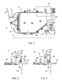
- the combustor 2 shown in Figure 1 is an annular combustion chamber centred on the axis X of the engine.
- the axis X is shown only for purposes of reference in Figure 1 ; in fact it is situated further than shown from the section of the combustion chamber 2 visible in Figure 1 .
- the combustor 2 is situated downstream of the high pressure (HP) compressor (not shown) of the engine. High pressure air issuing from the HP compressor is discharged into a region 4 of the engine which surrounds the annular combustor 2. The forward end 6 of the combustor 2 is open to allow air from the region 4 to enter the interior 8 of the combustor 2.
- a fuel delivery device 8 having a spray nozzle 9 is provided for delivering fuel to the interior of the combustor 2.
- the aft end of the combustor 2 opens at an array of nozzle guide vanes 10 at the entry to the turbine section of the engine (not shown).
- the nozzle guide vanes 10 extend between inner and outer annular vane platforms 12, 14.
- the combustor 2 comprises inner and outer annular walls 16, 18 which terminate respectively at the inner and outer vane platforms 12, 14.
- the outer wall 18 of the combustor 2 terminates short of the outer vane platform 14 to leave a gap 20.
- the outer wall 18 terminates at a flange 22 having a rim 24.
- the outer surface of the rim 24 carries a sealing element 26 in the form of an annular leaf spring.
- the leaf spring 26 is secured at one edge, to the outer surface of the rim 24, so that the edge constitute a retaining portion of the leaf spring 26.
- the leaf spring 26 extends obliquely away from the rim 24 in the forwards direction, and terminates at a sealing lip 28.
- the leaf spring 26 is surrounded on its outside by a closure mechanism comprising an actuator device formed from an array of arcuate actuator elements 30.
- Each actuator element 30 has an operating member 32, and the operating members 32 are controlled by a common control mechanism (not shown) to displace the actuator elements radially inwardly and outwardly in unison.
- Adjacent actuator elements 30 engage one another at an overlapping joint 34, which provides a seal between the actuator elements 30.
- the outer vane platform 14 is provided with a circumferential rib 36 which supports a second annular leaf seal 38.
- the second leaf seal 28 is supported on the rib 36 by a series of pins 40, and is biased into contact with the aft edges of the actuator elements 30.
- the actuator elements 30 are displaced radially inwards, into a closing relationship with the gap 20, in which they contact the sealing lip 28 of the leaf spring 26. This prevents air from flowing between the rim 24 and the actuator elements 30 to the gap 20.
- the second leaf spring 38 provides a further seal between the region 4 and the gap 20. Consequently, no flow can take place through the gap 20 to the interior of the combustor 2 from the outside region 4.
- the actuator elements 30 are displaced radially outwardly from the closing relationship, and so lose contact with the sealing lip 28 of the leaf spring 26.
- the second leaf spring 38 remains in contact with the aft edges of the actuator elements 30, so that flow past the second leaf spring 38 to the gap 20 is prevented.
- flow can take place, as indicated by an arrow F, from the region 4 through the gap 20 to the interior of the combustor 2.
- a proportion of the total output of the HP compressor flows from the region 4 through the open end 6 of the combustor to be mixed with fuel issuing from the spray nozzle 9.
- This mixing occurs in a pre-mixing zone 40 within the combustor, and the air-fuel mixture is initially ignited by means of a spark to create a flame which is subsequently self-sustaining.
- Combustion continues in a reaction zone 42 in which secondary air is admitted through fixed apertures in the walls 16, 18.
- the secondary air mixes with the combustion products in a dilution zone 44 so as to cool the combustion products before they travel past the nozzle guide vanes 10 to the turbine section of the engine.
- the gap 20 is closed by the actuator elements 30, which assume the position shown in Figure 2 .
- the pressure drop from the region 4 to the interior of the combustor 2 will act on the leaf spring 26 to urge the sealing lip 28 into contact with the actuator elements 30.
- maximum flow takes place through the open forward end 6 of the combustor 2, to achieve the desired air/fuel ratio with the increased fuel delivery required for high power operation.
- the actuator elements 30 are displaced radially outwardly, as shown in Figure 3 , to admit a proportion of the air from the region 4 to the interior of the combustor 2 immediately upstream of the nozzle guide vanes 10. This reduces the proportion of the air from the region 4 flowing through the open end 6 of the combustor 2, so as to match the reduced fuel flow rate.
- the distribution of pressure drop for the air entering the combustor through the gap 20 can be arranged so that the flow velocity can be optimised to the performance requirements of the nozzle guide vanes 10.
- the reduced fuel injector air flow (i.e. air flow through the open end 6 of the combustor 2) not only increases the flame temperature, but also increases the combustion residence time, so promoting combustion efficiency.
- the ability to modulate the fuel injector air flow by opening and closing the gap 20 to the flow F means that combustion efficiency, and low emissions, can be achieved both under high power operation of the engine and during cruise at relatively low power. Consequently, both low NOx at high power, lean burn operation and low CO emissions under cruise conditions can be achieved.
- the ability to vary the mass flow rate of air through the open end 6 of the combustor by opening and closing the gap 20 enables a turndown ratio (the ratio between maximum and minimum fuel flow rates) of 6 to 8 to be achieved while maintaining desired emission and SFC levels.
- a further advantage of the ability to admit air to the combustor through the gap 20 is improved relighting of the engine following flame out at altitude.
- An engine configured for lean burn can be difficult to relight at altitude, owing to the high combustor loading (i.e. the high flow rate of air through the open end 6 of the combustor 2).
- the air flow velocity at the spray nozzle 9 is reduced, which can increase the altitude at which relighting can occur by, for example, approximately 600 metres.
- Figure 5 shows an alternative embodiment in which the leaf springs 26 and 38 are replaced by a single leaf spring 26 which extends across the gap 20.
- the leaf spring 26 is mounted at a retaining portion 46 to the rib 36 and extends across the gap 20 to a sealing lip 28.
- the sealing lip 28 is spaced from the upper end of the flange 22, allowing the flow F to pass through the gap 20.
- An actuator device 48 comprising a circumferential array of pins (only one shown in Figure 5 ), can be displaced radially inwardly so as to engage the leaf spring 28 until the sealing lip 26 contacts the outer end of the flange 22, so closing the gap 20.
- the motion of the actuator device comprising the actuator elements 30 and the pins 48 may be modulated in accordance with the operating condition of the engine, so that the NOx/CO trade at cruise conditions can be optimised across a range of cruise conditions.
Landscapes
- Engineering & Computer Science (AREA)
- Mechanical Engineering (AREA)
- General Engineering & Computer Science (AREA)
- Chemical & Material Sciences (AREA)
- Combustion & Propulsion (AREA)
- Turbine Rotor Nozzle Sealing (AREA)
- Control Of Turbines (AREA)
Applications Claiming Priority (1)
| Application Number | Priority Date | Filing Date | Title |
|---|---|---|---|
| GBGB1200237.4A GB201200237D0 (en) | 2012-01-09 | 2012-01-09 | A combustor for a gas turbine engine |
Publications (3)
| Publication Number | Publication Date |
|---|---|
| EP2613084A2 true EP2613084A2 (de) | 2013-07-10 |
| EP2613084A3 EP2613084A3 (de) | 2018-01-10 |
| EP2613084B1 EP2613084B1 (de) | 2019-05-29 |
Family
ID=45788613
Family Applications (1)
| Application Number | Title | Priority Date | Filing Date |
|---|---|---|---|
| EP12197520.5A Active EP2613084B1 (de) | 2012-01-09 | 2012-12-17 | Brennkammer für einen Gasturbinenmotor |
Country Status (3)
| Country | Link |
|---|---|
| US (1) | US8726626B2 (de) |
| EP (1) | EP2613084B1 (de) |
| GB (1) | GB201200237D0 (de) |
Cited By (1)
| Publication number | Priority date | Publication date | Assignee | Title |
|---|---|---|---|---|
| WO2020249915A1 (fr) * | 2019-06-13 | 2020-12-17 | Safran | Ensemble pour une turbine a gaz |
Families Citing this family (9)
| Publication number | Priority date | Publication date | Assignee | Title |
|---|---|---|---|---|
| DE102012204162A1 (de) * | 2012-03-16 | 2013-09-19 | Siemens Aktiengesellschaft | Ringbrennkammer-Bypass |
| EP3299583B1 (de) * | 2013-09-10 | 2019-10-30 | United Technologies Corporation | Hochdruckturbinenleitschaufelträger mit mitteln zur verdrehsicherung und druckstosskompensation |
| GB2545459B (en) | 2015-12-17 | 2020-05-06 | Rolls Royce Plc | A combustion chamber |
| US10837299B2 (en) | 2017-03-07 | 2020-11-17 | General Electric Company | System and method for transition piece seal |
| US12078100B2 (en) | 2021-12-03 | 2024-09-03 | General Electric Company | Combustor size rating for a gas turbine engine using hydrogen fuel |
| US12460573B2 (en) | 2021-12-03 | 2025-11-04 | General Electric Company | Combustor size rating for a gas turbine engine using hydrogen fuel |
| US12416408B2 (en) | 2021-12-03 | 2025-09-16 | General Electric Company | Combustor size rating for a gas turbine engine using hydrogen fuel |
| US12405007B2 (en) | 2021-12-03 | 2025-09-02 | General Electric Company | Combustor size rating for a gas turbine engine using hydrogen fuel |
| US12454909B2 (en) | 2021-12-03 | 2025-10-28 | General Electric Company | Combustor size rating for a gas turbine engine using hydrogen fuel |
Family Cites Families (15)
| Publication number | Priority date | Publication date | Assignee | Title |
|---|---|---|---|---|
| US3869246A (en) * | 1973-12-26 | 1975-03-04 | Gen Motors Corp | Variable configuration combustion apparatus |
| US3958413A (en) * | 1974-09-03 | 1976-05-25 | General Motors Corporation | Combustion method and apparatus |
| US4497170A (en) * | 1982-07-22 | 1985-02-05 | The Garrett Corporation | Actuation system for a variable geometry combustor |
| JPS5956022A (ja) * | 1982-09-20 | 1984-03-31 | Toshiba Corp | ガスタ−ビン燃焼器 |
| US4807433A (en) * | 1983-05-05 | 1989-02-28 | General Electric Company | Turbine cooling air modulation |
| EP0312620B1 (de) * | 1987-10-19 | 1991-06-12 | Hitachi, Ltd. | Einrichtung zur Regulierung des Verbrennungsluftdurchsatzes in Gasturbinenbrennkammern |
| JP2516822Y2 (ja) * | 1988-08-04 | 1996-11-13 | 川崎重工業株式会社 | ガスタービン用燃焼器 |
| GB9305012D0 (en) * | 1993-03-11 | 1993-04-28 | Rolls Royce Plc | Sealing structures for gas turbine engines |
| DE69421896T2 (de) * | 1993-12-22 | 2000-05-31 | Siemens Westinghouse Power Corp., Orlando | Umleitungsventil für die Brennkammer einer Gasturbine |
| JP2000257861A (ja) | 1999-03-11 | 2000-09-22 | Senshin Zairyo Riyo Gas Generator Kenkyusho:Kk | ガスタービン用燃焼装置 |
| US6547257B2 (en) * | 2001-05-04 | 2003-04-15 | General Electric Company | Combination transition piece floating cloth seal and stage 1 turbine nozzle flexible sealing element |
| JP2003329244A (ja) * | 2002-05-14 | 2003-11-19 | Mitsubishi Heavy Ind Ltd | ガスタービン用燃焼器及びその燃焼制御方法 |
| GB0319329D0 (en) | 2003-08-16 | 2003-09-17 | Rolls Royce Plc | Variable geometry combustor |
| GB0419436D0 (en) * | 2004-09-02 | 2004-10-06 | Rolls Royce Plc | An arrangement for controlling flow of fluid to a component of a gas turbine engine |
| RU2010101978A (ru) * | 2010-01-15 | 2011-07-20 | Дженерал Электрик Компани (US) | Соединительный узел для газовой турбины |
-
2012
- 2012-01-09 GB GBGB1200237.4A patent/GB201200237D0/en not_active Ceased
- 2012-12-17 US US13/716,953 patent/US8726626B2/en active Active
- 2012-12-17 EP EP12197520.5A patent/EP2613084B1/de active Active
Cited By (4)
| Publication number | Priority date | Publication date | Assignee | Title |
|---|---|---|---|---|
| WO2020249915A1 (fr) * | 2019-06-13 | 2020-12-17 | Safran | Ensemble pour une turbine a gaz |
| FR3097299A1 (fr) * | 2019-06-13 | 2020-12-18 | Safran | Ensemble pour une turbine a gaz |
| CN114174641A (zh) * | 2019-06-13 | 2022-03-11 | 赛峰公司 | 用于燃气涡轮机的组合件 |
| CN114174641B (zh) * | 2019-06-13 | 2024-06-07 | 赛峰公司 | 用于燃气涡轮机的组合件 |
Also Published As
| Publication number | Publication date |
|---|---|
| EP2613084A3 (de) | 2018-01-10 |
| EP2613084B1 (de) | 2019-05-29 |
| US20130174557A1 (en) | 2013-07-11 |
| US8726626B2 (en) | 2014-05-20 |
| GB201200237D0 (en) | 2012-02-22 |
Similar Documents
| Publication | Publication Date | Title |
|---|---|---|
| US8726626B2 (en) | Combustor for a gas turbine engine | |
| US7762073B2 (en) | Pilot mixer for mixer assembly of a gas turbine engine combustor having a primary fuel injector and a plurality of secondary fuel injection ports | |
| US8001761B2 (en) | Method and apparatus for actively controlling fuel flow to a mixer assembly of a gas turbine engine combustor | |
| EP1499800B1 (de) | Kraftstoffvormischmodul für turbomotorbrennkammer | |
| EP2551596B1 (de) | Brennkammer, Brenner und Gasturbine | |
| EP2831505B1 (de) | Verbrenneranordnung einer turbomaschine | |
| US11747018B2 (en) | Combustor with dilution openings | |
| US20070028620A1 (en) | Free floating mixer assembly for combustor of a gas turbine engine | |
| US12031486B2 (en) | Combustor with lean openings | |
| US20180356093A1 (en) | Methods of operating a rotating detonation combustor at approximately constant detonation cell size | |
| CN116518417B (zh) | 燃气涡轮发动机和用于燃气涡轮发动机的燃烧区段 | |
| EP2481985B1 (de) | Kraftstoffeinspritzanordnung | |
| US20050034444A1 (en) | Fuel injector | |
| KR20150065819A (ko) | 멀티 스테이지 연소기용 유동 분할기 기구 | |
| US20140352312A1 (en) | Injector for introducing a fuel-air mixture into a combustion chamber | |
| GB2451144A (en) | Method and apparatus for actively controlling fuel flow to a mixer assembly of a gas turbine engine combustor | |
| US11209163B2 (en) | Gas turbine combustor, manufacturing method for gas turbine and gas turbine combustor | |
| CA2595061C (en) | Method and apparatus for actively controlling fuel flow to a mixer assembly of a gas turbine engine combustor | |
| GB2451517A (en) | Pilot mixer for mixer assembly of a gas turbine engine combustor having a primary fuel injector and a plurality of secondary fuel injection ports | |
| US11885498B2 (en) | Turbine engine with fuel system including a catalytic reformer | |
| EP4678892A1 (de) | Gasturbinentriebwerk und brennstoffdüsenanordnung dafür | |
| EP4411232A1 (de) | Kraftstoffverteiler mit hoher scherung | |
| EP4411229B1 (de) | Brennkammer für gasturbinenmotor mit zentralen brennstoffeinspritzöffnungen | |
| JP4995657B2 (ja) | ガスタービンエンジン燃焼器のミキサ組立体への燃料流量を能動的に制御するための装置 | |
| US20200103113A1 (en) | Combustion chamber assembly for an engine having heat shields and/or burner seals of at least two different types |
Legal Events
| Date | Code | Title | Description |
|---|---|---|---|
| PUAI | Public reference made under article 153(3) epc to a published international application that has entered the european phase |
Free format text: ORIGINAL CODE: 0009012 |
|
| AK | Designated contracting states |
Kind code of ref document: A2 Designated state(s): AL AT BE BG CH CY CZ DE DK EE ES FI FR GB GR HR HU IE IS IT LI LT LU LV MC MK MT NL NO PL PT RO RS SE SI SK SM TR |
|
| AX | Request for extension of the european patent |
Extension state: BA ME |
|
| RAP1 | Party data changed (applicant data changed or rights of an application transferred) |
Owner name: ROLLS-ROYCE PLC |
|
| PUAL | Search report despatched |
Free format text: ORIGINAL CODE: 0009013 |
|
| AK | Designated contracting states |
Kind code of ref document: A3 Designated state(s): AL AT BE BG CH CY CZ DE DK EE ES FI FR GB GR HR HU IE IS IT LI LT LU LV MC MK MT NL NO PL PT RO RS SE SI SK SM TR |
|
| AX | Request for extension of the european patent |
Extension state: BA ME |
|
| RIC1 | Information provided on ipc code assigned before grant |
Ipc: F23R 3/04 20060101AFI20171205BHEP Ipc: F23R 3/26 20060101ALI20171205BHEP |
|
| STAA | Information on the status of an ep patent application or granted ep patent |
Free format text: STATUS: REQUEST FOR EXAMINATION WAS MADE |
|
| 17P | Request for examination filed |
Effective date: 20180710 |
|
| RBV | Designated contracting states (corrected) |
Designated state(s): AL AT BE BG CH CY CZ DE DK EE ES FI FR GB GR HR HU IE IS IT LI LT LU LV MC MK MT NL NO PL PT RO RS SE SI SK SM TR |
|
| GRAP | Despatch of communication of intention to grant a patent |
Free format text: ORIGINAL CODE: EPIDOSNIGR1 |
|
| STAA | Information on the status of an ep patent application or granted ep patent |
Free format text: STATUS: GRANT OF PATENT IS INTENDED |
|
| INTG | Intention to grant announced |
Effective date: 20190213 |
|
| GRAS | Grant fee paid |
Free format text: ORIGINAL CODE: EPIDOSNIGR3 |
|
| GRAA | (expected) grant |
Free format text: ORIGINAL CODE: 0009210 |
|
| STAA | Information on the status of an ep patent application or granted ep patent |
Free format text: STATUS: THE PATENT HAS BEEN GRANTED |
|
| AK | Designated contracting states |
Kind code of ref document: B1 Designated state(s): AL AT BE BG CH CY CZ DE DK EE ES FI FR GB GR HR HU IE IS IT LI LT LU LV MC MK MT NL NO PL PT RO RS SE SI SK SM TR |
|
| REG | Reference to a national code |
Ref country code: GB Ref legal event code: FG4D |
|
| REG | Reference to a national code |
Ref country code: CH Ref legal event code: EP |
|
| REG | Reference to a national code |
Ref country code: AT Ref legal event code: REF Ref document number: 1138482 Country of ref document: AT Kind code of ref document: T Effective date: 20190615 |
|
| REG | Reference to a national code |
Ref country code: DE Ref legal event code: R096 Ref document number: 602012060553 Country of ref document: DE |
|
| REG | Reference to a national code |
Ref country code: IE Ref legal event code: FG4D |
|
| REG | Reference to a national code |
Ref country code: NL Ref legal event code: MP Effective date: 20190529 |
|
| REG | Reference to a national code |
Ref country code: LT Ref legal event code: MG4D |
|
| PG25 | Lapsed in a contracting state [announced via postgrant information from national office to epo] |
Ref country code: SE Free format text: LAPSE BECAUSE OF FAILURE TO SUBMIT A TRANSLATION OF THE DESCRIPTION OR TO PAY THE FEE WITHIN THE PRESCRIBED TIME-LIMIT Effective date: 20190529 Ref country code: HR Free format text: LAPSE BECAUSE OF FAILURE TO SUBMIT A TRANSLATION OF THE DESCRIPTION OR TO PAY THE FEE WITHIN THE PRESCRIBED TIME-LIMIT Effective date: 20190529 Ref country code: ES Free format text: LAPSE BECAUSE OF FAILURE TO SUBMIT A TRANSLATION OF THE DESCRIPTION OR TO PAY THE FEE WITHIN THE PRESCRIBED TIME-LIMIT Effective date: 20190529 Ref country code: LT Free format text: LAPSE BECAUSE OF FAILURE TO SUBMIT A TRANSLATION OF THE DESCRIPTION OR TO PAY THE FEE WITHIN THE PRESCRIBED TIME-LIMIT Effective date: 20190529 Ref country code: PT Free format text: LAPSE BECAUSE OF FAILURE TO SUBMIT A TRANSLATION OF THE DESCRIPTION OR TO PAY THE FEE WITHIN THE PRESCRIBED TIME-LIMIT Effective date: 20190930 Ref country code: NO Free format text: LAPSE BECAUSE OF FAILURE TO SUBMIT A TRANSLATION OF THE DESCRIPTION OR TO PAY THE FEE WITHIN THE PRESCRIBED TIME-LIMIT Effective date: 20190829 Ref country code: AL Free format text: LAPSE BECAUSE OF FAILURE TO SUBMIT A TRANSLATION OF THE DESCRIPTION OR TO PAY THE FEE WITHIN THE PRESCRIBED TIME-LIMIT Effective date: 20190529 Ref country code: FI Free format text: LAPSE BECAUSE OF FAILURE TO SUBMIT A TRANSLATION OF THE DESCRIPTION OR TO PAY THE FEE WITHIN THE PRESCRIBED TIME-LIMIT Effective date: 20190529 |
|
| PG25 | Lapsed in a contracting state [announced via postgrant information from national office to epo] |
Ref country code: BG Free format text: LAPSE BECAUSE OF FAILURE TO SUBMIT A TRANSLATION OF THE DESCRIPTION OR TO PAY THE FEE WITHIN THE PRESCRIBED TIME-LIMIT Effective date: 20190829 Ref country code: RS Free format text: LAPSE BECAUSE OF FAILURE TO SUBMIT A TRANSLATION OF THE DESCRIPTION OR TO PAY THE FEE WITHIN THE PRESCRIBED TIME-LIMIT Effective date: 20190529 Ref country code: LV Free format text: LAPSE BECAUSE OF FAILURE TO SUBMIT A TRANSLATION OF THE DESCRIPTION OR TO PAY THE FEE WITHIN THE PRESCRIBED TIME-LIMIT Effective date: 20190529 Ref country code: GR Free format text: LAPSE BECAUSE OF FAILURE TO SUBMIT A TRANSLATION OF THE DESCRIPTION OR TO PAY THE FEE WITHIN THE PRESCRIBED TIME-LIMIT Effective date: 20190830 |
|
| REG | Reference to a national code |
Ref country code: AT Ref legal event code: MK05 Ref document number: 1138482 Country of ref document: AT Kind code of ref document: T Effective date: 20190529 |
|
| PG25 | Lapsed in a contracting state [announced via postgrant information from national office to epo] |
Ref country code: DK Free format text: LAPSE BECAUSE OF FAILURE TO SUBMIT A TRANSLATION OF THE DESCRIPTION OR TO PAY THE FEE WITHIN THE PRESCRIBED TIME-LIMIT Effective date: 20190529 Ref country code: NL Free format text: LAPSE BECAUSE OF FAILURE TO SUBMIT A TRANSLATION OF THE DESCRIPTION OR TO PAY THE FEE WITHIN THE PRESCRIBED TIME-LIMIT Effective date: 20190529 Ref country code: SK Free format text: LAPSE BECAUSE OF FAILURE TO SUBMIT A TRANSLATION OF THE DESCRIPTION OR TO PAY THE FEE WITHIN THE PRESCRIBED TIME-LIMIT Effective date: 20190529 Ref country code: CZ Free format text: LAPSE BECAUSE OF FAILURE TO SUBMIT A TRANSLATION OF THE DESCRIPTION OR TO PAY THE FEE WITHIN THE PRESCRIBED TIME-LIMIT Effective date: 20190529 Ref country code: RO Free format text: LAPSE BECAUSE OF FAILURE TO SUBMIT A TRANSLATION OF THE DESCRIPTION OR TO PAY THE FEE WITHIN THE PRESCRIBED TIME-LIMIT Effective date: 20190529 Ref country code: EE Free format text: LAPSE BECAUSE OF FAILURE TO SUBMIT A TRANSLATION OF THE DESCRIPTION OR TO PAY THE FEE WITHIN THE PRESCRIBED TIME-LIMIT Effective date: 20190529 Ref country code: AT Free format text: LAPSE BECAUSE OF FAILURE TO SUBMIT A TRANSLATION OF THE DESCRIPTION OR TO PAY THE FEE WITHIN THE PRESCRIBED TIME-LIMIT Effective date: 20190529 |
|
| RAP2 | Party data changed (patent owner data changed or rights of a patent transferred) |
Owner name: ROLLS-ROYCE PLC |
|
| PG25 | Lapsed in a contracting state [announced via postgrant information from national office to epo] |
Ref country code: IT Free format text: LAPSE BECAUSE OF FAILURE TO SUBMIT A TRANSLATION OF THE DESCRIPTION OR TO PAY THE FEE WITHIN THE PRESCRIBED TIME-LIMIT Effective date: 20190529 Ref country code: SM Free format text: LAPSE BECAUSE OF FAILURE TO SUBMIT A TRANSLATION OF THE DESCRIPTION OR TO PAY THE FEE WITHIN THE PRESCRIBED TIME-LIMIT Effective date: 20190529 |
|
| REG | Reference to a national code |
Ref country code: DE Ref legal event code: R097 Ref document number: 602012060553 Country of ref document: DE |
|
| PG25 | Lapsed in a contracting state [announced via postgrant information from national office to epo] |
Ref country code: TR Free format text: LAPSE BECAUSE OF FAILURE TO SUBMIT A TRANSLATION OF THE DESCRIPTION OR TO PAY THE FEE WITHIN THE PRESCRIBED TIME-LIMIT Effective date: 20190529 |
|
| PLBE | No opposition filed within time limit |
Free format text: ORIGINAL CODE: 0009261 |
|
| STAA | Information on the status of an ep patent application or granted ep patent |
Free format text: STATUS: NO OPPOSITION FILED WITHIN TIME LIMIT |
|
| PG25 | Lapsed in a contracting state [announced via postgrant information from national office to epo] |
Ref country code: PL Free format text: LAPSE BECAUSE OF FAILURE TO SUBMIT A TRANSLATION OF THE DESCRIPTION OR TO PAY THE FEE WITHIN THE PRESCRIBED TIME-LIMIT Effective date: 20190529 |
|
| 26N | No opposition filed |
Effective date: 20200303 |
|
| PG25 | Lapsed in a contracting state [announced via postgrant information from national office to epo] |
Ref country code: SI Free format text: LAPSE BECAUSE OF FAILURE TO SUBMIT A TRANSLATION OF THE DESCRIPTION OR TO PAY THE FEE WITHIN THE PRESCRIBED TIME-LIMIT Effective date: 20190529 |
|
| REG | Reference to a national code |
Ref country code: CH Ref legal event code: PL |
|
| REG | Reference to a national code |
Ref country code: BE Ref legal event code: MM Effective date: 20191231 |
|
| PG25 | Lapsed in a contracting state [announced via postgrant information from national office to epo] |
Ref country code: MC Free format text: LAPSE BECAUSE OF FAILURE TO SUBMIT A TRANSLATION OF THE DESCRIPTION OR TO PAY THE FEE WITHIN THE PRESCRIBED TIME-LIMIT Effective date: 20190529 |
|
| PG25 | Lapsed in a contracting state [announced via postgrant information from national office to epo] |
Ref country code: LU Free format text: LAPSE BECAUSE OF NON-PAYMENT OF DUE FEES Effective date: 20191217 Ref country code: IE Free format text: LAPSE BECAUSE OF NON-PAYMENT OF DUE FEES Effective date: 20191217 |
|
| PG25 | Lapsed in a contracting state [announced via postgrant information from national office to epo] |
Ref country code: LI Free format text: LAPSE BECAUSE OF NON-PAYMENT OF DUE FEES Effective date: 20191231 Ref country code: CH Free format text: LAPSE BECAUSE OF NON-PAYMENT OF DUE FEES Effective date: 20191231 Ref country code: BE Free format text: LAPSE BECAUSE OF NON-PAYMENT OF DUE FEES Effective date: 20191231 |
|
| PG25 | Lapsed in a contracting state [announced via postgrant information from national office to epo] |
Ref country code: CY Free format text: LAPSE BECAUSE OF FAILURE TO SUBMIT A TRANSLATION OF THE DESCRIPTION OR TO PAY THE FEE WITHIN THE PRESCRIBED TIME-LIMIT Effective date: 20190529 |
|
| PG25 | Lapsed in a contracting state [announced via postgrant information from national office to epo] |
Ref country code: IS Free format text: LAPSE BECAUSE OF FAILURE TO SUBMIT A TRANSLATION OF THE DESCRIPTION OR TO PAY THE FEE WITHIN THE PRESCRIBED TIME-LIMIT Effective date: 20190929 |
|
| PG25 | Lapsed in a contracting state [announced via postgrant information from national office to epo] |
Ref country code: MT Free format text: LAPSE BECAUSE OF FAILURE TO SUBMIT A TRANSLATION OF THE DESCRIPTION OR TO PAY THE FEE WITHIN THE PRESCRIBED TIME-LIMIT Effective date: 20190529 Ref country code: HU Free format text: LAPSE BECAUSE OF FAILURE TO SUBMIT A TRANSLATION OF THE DESCRIPTION OR TO PAY THE FEE WITHIN THE PRESCRIBED TIME-LIMIT; INVALID AB INITIO Effective date: 20121217 |
|
| PG25 | Lapsed in a contracting state [announced via postgrant information from national office to epo] |
Ref country code: MK Free format text: LAPSE BECAUSE OF FAILURE TO SUBMIT A TRANSLATION OF THE DESCRIPTION OR TO PAY THE FEE WITHIN THE PRESCRIBED TIME-LIMIT Effective date: 20190529 |
|
| P01 | Opt-out of the competence of the unified patent court (upc) registered |
Effective date: 20230528 |
|
| PGFP | Annual fee paid to national office [announced via postgrant information from national office to epo] |
Ref country code: GB Payment date: 20241217 Year of fee payment: 13 |
|
| PGFP | Annual fee paid to national office [announced via postgrant information from national office to epo] |
Ref country code: FR Payment date: 20241227 Year of fee payment: 13 |
|
| PGFP | Annual fee paid to national office [announced via postgrant information from national office to epo] |
Ref country code: DE Payment date: 20241227 Year of fee payment: 13 |