EP2613087A2 - Brennkammerbrennstoffdüse und Verfahren zur Versorgung einer Brennkammer mit Brennstoff - Google Patents
Brennkammerbrennstoffdüse und Verfahren zur Versorgung einer Brennkammer mit Brennstoff Download PDFInfo
- Publication number
- EP2613087A2 EP2613087A2 EP12199293.7A EP12199293A EP2613087A2 EP 2613087 A2 EP2613087 A2 EP 2613087A2 EP 12199293 A EP12199293 A EP 12199293A EP 2613087 A2 EP2613087 A2 EP 2613087A2
- Authority
- EP
- European Patent Office
- Prior art keywords
- fuel
- inner shroud
- center body
- combustor
- shroud
- Prior art date
- Legal status (The legal status is an assumption and is not a legal conclusion. Google has not performed a legal analysis and makes no representation as to the accuracy of the status listed.)
- Withdrawn
Links
- 239000000446 fuel Substances 0.000 title claims abstract description 157
- 238000000034 method Methods 0.000 title claims abstract description 15
- 239000012530 fluid Substances 0.000 claims abstract description 61
- 238000011144 upstream manufacturing Methods 0.000 claims abstract description 8
- 239000007788 liquid Substances 0.000 claims description 37
- 238000002485 combustion reaction Methods 0.000 description 17
- 239000007789 gas Substances 0.000 description 15
- 239000000203 mixture Substances 0.000 description 11
- 239000000567 combustion gas Substances 0.000 description 4
- MWUXSHHQAYIFBG-UHFFFAOYSA-N Nitric oxide Chemical compound O=[N] MWUXSHHQAYIFBG-UHFFFAOYSA-N 0.000 description 3
- 239000000654 additive Substances 0.000 description 2
- 230000008901 benefit Effects 0.000 description 2
- 238000012986 modification Methods 0.000 description 2
- 230000004048 modification Effects 0.000 description 2
- 239000007921 spray Substances 0.000 description 2
- 230000007704 transition Effects 0.000 description 2
- XLYOFNOQVPJJNP-UHFFFAOYSA-N water Substances O XLYOFNOQVPJJNP-UHFFFAOYSA-N 0.000 description 2
- 230000004888 barrier function Effects 0.000 description 1
- UHZZMRAGKVHANO-UHFFFAOYSA-M chlormequat chloride Chemical compound [Cl-].C[N+](C)(C)CCCl UHZZMRAGKVHANO-UHFFFAOYSA-M 0.000 description 1
- 238000004891 communication Methods 0.000 description 1
- 238000010790 dilution Methods 0.000 description 1
- 239000012895 dilution Substances 0.000 description 1
- 238000002347 injection Methods 0.000 description 1
- 239000007924 injection Substances 0.000 description 1
- 239000003595 mist Substances 0.000 description 1
- 230000037361 pathway Effects 0.000 description 1
- 238000010248 power generation Methods 0.000 description 1
- 230000008439 repair process Effects 0.000 description 1
- 238000012552 review Methods 0.000 description 1
Images


Classifications
-
- F—MECHANICAL ENGINEERING; LIGHTING; HEATING; WEAPONS; BLASTING
- F23—COMBUSTION APPARATUS; COMBUSTION PROCESSES
- F23R—GENERATING COMBUSTION PRODUCTS OF HIGH PRESSURE OR HIGH VELOCITY, e.g. GAS-TURBINE COMBUSTION CHAMBERS
- F23R3/00—Continuous combustion chambers using liquid or gaseous fuel
- F23R3/02—Continuous combustion chambers using liquid or gaseous fuel characterised by the air-flow or gas-flow configuration
- F23R3/04—Air inlet arrangements
- F23R3/10—Air inlet arrangements for primary air
- F23R3/12—Air inlet arrangements for primary air inducing a vortex
- F23R3/14—Air inlet arrangements for primary air inducing a vortex by using swirl vanes
-
- F—MECHANICAL ENGINEERING; LIGHTING; HEATING; WEAPONS; BLASTING
- F23—COMBUSTION APPARATUS; COMBUSTION PROCESSES
- F23R—GENERATING COMBUSTION PRODUCTS OF HIGH PRESSURE OR HIGH VELOCITY, e.g. GAS-TURBINE COMBUSTION CHAMBERS
- F23R3/00—Continuous combustion chambers using liquid or gaseous fuel
- F23R3/28—Continuous combustion chambers using liquid or gaseous fuel characterised by the fuel supply
- F23R3/286—Continuous combustion chambers using liquid or gaseous fuel characterised by the fuel supply having fuel-air premixing devices
Definitions
- the present invention generally involves a combustor fuel nozzle and a method for supplying fuel to a combustor.
- Gas turbines are widely used in commercial operations for power generation.
- Gas turbine combustors generally operate on a liquid and/or a gaseous fuel mixed with a compressed working fluid such as air.
- the flexibility to run a gas turbine on either fuel provides a great benefit to gas turbine operators.
- the fuel and air may be premixed prior to combustion.
- the premixing may take place in a dual-fuel combustor fuel nozzle, which includes multiple fuel injection ports, an inner flow region and an outer flow region.
- fuel is injected into the inner and/or outer flow regions for premixing with the working fluid.
- dual-fuel nozzles exist which allow premixing of a liquid and/or gaseous fuel with a working fluid prior to combustion.
- an improved fuel nozzle and method for supplying fuel to a combustor that improves the uniformity of the fuel mixture would be useful.
- One aspect of the present invention is a combustor fuel nozzle including a center body and an inner shroud that circumferentially surrounds at least a portion of the center body, wherein the inner shroud has a downstream surface.
- the first plurality of fuel ports is upstream from the downstream surface of the inner shroud.
- the present invention also resides in includes a method for supplying fuel to a combustor fuel nozzle that includes flowing a working fluid through an inner annular passage between a center body and an inner shroud and injecting a first fuel from the center body against the inner shroud.
- the method further includes flowing at least a portion of the working fluid through an outer annular passage that circumferentially surrounds at least a portion of the inner shroud.
- Various embodiments of the present invention include a combustor fuel nozzle and method for providing fuel to a combustor.
- the fuel nozzle generally includes a center body, an inner shroud with a downstream surface, an inner annular passage and an outer annular passage.
- a working fluid may flow through the center body, the inner annular passage and/or the outer annular passage.
- a first plurality of fuel ports, positioned upstream from the downstream surface of the inner shroud, extend generally radially outward through the center body. In this manner, as the working fluid passes through the inner annular passage and a liquid fuel is injected through the first plurality of fuel ports, a portion of the fuel may vaporize and mix with the working fluid. The remainder of the liquid fuel will pre-film on the inner shroud and shear off the downstream surface, thus providing a fine spray of the remaining liquid fuel for further mixing with the working fluid for combustion.
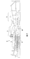
- Fig. 1 shows a typical gas turbine 10 within the scope of the present invention.
- the gas turbine 10 includes a compressor 12 at the front, one or more combustors 14 around the middle, and a turbine 16 at the rear.
- the compressor 12 and the turbine 16 typically share a common rotor 18.
- the compressor 12 imparts kinetic energy to the working fluid (air) to bring it to a highly energized state.
- the compressed working fluid exits the compressor 12 and flows to each combustor 14.
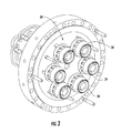
- Fig. 3 provides a perspective view of the end cover assembly 30 shown in Fig. 2 .
- Each fuel nozzle 34 mixes fuel with the compressed working fluid.
- the mixture of fuel and working fluid ignites in the combustion chamber 40, as shown in Fig. 2 , to generate combustion gases having a high temperature, pressure, and velocity.
- the combustion gases flow through the transition piece 32 to the turbine 16 where they expand to produce work.
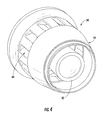
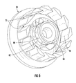
- Fig. 4 provides a perspective view of a fuel nozzle 34 according to one embodiment of the present invention
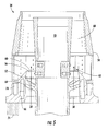
- Fig. 5 provides a cross-section view of the fuel nozzle 34 shown in Fig. 4
- the fuel nozzle 34 generally includes a center body 50, an inner shroud 52 as shown in Fig. 5 , and an outer shroud 54.
- the center body 50 and inner shroud 52 define an inner annular passage 56 between the center body 50 and the inner shroud 52, and the inner annular passage provides an axial flow region 58.
- the inner shroud 52 and outer shroud 54 define an outer annular passage 60 that circumferentially surrounds at least a portion of the inner shroud 52 and provides a radial flow region 62.
- the center body 50 may provide fluid communication through the fuel nozzle 34 and into the combustion chamber 40.
- the center body 50 may be configured to flow the working fluid, a liquid and/or a gaseous fuel.
- the nozzle 34 may include a plurality of vanes 64 that extend radially between the center body 50 and the inner shroud 52 to impart axial swirl to the working fluid as it passes across the vanes 64 and through the axial flow region 58.
- the center body 50 may be breech loaded through the end cover assembly 30 and/or through the inner shroud 52 and the outer shroud 52, thus allowing for removal and/or replacement of the center body 50 from the fuel nozzle 34.
- the center body 50 may diverge radially outward and/or converge radially inward, and the center body 50 may be any shape, for example, it does not have to be circular, cylindrical or symmetric.
- the inner shroud 52 circumferentially surrounds at least a portion of the center body 50 and forms an inner annular passage 56 between the center body and the inner shroud 52.
- the inner annular passage 56 provides the axial flow region 58 between the center body 50 and the inner shroud 52.
- the inner shroud 52 directs the working fluid through the axial flow region 58.
- the inner shroud 52 may include one or more fluid circuits 66, and the one or fluid circuits 66 may be configured to flow a liquid or gaseous fuel.
- the inner shroud 52 has a downstream surface 68. In particular embodiments, the downstream surface 68 may terminate at a point.
- a sharp or knife-edge may be formed along the downstream surface 68 at the termination point.
- the inner shroud 52 may converge toward the center body 50 to narrow the width of the inner annular passage 56. In this manner, as the working fluid passes through the axial flow region 58, the converging inner shroud 52 may accelerate the working fluid and direct the working fluid in an axial direction along the center body 50. Similarly, the inner shroud 52 may diverge from the outer shroud 54.
- the diverging inner shroud 52 may provide a barrier to segregate the radial flow region 62 from the axial flow region 58 and may direct the working fluid axially downstream from the inner shroud 52 downstream surface 68.
- the outer shroud 54 circumferentially surrounds at least a portion of the inner shroud 52 and/or center body 50 to confine the working fluid and/or fuel flowing through the fuel nozzle 34.
- the outer shroud 54 may include one or more fluid circuits 70, and the one or more fluid circuits 70 may be configured to flow a liquid or gaseous fuel.
- the outer shroud 54 may be a separate structure or it may be integrally connected to the inner shroud 52.
- the outer shroud 54 and/or the inner shroud 52 may be rigidly connected to the combustor, for example, by a strut 74 or by any other means for supporting a structure.
- the angled passages 72 may impart radial swirl to the working fluid and/or fuel flowing through the fuel nozzle 34 in the same direction or in opposition directions from the swirl provided by the center body 50 radially extending vanes 64 within the axial flow region 58, depending on the particular embodiment.
- the outer shroud 54 may converge radially inward downstream of the inner shroud downstream surface 68. In this manner, the pre-mixed working fluid and fuel may become compressed and/or accelerate as it leaves the fuel nozzle 34 before expanding into the combustion chamber 34 for burning, thus reducing the risk of flame holding or flashback at the exit plane of the fuel nozzle 34.
- Fig. 7 provides an enlarged cross-section of a portion of the fuel nozzle 34 shown in Fig. 4 .
- the fuel nozzle 34 may include a plurality of fuel ports in one or more of the center body 50, inner shroud 52, and outer shroud 54.
- Each fuel port may be angled radially, axially, and/or azimuthally to project and/or impart swirl to the fuel flowing through the fuel ports and into the fuel nozzle 34.
- Each of the fuel ports may be configured to flow gaseous and/or liquid fuels. In the particular embodiment, as shown in Fig.
- a first plurality of fuel ports 82 may extend substantially radially outward through the center body 50 and may operate independently or in conjunction with one or more of the plurality of fuel ports.
- the first plurality of fuel ports 82 is upstream from the downstream surface 68 of the inner shroud 52 and may be configured to provide a gaseous or a liquid fuel. In this manner, when the first plurality of fuel ports 82 injects a liquid fuel radially outward from the center body 50 and into the inner annular passage 56, at least a portion of the liquid fuel will be vaporized and mixed with the working fluid as it passes through the axial flow region 58. However, the remaining portion of liquid fuel will generally strike the inner shroud 52.
- the working fluid in the axial flow region 58 will cause the remaining liquid fuel to pre-film on the inner shroud 52 as it transfers the pre-filmed liquid fuel across the converging inner shroud downstream surface 68.
- the pre-filmed fluid may be sheared into droplets and distributed into the counter rotating air streams created within the axial flow region 58 and the radial flow region 62.
- a very fine and consistent liquid fuel spray is provided for improved fuel and working fluid mixing prior to combustion, thus reducing the amount of water or other additives necessary to control combustion emissions and further improving the overall efficiency of the gas turbine while running on a liquid fuel.
- the inner shroud 52 will at least partially segregate the liquid fuel and working fluid mixture in the axial flow region 58 from the radial flow region 62, thus allowing greater control over the inner and outer fuel mix split during operation of the gas turbine.
- the inner shroud downstream surface 68 may accelerate and direct the working fluid and gaseous fuel mixture generally axially along the center body 50, thus at least partially segregating the axial flow region 58 from the radial flow region 62, thereby providing greater control over inner and outer fuel mixing split during operation of the gas turbine.
- a fourth plurality of fuel ports 88 downstream from the downstream surface 68 of the inner shroud 52, may extend substantially radially outward through the center body 50 and may be configured to flow a liquid or gaseous fuel.
- a liquid fuel may be injected from the fourth plurality of fuel ports 88 and into the radial flow region 62 of the fuel nozzle 34.
- the remaining portion of liquid fuel may be air blasted by the intense shear generated by the counter swirling working fluid from both the axial and radial flow regions 58 & 62 respectfully.
- the liquid fuel may be further vaporized, thus resulting in a fine and consistent mist of liquid fuel.
- the vaporized liquid fuel will more easily pre-mix with the working fluid prior to combustion.
- the method may further include pre-filming the liquid fuel along the inner shroud 52, wherein the inner shroud converges radially inward towards the center body 50 and the downstream surface 68 terminates at a point.
- the downstream surface 68 may form a knife-edge.
- the method may further include swirling the working fluid flowing through the inner annular passage 56 in a first direction and swirling the working fluid flowing through the outer annular passage 60 in a second direction, wherein the first direction is opposite from the second direction.
Landscapes
- Engineering & Computer Science (AREA)
- Chemical & Material Sciences (AREA)
- Combustion & Propulsion (AREA)
- Mechanical Engineering (AREA)
- General Engineering & Computer Science (AREA)
- Spray-Type Burners (AREA)
- Fuel-Injection Apparatus (AREA)
Applications Claiming Priority (1)
| Application Number | Priority Date | Filing Date | Title |
|---|---|---|---|
| US13/344,033 US9182123B2 (en) | 2012-01-05 | 2012-01-05 | Combustor fuel nozzle and method for supplying fuel to a combustor |
Publications (1)
| Publication Number | Publication Date |
|---|---|
| EP2613087A2 true EP2613087A2 (de) | 2013-07-10 |
Family
ID=47678526
Family Applications (1)
| Application Number | Title | Priority Date | Filing Date |
|---|---|---|---|
| EP12199293.7A Withdrawn EP2613087A2 (de) | 2012-01-05 | 2012-12-21 | Brennkammerbrennstoffdüse und Verfahren zur Versorgung einer Brennkammer mit Brennstoff |
Country Status (5)
| Country | Link |
|---|---|
| US (1) | US9182123B2 (de) |
| EP (1) | EP2613087A2 (de) |
| JP (1) | JP2013140004A (de) |
| CN (1) | CN103196156A (de) |
| RU (1) | RU2012158299A (de) |
Families Citing this family (16)
| Publication number | Priority date | Publication date | Assignee | Title |
|---|---|---|---|---|
| US9188085B2 (en) * | 2012-10-31 | 2015-11-17 | Electro-Motive Diesel, Inc. | Fuel system having multiple gaseous fuel injectors |
| KR102129052B1 (ko) * | 2013-11-12 | 2020-07-02 | 한화에어로스페이스 주식회사 | 스월러 어셈블리 |
| US10184665B2 (en) | 2015-06-10 | 2019-01-22 | General Electric Company | Prefilming air blast (PAB) pilot having annular splitter surrounding a pilot fuel injector |
| US20170268785A1 (en) * | 2016-03-15 | 2017-09-21 | General Electric Company | Staged fuel and air injectors in combustion systems of gas turbines |
| ITUA20163988A1 (it) * | 2016-05-31 | 2017-12-01 | Nuovo Pignone Tecnologie Srl | Ugello carburante per una turbina a gas con swirler radiale e swirler assiale e turbina a gas / fuel nozzle for a gas turbine with radial swirler and axial swirler and gas turbine |
| US10399187B2 (en) | 2017-02-08 | 2019-09-03 | General Electric Company | System and method to locate and repair insert holes on a gas turbine component |
| US10578306B2 (en) * | 2017-06-16 | 2020-03-03 | General Electric Company | Liquid fuel cartridge unit for gas turbine combustor and method of assembly |
| KR102099300B1 (ko) | 2017-10-11 | 2020-04-09 | 두산중공업 주식회사 | 스워즐 유동을 개선하는 슈라우드 구조 및 이를 적용한 연소기 버너 |
| US10808934B2 (en) | 2018-01-09 | 2020-10-20 | General Electric Company | Jet swirl air blast fuel injector for gas turbine engine |
| US10890329B2 (en) | 2018-03-01 | 2021-01-12 | General Electric Company | Fuel injector assembly for gas turbine engine |
| US10935245B2 (en) | 2018-11-20 | 2021-03-02 | General Electric Company | Annular concentric fuel nozzle assembly with annular depression and radial inlet ports |
| US11286884B2 (en) | 2018-12-12 | 2022-03-29 | General Electric Company | Combustion section and fuel injector assembly for a heat engine |
| US11073114B2 (en) | 2018-12-12 | 2021-07-27 | General Electric Company | Fuel injector assembly for a heat engine |
| US11156360B2 (en) | 2019-02-18 | 2021-10-26 | General Electric Company | Fuel nozzle assembly |
| US12215866B2 (en) | 2022-02-18 | 2025-02-04 | General Electric Company | Combustor for a turbine engine having a fuel-air mixer including a set of mixing passages |
| US20240263786A1 (en) * | 2023-02-02 | 2024-08-08 | Pratt & Whitney Canada Corp. | Central air passage with radial fuel distributor |
Family Cites Families (11)
| Publication number | Priority date | Publication date | Assignee | Title |
|---|---|---|---|---|
| US5251447A (en) | 1992-10-01 | 1993-10-12 | General Electric Company | Air fuel mixer for gas turbine combustor |
| US5351477A (en) | 1993-12-21 | 1994-10-04 | General Electric Company | Dual fuel mixer for gas turbine combustor |
| GB9607010D0 (en) * | 1996-04-03 | 1996-06-05 | Rolls Royce Plc | Gas turbine engine combustion equipment |
| US5816049A (en) | 1997-01-02 | 1998-10-06 | General Electric Company | Dual fuel mixer for gas turbine combustor |
| US6272840B1 (en) | 2000-01-13 | 2001-08-14 | Cfd Research Corporation | Piloted airblast lean direct fuel injector |
| US6367262B1 (en) | 2000-09-29 | 2002-04-09 | General Electric Company | Multiple annular swirler |
| GB0219458D0 (en) * | 2002-08-21 | 2002-09-25 | Rolls Royce Plc | Fuel injection apparatus |
| JP4065947B2 (ja) * | 2003-08-05 | 2008-03-26 | 独立行政法人 宇宙航空研究開発機構 | ガスタービン燃焼器用燃料・空気プレミキサー |
| US7908864B2 (en) * | 2006-10-06 | 2011-03-22 | General Electric Company | Combustor nozzle for a fuel-flexible combustion system |
| US8347630B2 (en) * | 2008-09-03 | 2013-01-08 | United Technologies Corp | Air-blast fuel-injector with shield-cone upstream of fuel orifices |
| US8671691B2 (en) * | 2010-05-26 | 2014-03-18 | General Electric Company | Hybrid prefilming airblast, prevaporizing, lean-premixing dual-fuel nozzle for gas turbine combustor |
-
2012
- 2012-01-05 US US13/344,033 patent/US9182123B2/en not_active Expired - Fee Related
- 2012-12-18 JP JP2012275238A patent/JP2013140004A/ja active Pending
- 2012-12-21 EP EP12199293.7A patent/EP2613087A2/de not_active Withdrawn
- 2012-12-27 RU RU2012158299/06A patent/RU2012158299A/ru not_active Application Discontinuation
-
2013
- 2013-01-06 CN CN2013100031359A patent/CN103196156A/zh active Pending
Non-Patent Citations (1)
| Title |
|---|
| None |
Also Published As
| Publication number | Publication date |
|---|---|
| RU2012158299A (ru) | 2014-07-10 |
| US20130174563A1 (en) | 2013-07-11 |
| US9182123B2 (en) | 2015-11-10 |
| JP2013140004A (ja) | 2013-07-18 |
| CN103196156A (zh) | 2013-07-10 |
Similar Documents
| Publication | Publication Date | Title |
|---|---|---|
| US9182123B2 (en) | Combustor fuel nozzle and method for supplying fuel to a combustor | |
| US8904798B2 (en) | Combustor | |
| EP2525148B1 (de) | Brennkammerdüse und Verfahren zur Versorgung einer Brennkammer mit Brennstoff | |
| EP2613088B1 (de) | Brennkammer und Verfahren zur Brennstoffverteilung in der Brennkammer | |
| US9534790B2 (en) | Fuel injector for supplying fuel to a combustor | |
| EP1429078B1 (de) | Vorrichtung zur Verminderung des Ausstosses einer Gasturbinenbrennkammer | |
| US8511086B1 (en) | System and method for reducing combustion dynamics in a combustor | |
| US8550809B2 (en) | Combustor and method for conditioning flow through a combustor | |
| EP2520857A1 (de) | Brennkammerdüse und Verfahren zur Versorgung einer Brennkammer mit Brennstoff | |
| US10215415B2 (en) | Premix fuel nozzle assembly cartridge | |
| EP2551598B1 (de) | Verfahren zum betreiben einer turbomaschine | |
| CN106066048B (zh) | 预混引导喷嘴 | |
| EP2634488A1 (de) | System und Verfahren zur Verringerung der Verbrennungsdynamik in einer Turbomaschine | |
| EP3376109B1 (de) | Zweistoffbrennstoffdüse mit flüssigbrennstoffspitze | |
| JP2011141113A (ja) | 内蔵通路を備えた燃料ノズル及びその作動方法 | |
| EP3126740A1 (de) | Luft-kraftstoff-vormischer für gasturbinenbrennkammer mit niedrigen emissionen | |
| EP4206534A1 (de) | Vormischer für einen turbinenmotor | |
| EP3425281B1 (de) | Pilotdüse mit inline-vormischung | |
| EP2570729A2 (de) | System und Verfahren zur Konditionierung eines Arbeitsmittels in einer Brennkammer | |
| US20150276225A1 (en) | Combustor wth pre-mixing fuel nozzle assembly | |
| EP4675176A1 (de) | Turbinenmotor mit einem kraftstoffinjektor | |
| US8950189B2 (en) | Gas turbine engine staged fuel injection using adjacent bluff body and swirler fuel injectors |
Legal Events
| Date | Code | Title | Description |
|---|---|---|---|
| PUAI | Public reference made under article 153(3) epc to a published international application that has entered the european phase |
Free format text: ORIGINAL CODE: 0009012 |
|
| AK | Designated contracting states |
Kind code of ref document: A2 Designated state(s): AL AT BE BG CH CY CZ DE DK EE ES FI FR GB GR HR HU IE IS IT LI LT LU LV MC MK MT NL NO PL PT RO RS SE SI SK SM TR |
|
| AX | Request for extension of the european patent |
Extension state: BA ME |
|
| STAA | Information on the status of an ep patent application or granted ep patent |
Free format text: STATUS: THE APPLICATION IS DEEMED TO BE WITHDRAWN |
|
| 18D | Application deemed to be withdrawn |
Effective date: 20160701 |