EP2613202A1 - Dispositif de formation d'images - Google Patents
Dispositif de formation d'images Download PDFInfo
- Publication number
- EP2613202A1 EP2613202A1 EP11821991.4A EP11821991A EP2613202A1 EP 2613202 A1 EP2613202 A1 EP 2613202A1 EP 11821991 A EP11821991 A EP 11821991A EP 2613202 A1 EP2613202 A1 EP 2613202A1
- Authority
- EP
- European Patent Office
- Prior art keywords
- toner
- image
- recording material
- color
- image forming
- Prior art date
- Legal status (The legal status is an assumption and is not a legal conclusion. Google has not performed a legal analysis and makes no representation as to the accuracy of the status listed.)
- Withdrawn
Links
Images








Classifications
-
- G—PHYSICS
- G03—PHOTOGRAPHY; CINEMATOGRAPHY; ANALOGOUS TECHNIQUES USING WAVES OTHER THAN OPTICAL WAVES; ELECTROGRAPHY; HOLOGRAPHY
- G03G—ELECTROGRAPHY; ELECTROPHOTOGRAPHY; MAGNETOGRAPHY
- G03G15/00—Apparatus for electrographic processes using a charge pattern
- G03G15/20—Apparatus for electrographic processes using a charge pattern for fixing, e.g. by using heat
- G03G15/2003—Apparatus for electrographic processes using a charge pattern for fixing, e.g. by using heat using heat
- G03G15/2014—Apparatus for electrographic processes using a charge pattern for fixing, e.g. by using heat using heat using contact heat
- G03G15/2017—Structural details of the fixing unit in general, e.g. cooling means, heat shielding means
- G03G15/2028—Structural details of the fixing unit in general, e.g. cooling means, heat shielding means with means for handling the copy material in the fixing nip, e.g. introduction guides, stripping means
-
- G—PHYSICS
- G03—PHOTOGRAPHY; CINEMATOGRAPHY; ANALOGOUS TECHNIQUES USING WAVES OTHER THAN OPTICAL WAVES; ELECTROGRAPHY; HOLOGRAPHY
- G03G—ELECTROGRAPHY; ELECTROPHOTOGRAPHY; MAGNETOGRAPHY
- G03G15/00—Apparatus for electrographic processes using a charge pattern
- G03G15/55—Self-diagnostics; Malfunction or lifetime display
- G03G15/553—Monitoring or warning means for exhaustion or lifetime end of consumables, e.g. indication of insufficient copy sheet quantity for a job
- G03G15/556—Monitoring or warning means for exhaustion or lifetime end of consumables, e.g. indication of insufficient copy sheet quantity for a job for toner consumption, e.g. pixel counting, toner coverage detection or toner density measurement
-
- H—ELECTRICITY
- H04—ELECTRIC COMMUNICATION TECHNIQUE
- H04N—PICTORIAL COMMUNICATION, e.g. TELEVISION
- H04N1/00—Scanning, transmission or reproduction of documents or the like, e.g. facsimile transmission; Details thereof
- H04N1/23—Reproducing arrangements
- H04N1/29—Reproducing arrangements involving production of an electrostatic intermediate picture
-
- G—PHYSICS
- G03—PHOTOGRAPHY; CINEMATOGRAPHY; ANALOGOUS TECHNIQUES USING WAVES OTHER THAN OPTICAL WAVES; ELECTROGRAPHY; HOLOGRAPHY
- G03G—ELECTROGRAPHY; ELECTROPHOTOGRAPHY; MAGNETOGRAPHY
- G03G2215/00—Apparatus for electrophotographic processes
- G03G2215/20—Details of the fixing device or porcess
- G03G2215/207—Type of toner image to be fixed
- G03G2215/2074—Type of toner image to be fixed colour
Definitions
- the present invention relates to an image forming apparatus, such as a copying machine, a facsimile machine or a printer, for obtaining a hard copy, including an image forming means for forming an unfixed toner image on a recording material by utilizing an electrophotographic process or the like of a transfer type or a direct type, and a fixing device for heat-fixing the toner image on the recording material.
- an image forming apparatus such as a copying machine, a facsimile machine or a printer, for obtaining a hard copy, including an image forming means for forming an unfixed toner image on a recording material by utilizing an electrophotographic process or the like of a transfer type or a direct type, and a fixing device for heat-fixing the toner image on the recording material.
- a method of visualizing image information, via an electrostatic latent image, such as an electrophotographic type is currently used in various fields, such as the copying machine or the printer, with development of its technology and enlargement of market demand.
- demands for environmental response and cost reduction are increased, so that a toner consumption reducing technique has become very important.
- This technique is important also from the viewpoint of reduction in energy generated in a process in which the toner is fixed on the recording material.
- the technique plays an important part also from a demand for energy saving.
- the image forming apparatus of the electrophotographic type is started to be applied to a part of a print field, so that commercialization of the image forming apparatus is started to become conspicuous in the fields of graphic arts and short-run printing such as print on-demand (POD).
- the electrophotographic type has a feature of an on-demand property as digital to press printing but involves many problems such as a color reproduction region, texture, image stability and media compatibility, in order to appeal market value as an output product. While addressing these problems, also from the viewpoint that awareness of the above-described cost reduction is raised and thus a cost per sheet of the output product is suppressed at a low level, the toner consumption reducing technique becomes important.
- JP-A 2004-295144 an absolute value of a charge potential of a photosensitive member is set at a low condition such as 350 - 550 V, and a toner having a high coloring power of 0.3 - 0.7 mg/cm 2 is used so that a toner amount on a transfer material after transfer can ensure a necessary image density after fixing.
- JP-A 2004-295144 an absolute value of a charge potential of a photosensitive member is set at a low condition such as 350 - 550 V, and a toner having a high coloring power of 0.3 - 0.7 mg/cm 2 is used so that a toner amount on a transfer material after transfer can ensure a necessary image density after fixing.
- the toner the following crystalline toner is used. That is, the crystalline toner of 0.02 log(Pa)/°C or less in gradient of storage elastic modulus to temperature at Tm + 20 °C to Tm + 50 °C and 5 ⁇ m or less in weight-average particle size is used. Further, the crystalline toner of 0.35 mg/cm 2 or less in monochromatic toner maximum amount per unit area is transferred as the toner image onto a transfer sheet of 20 or more in texture index and then the toner image is fixed in a fixing time from 50 ms to 500 ms. By this, an image reduced in image non-uniformity such as non-uniformity of toner amount per unit area, uneven glossiness and color difference non-uniformity is formed.
- the toner the following crystalline toner is used. That is, the crystalline toner of 5 ⁇ or less in weight-average particle size and 0.02 log(Pa)/°C or less in gradient of storage elastic modulus to temperature at Tm + 20 °C to Tm + 50 °C is used. Further, the crystalline toner of 0.35 mg/cm 2 or less in monochromatic toner maximum amount per unit area is transferred as the toner image onto a transfer sheet and then the toner image is fixed at a fixing roller surface temperature of 130 °C or less. By this, a color image with less image roughening and excellent in fixing property can be formed.
- the conventional toner consumption reducing technique i.e., a method of enhancing the coloring power of the toner itself in which the toner consumption (amount) is reduced and at the same time, the toner is reduced in particle size can obtain a necessary image density while reducing the toner consumption.
- a new problem resulting from the reduction itself of the toner consumption has arisen.
- the present inventors made a study by using a toner with a high coloring power so that a desired image density can be obtained simultaneously with reduction in maximum toner amount per unit area of a monochromatic toner. As a result, compared with the case where a toner with a low coloring power is used and the maximum toner amount per unit area is large, it was found that although the monochromatic color density is at the same level, a color reproduction region (range) of a secondary color or a multi-order color is narrowed.
- Figure 7 include relationship views of the toner amount and the paper base material covering state in the case of the monochromatic color.
- a difference in each of toner layer formation states when the amount of a toner 601 on paper 602 is large and small in the case of the monochromatic color is shown.
- a side view and a perspective view when the toner layer is viewed from its side and plan views for seeing the paper base material covering state with the toner were shown.
- a change in state in which the toner amount is gradually decreased is shown.
- the toner is formed in a single layer at the portion where the gap between the toners is small and therefore even when there is a the gap during un-fixing, it is understood that there is also a portion where the covering of the paper base material somewhat proceeds by melt-spread after the melting. However, with a larger gap between the toners the paper base material covering state with the toner is degraded.
- Figure 8 include relationship views with respect to the toner amount and "toner layer formation states for single color and secondary color".
- a toner 601 of a second color is shown.
- the toner amount is small, the toner layer formation state of the single color was shown in (a) and the toner layer formation state of the secondary color was shown in (b).
- the toner amount is large (i.e., when the toners are arranged with no gap)
- the toner layer formation state of the single color was shown in (c) and the toner layer formation state of the secondary color was shown in (d).
- the toner amount is small, it is understood that many gaps are present among the cyan toners 601 as a lower layer as shown in (a) and it is understood that the yellow toners 603 as an upper layer for the second color are placed on the gaps formed by the cyan toners 601 as shown in (b). Needless to say, when a particle-like substance such as the toner is formed in the layer, upper particles to be placed sink among lower particles.
- the yellow toners as the upper layer are placed on the formed gaps. For that reason, when the toner is seen in a transmission state as shown in (transmission state) of (b), it is understood that three portions of 604, 605 and 606 are formed.
- the portion 604 is a portion where only the yellow toners 603 as the upper layer are present.
- the portion 605 is a portion where only the cyan toners 601 as the lower layer are present.
- the portion 606 is an overlaid portion where the yellow toners 603 as the upper layer and the cyan toners 601 as the lower layer are overlaid to form green.
- the toner amount is large (when the toners are arranged with no gap), as shown in (c), it is understood that the upper base material is almost covered because with respect to the cyan toners 601 as the lower layer, the adjacent toners contact each other. Further, as shown in (d), the yellow toners 603 as the upper layer for the second color are placed on the gaps formed by the cyan toners 601 similarly as in (b). Further, it is understood that the yellow toners 603 placed on the yellow toners 603 are also placed on the gaps formed by the yellow toners themselves.
- the yellow toners 603 themselves located at the upper layer are in a state in which the yellow toners mutually cover the lower layer. For that reason, as is understood by seeing the transmission state of (d), the state is different from the transmission state of (b) when the toner amount is small. That is, it is understood that many portions where the yellow toners 603 are present constitute the overlaid portion 606 where the yellow toners 603 as the upper layer and the cyan toners 601 as the lower layer are overlaid to form green.
- the toner amount when the toner amount is large, many portions constitute the overlaid portion 606 where the secondary color is formed satisfactorily.
- the toner amount when the toner amount is small, with a decreasing toner amount, the portions (604, 605) where only the single color is present in the gap in each of the upper layer and the lower layer are increased, so that the overlaid portion 606 where the secondary color is formed satisfactorily is decreased.
- the toner amount is intended to be decreased compared with the conventional toner amount, color development of the secondary color is degraded and at the same time, also at the single color formation portions, the degree of the covering of the paper base material is lowered, so that a reproducing range of the color region is extremely lowered.
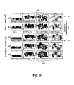
- Figure 9 includes views showing the toner layer formation states when the toner amount is small (when there is the gap) and when the toner particles are arranged in the single layer with no gap.
- (a) shows the case where the toner amount is remarkably small with respect to a flat surface, and the presence of many gaps cannot be avoided.
- (b) also in the case where the toner amount is somewhat increased compared with (a), when there are a three-dimensionally overlaid portion of the mutual toners and the gap-generated portion, the degree of covering of the paper base material is lowered and thus it is difficult to obtain good overlaying also during the secondary color formation.
- the spherical toner particles have a particle size distribution as shown in (d)
- the gap is liable to increase. That is, as shown in (c), in the case where the spherical toner particles with the same particle size are arranged in a closed-packed state, the toner particles can be arranged on the flat surface most efficiently.
- Figure 10 shows the toner layer formation states with respect to the toner amount (toner density) of the spherical toner particles with the same volume.
- the toner particles are in the state in which all the adjacent toner particles contact each other at the time of the closest-packed state and therefore the gap is smallest.
- the gap is gradually increased with a decreasing toner amount in the order of (b), (c) and (d).
- the yellow toners 603 as the upper layer for the second color are placed in the gaps formed by the cyan toners 601 as the lower layer irrespective of the toner amount.
- the upper layer toners increasingly enter the gaps of the lower layer toners.
- the upper layer toners are in a state in which they are placed on the lower layer toners and other hand, with a larger gap in the order of (b), (c) and (d), the upper layer toners are in a state in which they are caught in the gaps rather than the placed state. Further, with the larger gap, the upper layer toners are located at a lower position. That is, it is understood that the upper layer toners enter between the lower layer toners. Thus, it is well understood that the upper layer toners enter between the lower layer toners in a positional relation manner with the larger gap in the unfixed state.
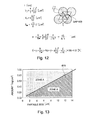
- Figure 12 shows the various parameters in the ideal arrangement state.
- the particle size (diameter) of the toner (particle) is L ( ⁇ m)
- a toner volume is Vo ( ⁇ m 3 )
- a planar toner particle projected area is So ( ⁇ m 2 )
- a unit area in which one toner particle is contained is S ⁇ ⁇ ⁇ m 2 and these parameters are represented as follows, respectively.
- V ⁇ 4 3 ⁇ ⁇ ⁇ L 2 3
- V ⁇ ⁇ ⁇ L 2 2
- S ⁇ 3 2 ⁇ L 2
- Figure 13 is a graph, from the above showing a relationship between the toner particle size and the toner amount per unit area (average height) in the ideal arrangement state.
- a solid line (-) represents the ideal arrangement state.
- a zone A shows a range in which the toner amount per unit area is larger than that in the ideal arrangement state
- a zone B shows a range in which the toner amount per unit area is smaller than that in the ideal arrangement state. That is, in the zone B, the toner amount with respect to the paper is insufficient and thus the gap occurs.
- the gap generated during the ideal arrangement i.e., a ratio T (%) of the gap when the toner particles are arranged in the closest-packed state (gap amount per unit area) ( Figure 12 ) is calculated as follows.
- the ratio H (%) is always 9.31 (%) in the toner particle size and the toner amount per unit area (average height) (solid line (-) in the graph) providing the ideal arrangement state shown in Figure 13 .
- the gap generated during the ideal arrangement state is 9.31 (%).
- Figure 14 includes views showing the closed-packed lamination state of the toners (toner particles) when the toner amount is increased.
- (a) shows a state in which the toners 611 for the first layer are arranged in the closed-packed state.
- a hexagon 612 is one unit area and by considering a state in which gaps A 613 and gaps B 614 in this hexagon are out of sight, it is possible to consider the toner amount per unit area when the paper is covered at 100 %.
- the gaps A 613 and the gaps B 614 are present and this ratio is 9.31 % per unit area.
- (b) and (c) show a state in which the toners 615 for the second layer are placed, so that it is understood that the toners 615 covers the gaps A 613.
- (d) and (e) show a state in which toners 616 for a third layer are placed. It is understood that the gaps B 614 is covered and thus the paper is covered at 100 %.
- Figure 15 shows the various parameters in a state in which the toner amount is below the toner amount in the ideal arrangement state.
- Figure 16 is a graph showing a relationship between the toner amount per unit area (average height) and the gap ratio when the toner particle size is 6 ( ⁇ m), as an example, from the above relation formula.
- a boundary line is dots showing the amount per unit area during the ideal arrangement state.
- the line shows a range in which the gap is generated and is a curve obtained on the basis of the above equation.
- the line is a curve obtained from the fact that the gap is 0 % (coverage: 100 %) when the three layers are laminated in the ideal state. From this curve, when the toner amount per unit area is below the ideal arrangement (boundary line), the gap is abruptly increased, i.e., the coverage is lowered. In a range in which the toner amount per unit area exceeds the boundary line, i.e., when the toner amount becomes large, when the toner amount per unit area exceeds the ideal arrangement state, it is understood that a change in amount of decrease in gap becomes small (improvement in coverage becomes dull).
- the state when the toner particle size is 6 ( ⁇ m) is described but needless to say, the change with the boundary line as a boundary is not limited thereto but is true for all of the particle sizes in the toner particles sizes within a normal use range.
- the present invention has be accomplished in view of such a phenomenon. Further, in the zone B in Figure 13 and in the range in which the toner amount is smaller than the boundary line rigid in Figure 16 , i.e., in the range in which the toner amount is less than the ideal arrangement state (closed-packed), even when there is the gap between the toners generated in principle, more proper color reproduction is realized. Specifically, the paper coverage in the single color and the color development of the secondary color by the satisfactory overlaying of different toners are improved.
- a density ⁇ (g/cm 3 ) is taken into consideration in the above formula representing the ideal arrangement state (the closest-packed state of the spherical toner particles) described above
- the toner amount per unit area can be converted into a toner amount per unit area A (mg/cm 2 ) represented by the following formula.
- "1/10" is a factor for unit alignment.
- the present invention has been accomplished in view of the above-described circumferences and its object is to provide an image forming apparatus which obtains a wide color reproduction region by making a degree of color overlaying so as not to decrease even in the case where a toner consumption (amount) is decreased.
- An object of the present invention is to provide an image forming apparatus capable of improving the degree of color overlaying of different color toners.
- the present invention provides an image forming apparatus, comprising:
- FIG. 1 (a) is a schematic illustration of the image forming apparatus in an embodiment, and (b) is a schematic cross-sectional view of a principal part of a fixing device.
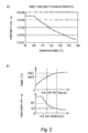
- (a) is a graph of a viscosity characteristic with respect to a temperature of a toner used in the embodiment
- (b) is a graph showing a relationship among a position in a fixing nip with respect to a conveyance direction, a toner temperature at its position and a melt viscosity of the toner at its toner temperature in the embodiment.
- Figure 3 includes schematic illustrations of binary image processing with respect to an obtained image in the embodiment.
- Figure 4 includes binary-processed images in the embodiment and in comparative embodiment.
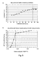
- (a) is a graph showing a relationship between a G region and chroma (saturation) in the embodiment
- (b) is a graph of a result of mathematical calculation of a relationship between a secondary color ratio and a toner amount per unit area in the embodiment.
- Figure 6 is a system block diagram for secondary color region ratio calculation.
- Figure 7 illustrates toner amounts and covering states of paper (recording material).
- Figure 8 illustrates toner amounts and toner layer formation states during a single layer and a secondary color.
- Figure 9 shows toner layer formation states when the toner amount is small (when there is a gap) and when toners are arranged in one layer with no gap.
- Figure 10 illustrates toner layer formation states, with respect to the toner amount, of spherical toners with the same volume.
- Figure 11 illustrates overlaying of the toners.
- Figure 12 is a view for illustrating various parameters during an ideal arrangement state.
- Figure 13 illustrates a relationship between a toner particle size and a toner amount per unit area.
- Figure 14 illustrates a closed-packed lamination state of toners.
- Figure 15 is a view for illustrating various parameters when a paper surface cannot be covered with toners.
- Figure 16 shows the toner amount per unit area and a gap ratio when a toner particle size is 6 ( ⁇ m).
- FIG. 1 Part (a) of Figure 1 is a schematic illustration of image forming apparatus 100 in this embodiment.
- This apparatus 100 is a four color-based full-color electrophotographic laser printer and is capable of forming, on a recording material S, a full-color image corresponding to electrical image information inputted from an external host device 102 connected to a control circuit portion (CPU) 101 in a communicatable manner and is capable of outputting the recording material S.
- the apparatus 102 is, e.g., a personal computer, an image reader, a facsimile machine or the like.
- the circuit portion 101 sends signals to and receives signals from the device 102, an operating portion 103 various image forming devices, thus managing an image forming sequence control.
- first to fourth four image forming portions Pa, Pb, Pc and Pd are juxtaposed.
- Each of the image forming portions is an electrophotographic process mechanism portion of a laser scanning exposure type, and the image forming portions include drum-type electrophotographic photosensitive members (hereinafter referred to as drums) 1 (1a, 1b, 1c, 1d), respectively, as an image bearing member.
- the image forming portions include, as process means acting on the drums 1, primary charges 2 (2a, 2b, 2c, 2d), developing devices 4 (4a, 4b, 4c, 4d), primary transfer chargers 5 (5a, 5b, 5c, 5d) and drum cleaners 6 (6a, 6b, 6c, 6d).
- the drum 1 is rotationally driven in the counterclockwise direction of an arrow at a predetermined speed (process speed).
- the primary charger 2 is a charging means for electrically charging the surface of the rotating drum 1 to a predetermined polarity and a predetermined potential uniform, and is a contact charging roller in this embodiment.
- the developing device 4 is a developing means for developing an electrostatic latent image, formed on the surface of the drum 1, as a chromatic color toner image, with a developer (chromatic color toner: color toner).
- Each of the developing devices 4 includes a sleeve for carrying the developer.
- the first forming portion Pa is an image forming portion for forming a toner image of yellow (Y color) on the drum 1a, and a Y color toner is accommodated in the developing device 4a.
- the second image forming portion Pb is an image forming portion for forming a toner image of magenta (M color) on the drum 1b, and an M color toner is accommodated in the developing device 4b.
- the third forming portion Pa is an image forming portion for forming a toner image of yellow (C color) on the drum 1c, and a C color toner is accommodated in the developing device 4c.
- the fourth image forming portion Ps is an image forming portion for forming a toner image of back (Bk color) on the drum 1d, and a Bk color toner is accommodated in the developing device 4d.
- the primary charger 5 is a transfer means for transferring the toner image formed on the drum 1 onto an intermediary transfer belt 11 described later, and a transfer roller (contact charging roller) is used in this embodiment.
- the drum cleaner 6 is a cleaning means for cleaning the drum surface by removing a residual deposited matter such as a residual toner or the like from the surface of the drum 1 after the primary transfer of the toner image onto the belt 11.
- a laser scanner unit 3 is provided at an upper portion of the image forming portions Pa, Pb, Pc and Pd.
- the unit 3 is an image exposure means for subjecting the primary-charged surfaces of the respective drums 1 to scanning exposure to laser lights L (La, Lb, Lc, Ld) modulated correspondingly to image information to form the electrostatic latent image.
- the unit 3 scans the drum surface with the laser light L emitted from a light source device by rotating the polygon mirror and deflects the beam (flux) of the scanning light by a reflection mirror and then focuses the beam on a generatrix line of the drum 1 by the f ⁇ lens, thus effecting light exposure.
- the electrostatic latent image depending on an image signal is formed.
- a voltage is applied to the sleeve provided to the developing device, so that the toner image is formed by a potential difference between a potential of the electrostatic latent image and a potential of the sleeve.
- an intermediary transfer belt unit 7 is provided.
- the unit 7 includes parallel three rollers consisting of a driving roller 8 in the first image forming portion Pa side, a turn roller 9 in the fourth image forming portion Pd side and a secondary transfer inner roller 10 located between the roller 8 and the roller 9 and below the both rollers 8 and 9. Further, the unit 7 includes an endless and flexible intermediary transfer belt 11 extended and stretched among the three rollers.
- the primary transfer roller 5 at each image forming portion P is provided inside the belt 11 and contacts the lower surface of the corresponding drum 1 via an upper-side belt portion between the rollers 8 and 9.
- a contact nip (portion) between the drum 1 and the belt 11 is a primary transfer portion.
- a secondary transfer outer roller 12 is contacted via the belt 11f.
- a contact nip between the belt 11 and the roller 12 is a secondary transfer portion.
- a belt cleaner 13 is disposed at a portion where the belt 11 is partly wound about the roller 8.
- the cleaner 13 is a cleaning means for cleaning the surface of the belt 11.
- a cleaning member 13a a web cleaning device using a cleaning web (nonwoven fabric) is used. A secondary transfer residual toner and another foreign matter on the belt 11 are wiped off by bringing the web 13a into contact to the surface of the belt 11.
- Full-color image formation on the recording material S is as follows. An image forming operation is started after image data and user setting information such as a size of the recording material used or a print number are transferred from the device 102 and the operating portion 103 to the circuit portion 101.
- the circuit 101 causes each image forming portion P to perform the image forming operation on the basis of a color separation image signal of the inputted color image information.
- the belt 11 is circulation-moved and driven in the clockwise direction of an arrow A at a predetermined speed.
- a sheet feeding mechanism portion (not shown) is driven with predetermined control timing, so that one sheet of the recording material S is separated and fed from a feeding cassette 14 in which the recording material S is stacked and accommodated and passes through a conveying path 15 to be conveyed to a registration roller pair 16.
- an unfixed toner image of each monochromatic (single) color is once fixed on the recording material and thereafter an unfixed toner image of another monochromatic color is fixed thereon. Then, such an operation that a fixing step is performed again is effected repeatedly, so that the image formation/fixing step for four colors are performed to obtain a full-color output image.
- the first color was Bk (color)
- the second color was C (color)
- the third color was M (color)
- the fourth color was Y (color). That is, from a side color to the surface of the recording material S ⁇ the Bk toner image, the C toner image, the M toner image and the Y toner image are successively formed by being image-formed and fixed, so that the Y toner image is image-formed/fixed at an outermost surface.
- the apparatus 100 of this embodiment applies, four times by changing the toner color to Bk, C, M and Y, to the same recording material S, the image formation/fixing step in which the unfixed toner image is formed with the chromatic color toner on the recording material S and its toner image is fixed on the recording material by being heated and pressed.
- the toner amount per unit area satisfying A ⁇ ( ⁇ L)/30 ⁇ 3 when the toner amount per unit area with respect to the recording material is A (mg/cm 2 ) when the unfixed toner image is formed on the recording material S is the maximum toner amount per unit area in formation of the unfixed toner image with each color toner.
- p is specific gravity (g/cm 3 ) of the toner and L is a weight-average particle size ( ⁇ m) of the toner.
- the toner having the specific gravity p of 1.1 (g/cm 3 ) and the weight-average particle size L of 6.0 ( ⁇ m) was used and was set so that the maximum toner amount per unit area of the unfixed toner on the recording material was 0.3 (mg/cm 2 ).
- a method of setting the maximum toner amount per unit area at 0.3 (mg/cm 2 ) a method of adjusting a potential difference between a potential on the drum and a potential of the sleeve may be cited.
- a maximum toner amount per unit area A1 for Y, a maximum toner amount per unit area A2 for Bk, a maximum toner amount per unit area A3 for Bk and a maximum toner amount per unit area A4 for Bk were all set at 0.3 (mg/cm 2 ).
- the present invention is not limited to this constitution but may also be a constitution in which the maximum toner amount per unit area satisfying A ⁇ ( ⁇ L)/30 ⁇ 3 is set for each color.
- this embodiment is characterized in that the above-described unfixed toner image is fixed so that a region in which the colors of the respective color toners are seen in an overlaid state is present at 84 % or more.
- the circuit portion 101 causes, of the first to fourth image forming portions Pa, Pb, Pc and Pd, only the fourth image forming portion Pd for forming the Bk toner image to perform the image forming operation.
- the drum 1 is only rotationally driven (blank rotation) and is not subjected to the image forming operation.
- the drum 1 and the belt 11 at each image forming portion are driven at the same peripheral speed.
- the circuit portion 101 executes processes of charging, exposure and developing at the fourth image forming portion Pd, so that the Bk toner image corresponding to a Bk color component image of the full-color image providing the maximum toner amount per unit area of 0.3 (mg/cm 2 ) of the unfixed toner on the recording material is formed on the surface of the drum 1d.
- the Bk toner image is successively primary-transferred from the drum 1d onto the surface of the belt 11 at the primary transfer portion.
- This transfer is effected by an electric field generated by applying, to the roller b5d, a primary transfer bias of an opposite polarity to a charge polarity of the toner and of a predetermined potential and (effected) by nip pressure at the primary transfer portion.
- the surface of the drum 1d after the transfer of the Bk toner image onto the belt 11 is cleaned by the cleaner 6d and is repetitively subjected to the image formation.
- the Bk toner image primary-transferred on the surface of the belt 11 is conveyed to the secondary transfer portion by subsequent movement of the belt 11.
- the recording material S fed from the cassette 14 is caught by a nip of the roller pair 16 in a rotation stop state at its leading end portion, thus being subjected to oblique movement correction to the stopped. Then, the roller pair 16 is driven with predetermined control timing, so that the recording material S is passed through the conveying path 17 by the roller pair 16 and is fed to the secondary transfer portion.
- the leading end portion of the recording material is introduced into the secondary transfer portion, so that the recording material S is nip-conveyed through the secondary transfer portion.
- the Bk toner image on the belt 11 is successively secondary-transferred onto the surface of the recording material S at the secondary transfer portion.
- This transfer is effected by an electric field generated by applying, to the roller 12, a secondary transfer bias of the opposite polarity to the toner charge polarity and of a predetermined potential and (effected) by nip pressure at the secondary transfer portion.
- the recording material S coming out of the secondary transfer portion is separated from the surface of the belt 11 and is passed through a conveying path 18 and then is introduced into a fixing device 19.
- the surface of the belt 11 after the separation of the recording material is cleaned by a cleaner 13 and is repetitively subjected to the image formation.
- the fixing device 19 is an image fixing means for fixing the unfixed toner image, as a fixed image, on the recording material S by heating and pressing the unfixed toner image, and in this embodiment, a heat-roller fixing device is used.
- Part (b) of Figure 1 is a schematic cross-sectional view of a principal part of the fixing device 19.
- the fixing device 19 forms a fixing nip N by vertically press-contacting parallel two rollers consisting of a fixing roller (fixing member) 20 and a pressing roller (pressing member) 21.
- the roller 20 is a roller of an outer diameter ⁇ of 60 mm prepared by forming a 2 mm-thick silicone rubber layer 20b on an outer peripheral surface of a core metal 20a of Fe having an inner diameter ⁇ of 54.6 mm, an outer diameter ⁇ of 56.0 mm and a thickness of 0.7 mm and further by coating a 30 ⁇ m-thick PFA tube 20c on its surface.
- the roller 21 is a roller similar to the roller 20. That is, the roller 21 is a roller of an outer diameter ⁇ of 60 mm prepared by forming a 2 mm-thick silicone rubber layer 21b on an outer peripheral surface of a core metal 21a of Fe having an inner diameter ⁇ of 54.6 mm, an outer diameter ⁇ of 56.0 mm and a thickness of 0.7 mm and further by coating a 30 ⁇ m-thick PFA tube 21c on its surface.
- the roller 20 and the roller 21 are vertically arranged in parallel and the both rollers are pressed under a total pressure of about 80 kgf (about 784 N) to form the fixing nip N with a predetermined width with respect to a recording material conveyance direction.
- the rollers 20 and 21 are rotationally driven in an arrow directions.
- a heater (heat source) H such as a halogen lamp is provided inside the core metal 20a of the roller 20.
- the heater H generates heat by being supplied with electric power from an electric power source portion (not shown). By this heat generation, the roller 20 is internally heated.
- a surface temperature of the roller 20 is detected by a temperature detecting element TH such as a thermistor and electrical information on a detected temperature is inputted into the circuit portion 101.
- the circuit portion 101 controls supplying electric power from the electric power source portion to the heater H so that detected temperature information inputted from the element is kept at electrical information corresponding to a predetermined fixing temperature.
- the circuit portion 101 effects temperature control so that the surface temperature of the roller 20 is kept at the predetermined fixing temperature.
- the rollers 20 and 21 are rotationally driven and in a state in which the roller 20 is raised in temperature to the predetermined fixing temperature and is temperature-controlled, the recording material S carrying the unfixed toner image t is introduced into the fixing nip N and is nip-conveyed through the nip N.
- the unfixed toner image t is fixed as a fixed image on the recording material surface by heating and pressure application at the nip N.
- a peripheral speed difference between the roller 20 and the roller 21 is substantially 0 %.
- a moving speed difference between a moving speed of the roller 20 and a moving speed of the recording material in the nip can be made substantially 0 %.
- the above-described condition is employed.
- the recording material S coming out of the nip N is separated from the surface of the roller 20 and is introduced from a conveying path 22 into a re-circulation conveying path (conveying path for fixing of plural times) 23.
- This introduction of the recording material S from the conveying path 22 to the recirculation conveying path 23 is effected by a flapper 24 switched into a first attitude.
- This recording material S is a recording material on which the fixed Bk toner image is formed and enters the conveying path 15 again from the conveying path 23, thus being conveyed to the registration roller pair 16. Then, the recording material S is subjected to the oblique movement correction by being caught at its leading end portion by the nip of the roller pair 16 in the rotation step state, thus being stopped. 2) Formation of C toner image for second color
- the circuit portion 101 executes, at the third image forming portion Pc, the procedures of the charging, the exposure and the development with respect to the drum 1c to form the C toner image, corresponding to a C color component image of the full-color image providing the maximum toner amount per unit area of 0.3 (mg/cm 2 ) of the unfixed toner on the recording material, on the surface of the drum 1c.
- the drum 1 is only rotationally driven and is not subjected to the image forming operation.
- the C toner image formed on the drum 1c is successively primary-transferred from the drum 1d onto the surface of the belt 11 at the primary transfer portion.
- the C toner image primary-transferred on the surface of the belt 11 is conveyed to the secondary transfer portion by subsequent movement of the belt 11.
- the roller pair 16 is driven with predetermined control timing, so that the recording material S on which the fixed Bk toner image has already been formed is passed through the conveying path 17 by the roller pair 16 and is fed to the secondary transfer portion.
- the C toner image on the belt 11 is successively secondary-transferred superposedly onto the Bk toner image-formed surface of the recording material S at the secondary transfer portion.
- the recording material S coming out of the secondary transfer portion is separated from the surface of the belt 11 and is passed through a conveying path 18 and then is introduced into a fixing device 19, so that the unfixed C toner image is fixed as a fixed image on the recording material surface by heating and pressure application in the nip N.
- the recording material S coming out of the nip N is separated from the surface of the roller 20 and is introduced from a conveying path 22 into a re-circulation conveying path 23. Then, the recording material S enters the conveying path 15 again and is subjected to the oblique movement correction by being caught at its leading end portion by the nip of the roller pair 16 in the rotation step state, thus being stopped. 3) Formation of M toner image for third color
- the circuit portion 101 executes, at the second image forming portion Pb, the procedures of the charging, the exposure and the development with respect to the drum 1b to form the M toner image, corresponding to a M color component image of the full-color image providing the maximum toner amount per unit area of 0.3 (mg/cm 2 ) of the unfixed toner on the recording material, on the surface of the drum 1b.
- the drum 1 is only rotationally driven and is not subjected to the image forming operation.
- the M toner image formed on the drum 1b is successively primary-transferred from the drum 1d onto the surface of the belt 11 at the primary transfer portion.
- the M toner image primary-transferred on the surface of the belt 11 is conveyed to the secondary transfer portion by subsequent movement of the belt 11.
- the roller pair 16 is driven with predetermined control timing, so that the recording material S on which the fixed Bk and C toner images have already been formed is passed through the conveying path 17 by the roller pair 16 and is fed to the secondary transfer portion.
- the C toner image on the belt 11 is successively secondary-transferred superposedly onto the already-fixed Bk and C toner images-formed surface of the recording material S at the secondary transfer portion.
- the recording material S coming out of the secondary transfer portion is separated from the surface of the belt 11 and is passed through a conveying path 18 and then is introduced into a fixing device 19, so that the unfixed M toner image is fixed as a fixed image on the recording material surface by heating and pressure application in the nip N.
- the recording material S coming out of the nip N is separated from the surface of the roller 20 and is introduced from a conveying path 22 into a re-circulation conveying path 23. Then, the recording material S enters the conveying path 15 again and is subjected to the oblique movement correction by being caught at its leading end portion by the nip of the roller pair 16 in the rotation step state, thus being stopped. 4) Formation of Y toner image for fourth color
- the circuit portion 101 executes, at the first image forming portion Pa, the procedures of the charging, the exposure and the development with respect to the drum 1a to form the Y toner image, corresponding to a Y color component image of the full-color image providing the maximum toner amount per unit area of 0.3 (mg/cm 2 ) of the unfixed toner on the recording material, on the surface of the drum 1a.
- the drum 1 is only rotationally driven and is not subjected to the image forming operation.
- the Y toner image formed on the drum 1a is successively primary-transferred from the drum 1d onto the surface of the belt 11 at the primary transfer portion.
- the Y toner image primary-transferred on the surface of the belt 11 is conveyed to the secondary transfer portion by subsequent movement of the belt 11.
- the roller pair 16 is driven with predetermined control timing, so that the recording material S on which the Bk toner image, the C toner image and the M toner image have already been formed and fixed is passed through the conveying path 17 by the roller pair 16 and is fed to the secondary transfer portion.
- the Y toner image on the belt 11 is successively secondary-transferred superposedly onto the already-fixed Bk, C and Y toner images-formed surface of the recording material S at the secondary transfer portion.
- the recording material S coming out of the secondary transfer portion is separated from the surface of the belt 11 and is passed through a conveying path 18 and then is introduced into a fixing device 19, so that the unfixed Y toner image is fixed as a fixed image on the recording material surface by heating and pressure application in the nip N.
- the recording material S coming out of the nip N is separated from the surface of the roller 20 and is introduced from a conveying path 22 into a conveying path 25 side, thus being discharged, as a four-color-based full-color image-formed product (output product) from a discharge opening 26 onto a discharge tray 27.
- the introduction of the recording material S from the conveying path 22 to the conveying path 25 is effected by the switching of the flapper 24 into a second attitude.
- the toners in this embodiment those using polyester-based resin were used.
- a toner manufacturing method a pulverization method or a method (polymerization method), for directly manufacturing the toners in a medium, such as suspension polymerization, interfacial polymerization, dispersion polymerization, or the like may be used.
- the toners manufactured by the pulverization method was used.
- the ingredients and the manufacturing method of the toners are not limited thereto.
- color toners of Y, M, C and Bk it is possible to use toners constituted by transparent thermoplastic resin materials which contain colants for the respective colors.
- color toners using, as a binder (resin), a polyester resin material having a temperature-melt viscosity property of the toner as shown in (a) of Figure 2 .
- the toners in this embodiment those of 1.1 (g/cm 3 ) in specific gravity p and 6.0 ( ⁇ m) in weight-average particle size L were used, and the maximum toner amount per unit area of the unfixed toner was set so as to be 0.3 (g/cm 2 ).
- a relationship among the specific gravity p of the toner, the weight-average particle size L and the toner amount per unit area A of the unfixed toner is not limited to the above setting if it satisfied: A ⁇ ⁇ L / 30 ⁇ ⁇ ⁇ 3.
- the melted state of the toner is determined by the fixing condition such as the fixing temperature, the fixing speed or the pressure and by a viscosity characteristic of the toner under the fixing condition, and a fixing pressure application state.
- the fixing condition such as the fixing temperature, the fixing speed or the pressure and by a viscosity characteristic of the toner under the fixing condition, and a fixing pressure application state.
- the fixing condition reaches a certain fixing condition, a degree of progression of toner melting is higher in the case where the lower toner viscosity is low, and therefore a fixing property is high or a color developing property is improved.
- the toner viscosity is high, the toner melting does not proceed and therefore the fixing property is low or the color developing property is degraded.
- the toner when the toner reaches a certain viscosity state, a degree of wetting and spreading of the toner over the recording material is larger in the case where the pressure of the fixing device is high and therefore the fixing property is high or the color developing property is improved. On the other hand, the degree of wetting and spreading of the toner over the recording material is smaller in the case where the pressure of the fixing device is low and therefore the fixing property is low or the color developing property is degraded.
- Part (b) of Figure 2 shows a relationship among a position in the fixing nip N with respect to the recording material conveyance direction a, the toner temperature at the position, and the melt viscosity of the toner at the toner temperature.
- the toner temperature was measured by applying a thermocouple (Type K Fine and Sheet thermocouple "KFST-10-100-200", mfd. by AMBE SMT Co.) onto the recording material (recording medium), and a distribution of pressure was measured by using a tactile sensor ("Sealer", mfd. by NITTA Corp.).
- the melt viscosity of the toner was measured by using an elevated flowtester ("CFT-100", mfd. by Shimadzu Corp.).
- CFT-100 mfd. by Shimadzu Corp.
- a sample, of 1.0 g in weight, molded by using a pressure molding device was extruded from a nozzle of 1 mm in diameter and 1 mm in length while applying a load of 20 kgf by a plunger at a temperature rise ratio of 5.0 °C/min, so that a lowering amount of the plunger of the flowtester was measured.
- the toner temperature is gradually increased from a fixing entrance side with respect to the recording material conveyance direction a and is highest at the nip exit.
- the toner viscosity is changed in the nip, and depending on whether the toner viscosity is high or low, the degree of progression of toner melting is changed and the wetting and spreading property with respect to the recording material when the toner is pressed by the fixing device is also changed.
- a region in which the colors of chromatic toners different in color are seen in an overlaid state will be described with respect to a detecting method and a detection result while including a comparative embodiment.
- the chromatic toners the Y (color) toner and the C (color) toner and used to conduct the verification, and a calculating method and a calculation result of a region in which the colors of Y toner image and the C toner image are overlaid, i.e., a region which the color appears green (G color) are shown as a representative example.
- G color a region which the color appears green
- the calculating method and the calculation result are not limited thereto.
- an image forming portion for forming the Y toner image on the recording material corresponds to the first image forming portion
- an image forming portion for forming the C toner image on the recording material corresponds to the second image forming portion.
- the process speed was 100 mm/s and the control temperature of the fixing portion was 180 °C.
- coated paper (basis weight: 150 g/m 2 ; paper glossiness: about 30 %) was used.
- the toner the toner of 1.1 (g/cm 3 ) in specific gravity p and 6.0 ( ⁇ m) in weight-average particle size was used, and the maximum amount per unit area of the unfixed toner on the recording material was set so as to be 0.3 (mg/cm 2 ).
- the obtained microscopic image was subjected to trimming at a central portion where the light quantity within an observation region was stable.
- the trimming was performed by using a software ("Adobe Photoshop", mfd. by Adobe Systems Inc.) and 2 mm square area was selected at an image central portion.
- this trimming operation is employed for being performed in the region in which the light quantity within the observation area. It is also possible to effect, in place of the trimming, calibration or the like of the light quantity balance within the observation region.
- the trimming image it is possible to perform binary-coded processing (binarization) at the secondary color portion and other portions.
- image processing software "Image-Pro Plus", available from Planetron Inc.
- a G (color) region in the observation region is calculated.
- the trimming image obtained from the microscopic image is subjected to binarization at the secondary color portion and at another portion (other than the secondary color portion) such as the single color portion or the background color portion, i.e., in the G region and in the C, Y or the background color region.
- the portion where the image appears G (color) is extracted in the obtained image by providing a threshold and is converted as a white portion and a portion where the image appears another color is converted as a black portion.
- a count of the number of the white portion regions and an area of each white portion area are stored as a count file.
- the area of the white portion of the obtained binarized image is integrated by, e.g., "Excel" (mfd. by Microsoft Corp.), so that an area ratio of the while portion was calculated as the G region.
- the binarized image of black portion/white portion as shown in (b) of Figure 3 is obtained.
- the ratio of the G area is calculated as follows.
- the chromatic toners the Y (color) toner and the C (color) toner and used to conduct the verification, and the calculation result of a region in which Y toner image and the C toner image are overlaid, i.e., a region which the color appears G color is shown as an example. However, this is also true for other colors and the calculation result is not limited thereto.
- the unfixed C toner image is formed on the drum 1c of the third image forming portion Pc and is primary-transferred onto the belt 11.
- the C toner image on the belt 11 is secondary-transferred onto the recording material S at the secondary transfer portion.
- the recording material S subjected to the transfer of the C toner image is introduced into the fixing device 19, so that the unfixed C toner image is fixed as a fixed image on the recording material surface y heat and pressure.
- the recording material S for which the image forming and fixing step for the first time is ended passes through the conveying paths 22, 23 and 15 and is introduced again into the secondary transfer portion.
- the unfixed Y toner image is formed on the drum 1a of the first image forming portion Pa and is primary-transferred onto the belt 11.
- the Y toner image on the belt 11 is secondary-transferred onto the recording material S, on which the already-fixed C toner image has been formed, at the secondary transfer portion.
- the recording material S subjected to the transfer of the Y toner image is introduced into the fixing device 19, so that the unfixed Y toner image is fixed as a fixed image on the recording material surface y heat and pressure.
- the recording material S for which the image forming and fixing step for the second time is ended and on which the already-fixed C toner image and Y toner image have been formed passes, as an output product, through the conveying paths 22 and 25 and the discharge opening 26 and is discharged on the tray 27.
- Comparative Embodiment 2 the case where only one time of the image formation is effected in the toner amount, set so that the maximum amount per unit area of the unfixed toner on the recording material is 0.6 (mg/cm 2 ), under the fixing condition in this embodiment is Comparative Embodiment 2, and the case where two times of the image formation are effected is Comparative Embodiment 3. Verification of these Comparative Embodiments 1, 2 and 3 was conducted. Incidentally, the unfixed toner amounts in Comparative Embodiments 2 and 3 were set to satisfy the condition: A > ( ⁇ L)/30 ⁇ 3.
- NOIF represents the number of (times of) image formation.
- *2) "UTA” represents the unfixed toner amount.
- RF represents the relational formula.
- GRR represents the G region ratio.
- values of index C* representing the chroma of the respective images were 96.8, 75.9, 85.4 and 87.2, respectively.
- the color coordinate is a value measured by Gretag Macbeth Spectro Scan ("Status Code A", mfd. by Gretag Macbeth AG).
- the G region ratio is less than 84 %.
- the G region ratio is a ratio lower than 48 % in Comparative Embodiment 1 after the fixing.
- the fixing step is performed in the maximum amount per unit area, of the unfixed toner on the recording material, of 0.6 (mg/cm 2 ).
- (c) is the image obtained by subjecting the obtained image to the binarization in case of Comparative Embodiment 2
- (d) is the image obtained by subjecting the obtained image to the binarization in the case of Comparative Embodiment 3 in which the two times of image formation were effected.
- the G region is no so increased.
- the chroma is not so increased. This is because the overlaying of the colors is large in the unfixed toner state and therefore sufficient overlaying of the colors is obtained in the one time of the image forming step.
- Part (a) of Figure 5 is verification of the chroma at the time when under the toner condition of this embodiment, the G region ratio is changed while changing the fixing condition.
- a slope with respect to the chroma is changed at 84 % as a boundary in terms of the G region ratio.
- the secondary color region of 84 % is a ratio at which the toners are adjacent to each other and the gap among the toners becomes minimum. Therefore, up to the secondary color region of 84 %, the chroma shows a tendency of abrupt increase or decrease and therefore it is important that the secondary color ratio is at least 84 % or larger.
- (b) of Figure 5 is, when the toners are 1.1 (g/cm 3 ) in specific gravity p and 6.0 ( ⁇ m) in weight-average particle size, a mathematically calculated relationship between the secondary color ratio and the toner amount per unit area when the toners are uniformly disposed on the recording material. As is understood from also (b) of Figure 5 , it is understood that a slope of the secondary color ratio is remarkably changed at 84 % as a boundary and a degree of increase becomes dull.
- the secondary color ratio is capable of exceeding 84 % by performing the image forming and fixing step for the 4 colors. Therefore, even in the case where the toner consumption is decreased, it is possible to prevent the degree of overlaying of the colors from being decreased and it is possible to provide an image forming apparatus which obtains a wide color reproduction region.
- the image forming apparatus in this embodiment forms the four color-based full-color image by applying, four times, the image forming and fixing step to the same recording material while changing the color of the toners
- the present invention is not limited thereto.
- the present invention is effectively applicable to an image forming apparatus for forming a superposed image of a plurality of chromatic toner images different in color by applying, at least two times, the image forming and fixing step to the same recording material while changing the control of the toners.
- the driving type of the fixing device was determined so that the moving speed of the fixing member contacted to the toner image on the recording material and the moving speed of the recording material are the substantially same speed at the fixing nip.
- the region in which the colors of the respective chromatic toners were seen in the overlaid state could be made 84 % or more.
- the present invention is not limited to a constitution in which the recording material is passed through the fixing nip plural times when the color image is formed on the recording material.
- a constitution in which the region where the colors of the chromatic toners are seen in the overlaid state is 84 % or more, during formation of the color image on the recording material, even when the number of times of passing of the recording material through the nip or in the case where the maximum toner amount per unit area satisfying: A ⁇ ( ⁇ L)/30 ⁇ 3 is set will be described.
- the driving type of the fixing device is determined so that a peripheral speed difference between the fixing member moving speed and the recording material moving speed in the fixing nip is 2 %.
- the fixing roller and the pressing roller are rotationally driven independently by driving motors, respectively. These rollers are independently rotated so that this rotational speed is 100 mm/s for the fixing roller and is 98 mm/s for the pressing roller to provide the peripheral speed difference of 2 % between the roller pair and thereby a force for spreading the toner, to be fixed, relatively in an in-plane direction is increased, so that it is possible to effectively increase the region in which the colors of the respective chromatic toners are seen in the overlaid state.
- NOIF represents the number of (times of) image formation.
- UTA represents the unfixed toner amount.
- RF represents the relational formula.
- GRR represents the G region ratio.
- the region in which the colors of the respective chromatic toners before the fixing are seen in the overlaid state is less than 84 % and by effecting the fixing by the fixing device of this embodiment, the G region ratio can exceed 84 %.
- the constitution in which the number of times of the image formation is one time is employed and on the other hand, the constitution in which the peripheral speed difference between the fixing member and the recording material in the fixing nip is provided by changing the driving type was employed.
- the region where the colors of the chromatic toners are seen in the overlaid state could be made 84 % or more, during formation of the color image on the recording material, even when the number of times of passing of the recording material through the nip or in the case where the maximum toner amount per unit area satisfying: A ⁇ ( ⁇ L)/30 ⁇ 3.
- the present invention is applicable.
- the present invention even in the case where the toner consumption is decreased, it is possible to obtain the wide color reproduction region by preventing the degree of overlaying of the colors from being decreased.
Landscapes
- Physics & Mathematics (AREA)
- General Physics & Mathematics (AREA)
- Engineering & Computer Science (AREA)
- Multimedia (AREA)
- Signal Processing (AREA)
- Color Electrophotography (AREA)
- Fixing For Electrophotography (AREA)
- Control Or Security For Electrophotography (AREA)
- Fax Reproducing Arrangements (AREA)
Applications Claiming Priority (2)
| Application Number | Priority Date | Filing Date | Title |
|---|---|---|---|
| JP2010193703A JP5641829B2 (ja) | 2010-08-31 | 2010-08-31 | 画像形成装置 |
| PCT/JP2011/070305 WO2012029980A1 (fr) | 2010-08-31 | 2011-08-31 | Dispositif de formation d'images |
Publications (2)
| Publication Number | Publication Date |
|---|---|
| EP2613202A1 true EP2613202A1 (fr) | 2013-07-10 |
| EP2613202A4 EP2613202A4 (fr) | 2015-03-25 |
Family
ID=45773049
Family Applications (1)
| Application Number | Title | Priority Date | Filing Date |
|---|---|---|---|
| EP11821991.4A Withdrawn EP2613202A4 (fr) | 2010-08-31 | 2011-08-31 | Dispositif de formation d'images |
Country Status (6)
| Country | Link |
|---|---|
| US (1) | US8705996B2 (fr) |
| EP (1) | EP2613202A4 (fr) |
| JP (1) | JP5641829B2 (fr) |
| KR (1) | KR101430375B1 (fr) |
| CN (1) | CN103140809B (fr) |
| WO (1) | WO2012029980A1 (fr) |
Families Citing this family (7)
| Publication number | Priority date | Publication date | Assignee | Title |
|---|---|---|---|---|
| JP5517876B2 (ja) * | 2010-10-14 | 2014-06-11 | キヤノン株式会社 | 定着装置 |
| JP2013044838A (ja) | 2011-08-23 | 2013-03-04 | Canon Inc | 画像形成装置 |
| JP5904817B2 (ja) * | 2012-02-17 | 2016-04-20 | キヤノン株式会社 | 画像形成装置 |
| JP5972059B2 (ja) * | 2012-06-15 | 2016-08-17 | キヤノン株式会社 | 画像形成装置 |
| JP2014134678A (ja) * | 2013-01-10 | 2014-07-24 | Canon Inc | 画像形成装置 |
| JP6012480B2 (ja) * | 2013-01-10 | 2016-10-25 | キヤノン株式会社 | 画像形成装置 |
| JP6335651B2 (ja) | 2014-05-26 | 2018-05-30 | キヤノン株式会社 | ヒータ、及びこれを備えた画像加熱装置 |
Family Cites Families (13)
| Publication number | Priority date | Publication date | Assignee | Title |
|---|---|---|---|---|
| JPS6491156A (en) * | 1987-10-02 | 1989-04-10 | Ricoh Kk | Fullcolor electrophotographic method |
| JPH0274976A (ja) * | 1988-09-12 | 1990-03-14 | Fuji Xerox Co Ltd | 定着装置における差動駆動装置 |
| JP3145932B2 (ja) * | 1996-09-09 | 2001-03-12 | 新潟日本電気株式会社 | カラー画像形成装置およびカラー画像形成方法 |
| JP2004029563A (ja) | 2002-06-27 | 2004-01-29 | Sharp Corp | 定着装置および画像形成装置 |
| JP2005195670A (ja) | 2003-12-26 | 2005-07-21 | Fuji Xerox Co Ltd | 画像形成方法 |
| JP4277682B2 (ja) | 2003-12-26 | 2009-06-10 | 富士ゼロックス株式会社 | 画像形成方法 |
| JP2004295144A (ja) | 2004-06-04 | 2004-10-21 | Ricoh Co Ltd | 画像形成装置 |
| JP2006349701A (ja) * | 2005-06-13 | 2006-12-28 | Konica Minolta Business Technologies Inc | 画像形成装置、および、画像形成方法 |
| JP4994768B2 (ja) | 2005-12-09 | 2012-08-08 | キヤノン株式会社 | 画像形成装置 |
| JP5089371B2 (ja) * | 2007-12-25 | 2012-12-05 | キヤノン株式会社 | 画像形成装置 |
| JP5339130B2 (ja) * | 2009-01-19 | 2013-11-13 | 富士ゼロックス株式会社 | 画像形成装置 |
| WO2011030925A1 (fr) * | 2009-09-10 | 2011-03-17 | キヤノン株式会社 | Dispositif de formation d'image |
| JP5517876B2 (ja) * | 2010-10-14 | 2014-06-11 | キヤノン株式会社 | 定着装置 |
-
2010
- 2010-08-31 JP JP2010193703A patent/JP5641829B2/ja not_active Expired - Fee Related
-
2011
- 2011-08-31 WO PCT/JP2011/070305 patent/WO2012029980A1/fr not_active Ceased
- 2011-08-31 KR KR1020137007270A patent/KR101430375B1/ko not_active Expired - Fee Related
- 2011-08-31 EP EP11821991.4A patent/EP2613202A4/fr not_active Withdrawn
- 2011-08-31 CN CN201180046704.7A patent/CN103140809B/zh not_active Expired - Fee Related
-
2013
- 2013-02-27 US US13/779,151 patent/US8705996B2/en not_active Expired - Fee Related
Also Published As
| Publication number | Publication date |
|---|---|
| US8705996B2 (en) | 2014-04-22 |
| WO2012029980A1 (fr) | 2012-03-08 |
| CN103140809B (zh) | 2015-07-15 |
| US20130170849A1 (en) | 2013-07-04 |
| JP2012053139A (ja) | 2012-03-15 |
| JP5641829B2 (ja) | 2014-12-17 |
| EP2613202A4 (fr) | 2015-03-25 |
| CN103140809A (zh) | 2013-06-05 |
| KR20130079509A (ko) | 2013-07-10 |
| KR101430375B1 (ko) | 2014-08-13 |
Similar Documents
| Publication | Publication Date | Title |
|---|---|---|
| US8705996B2 (en) | Image forming apparatus controlling toner image overlapping ratio | |
| US8649696B2 (en) | Image forming apparatus including an image area glossiness control feature | |
| KR100979361B1 (ko) | 화상 형성 장치 | |
| CN101566812B (zh) | 控制装置及控制方法 | |
| US8655228B2 (en) | Image forming apparatus | |
| US20110206401A1 (en) | Image forming apparatus | |
| US8995865B2 (en) | Image forming apparatus | |
| US8543047B2 (en) | Image forming system | |
| JP2006251722A (ja) | 画像形成装置 | |
| US9008529B2 (en) | Image forming apparatus, image forming system, non-transitory computer readable medium, and image forming method | |
| JP2015018120A (ja) | 画像形成装置 | |
| EP2743774A1 (fr) | Unité de formation d'images | |
| US7813684B2 (en) | Transferring and fixing apparatus and image forming apparatus including the same | |
| US9128405B2 (en) | Image forming apparatus controlling charging voltage based on image density information | |
| JP5904817B2 (ja) | 画像形成装置 | |
| JP3548406B2 (ja) | 画像形成装置 | |
| JP2005265917A (ja) | 光沢付与装置およびこれを用いた画像形成装置 | |
| US7701615B2 (en) | Image forming method and image forming apparatus | |
| US20120269561A1 (en) | Image forming apparatus | |
| JP2021148926A (ja) | 画像形成装置 | |
| JP2007199287A (ja) | 画像形成装置 | |
| JP2008122796A (ja) | 画像形成装置 | |
| JP2016161582A (ja) | 画像形成装置 |
Legal Events
| Date | Code | Title | Description |
|---|---|---|---|
| PUAI | Public reference made under article 153(3) epc to a published international application that has entered the european phase |
Free format text: ORIGINAL CODE: 0009012 |
|
| 17P | Request for examination filed |
Effective date: 20130402 |
|
| AK | Designated contracting states |
Kind code of ref document: A1 Designated state(s): AL AT BE BG CH CY CZ DE DK EE ES FI FR GB GR HR HU IE IS IT LI LT LU LV MC MK MT NL NO PL PT RO RS SE SI SK SM TR |
|
| DAX | Request for extension of the european patent (deleted) | ||
| A4 | Supplementary search report drawn up and despatched |
Effective date: 20150219 |
|
| RIC1 | Information provided on ipc code assigned before grant |
Ipc: G03G 15/20 20060101ALI20150213BHEP Ipc: G03G 15/00 20060101ALI20150213BHEP Ipc: H04N 1/23 20060101ALI20150213BHEP Ipc: G03G 15/01 20060101AFI20150213BHEP |
|
| STAA | Information on the status of an ep patent application or granted ep patent |
Free format text: STATUS: THE APPLICATION HAS BEEN WITHDRAWN |
|
| 18W | Application withdrawn |
Effective date: 20170331 |